Note: Descriptions are shown in the official language in which they were submitted.
CA 02693341 2010-01-18
WO 2009/045955
PCT/US2008/078120
TOOL WITH REPLACEABLE BLADE
BACKGROUND OF THE INVENTION
The present invention generally relates to hand tools,
and more particularly to a wallboard joint taping knife with a
replaceable blade.
Taping knives or tools, which have varying blade widths,
are used to finish wallboard construction projects and create a smooth
transition between abutting wallboard surfaces. After wallboard panels
are in place, a smaller (e.g. 4 inch - 6 inch) taping knife is generally
used to apply a settable joint compound and drywall tape to the joints
formed by the abutting wallboard surfaces. At this stage, unseated
nails must also be finally set into the wallboards and supporting studs.
After the joint compound dries, progressively larger (e.g. 8 inch - 14
inch) knives are used to apply more compound to the joint areas. This
step is repeated, with intermittent sanding steps, until the joint is
sufficiently flat and smooth.
Presently, performing a wallboard joint finishing job
generally requires the use of several taping knives as described
above. Wallboard finishing practitioners typically need to purchase,
carry and maintain a wide variety of taping knives of varying blade
widths. Also, conventional taping knives used by professionals
frequently need replacement due to worn or corroded blades.
1
CA 02693341 2010-01-18
WO 2009/045955
PCT/US2008/078120
BRIEF SUMMARY OF THE INVENTION
The present taping knife features a replaceable blade.
The handle has a blade chamber into which a blade having a working
portion, a blade sleeve and a tang opposite the working portion is
inserted in a releasably locking engagement. A positive engagement
between the handle and the blade helps to restrict movement of the
blade with respect to the handle. The blade sleeve helps to create this
positive engagement. At least two locking elements provide the
releasable locking engagement and also help to provide the positive
connection between the handle and the blade.
To More specifically, a tool is provided, having a handle with
a blade chamber defining a blade chamber cavity, a first locking
element, and a second locking element that is user actuated, and a
removable blade with a tang engageable in the blade chamber cavity
and a working portion. A blade sleeve, is also provided, at least a
portion of which is located on the tang.
In another embodiment, a handle for a tool having the
handle and a blade, includes a blade chamber defining a blade
chamber cavity, a first locking element provided with a biasing
element, and a second locking element that is user actuated.
In another embodiment, a blade is provided for a tool
with a handle having a blade chamber defining a blade chamber
cavity, a first locking element and a second locking element that is
user actuated. The blade includes a tang, a working portion, a first
locking element receiving portion, a second locking element receiving
portion, and a blade sleeve comprising handle mating portions.
2
. CA 02693341 2016-04-01
In yet another embodiment, a blade sleeve is provided for
a tool having a handle with a blade chamber defining a blade chamber
cavity and a blade with a tang and a working portion. The blade sleeve
includes handle mating portions and a blade mating portion. The blade
sleeve is constructed and arranged to provide a positive connection
when the blade is inserted into the blade chamber cavity of the handle.
In a broad aspect, moreover, the present invention
provides a tool comprising: a handle comprising a blade chamber
defining a blade chamber cavity and a recessed portion, a first locking
element enclosed within said handle, and a second locking element
that is user actuated and located in said recessed portion, said
second locking element being accessible by the user; a removable
blade comprising a tang engageable in said blade chamber cavity and
a working portion; a blade sleeve, at least a portion of which is located
on said tang; and a cover movably connected to said handle and
configured to cover said recessed portion.
BRIEF DESCRIPTION OF THE SEVERAL
VIEWS OF THE DRAWINGS
FIG. 1 is a top perspective view of an embodiment of the
present taping knife;
FIG. 2 is a top perspective, partially exploded view of the
taping knife of FIG. 1 in which the blade is shown in a removed position
with respect to the handle;
FIG. 3 is an end perspective view of the taping knife of
FIG. 2;
FIG. 4 is a front view of an embodiment of the handle of
the present taping knife;
3
CA 02693341 2016-04-01
FIG. 5 is a bottom view of an embodiment of the present
handle showing an indicium corresponding to an interchangeable blade
type;
FIG. 6 is an exploded perspective view of the taping knife
of FIG. 1;
FIG. 7 is a cross section of the taping knife taken along
line 7-7 of FIG. 1 and in the direction generally indicated;
FIG. 8 is a top fragmentary perspective view of an
embodiment of the present handle; and
3a
CA 02693341 2010-01-18
WO 2009/045955
PCT/US2008/078120
FIG. 9 is a bottom view of an embodiment of the present
tool having a rectangular shaped blade and a corresponding indicium.
DETAILED DESCRIPTION OF THE INVENTION
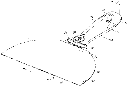
Referring to FIGs. 1 and 2, a taping knife generally
designated 10 is preferably made with a flat blade 12 and a handle 14.
The blade 12 has a working portion 16, a working edge 18, a tang 20
opposite the working portion 16, and a blade sleeve 22 at least
partially covering the tang 20. While other materials are contemplated,
the working portion 16 of the blade 12 is preferably made primarily out
of stainless steel and the blade sleeve 22 of a plastic material, such as
polypropylene. The handle 14 of the tool 10 preferably has a blade
chamber 24 that defines a blade chamber cavity 26 into which the
blade 12 is inserted, locking elements 28, 30 that help to retain the
blade in the handle, a hammer element 32, and a resilient overlay 34
that provides for a strong yet comfortable grip.
As is fairly common in the art, the handle 14 is preferably
made of a pair of opposing housing halves 15 which encompass the
blade chamber 24 and are made of a rigid material such as molded
plastic or the like. It is preferred that the blade chamber 24 is retained
in the handle 14 by one or more blade chamber retaining elements 38,
such as rivets. Preferably, the retaining elements 38 pass through
blade chamber retaining element receiving portions 40 that are defined
by the blade chamber 24 and located in several areas of the blade
chamber. It is contemplated that certain of the rivets 38 are covered
by rivet covers 42 engaged in external recesses of the handle halves
15 so that the handle 14 has a generally smooth surface.
4
CA 02693341 2010-01-18
WO 2009/045955
PCT/US2008/078120
A feature of the present tool 10 is that the blade 12 is
releasably secured in the handle 14 by at least two mechanisms,
preferably using distinct fastening or clamping technologies. The first
releasable locking element 28 of the handle 14 is preferably a biasing
element such as a spring ball. The first locking element 28 preferably
provides an automatic, audible and/or tactile indicator of a positive
connection between the tang 20 of the blade 12 and the blade
chamber 24 of the handle 14 upon insertion. In embodiments in which
a spring ball 28 is the biasing element, the tang 20 of the blade 12
preferably defines a hole that serves as a first locking element
receiving portion 44.
When the blade 12 is inserted into the blade chamber
24, the edge of the tang 20 displaces the spring ball 28 into a
compressed position. In a preferred embodiment, the edge of the tang
20 opposite the working portion 16 is tapered to more easily displace
the spring ball. When the blade 12 is fully inserted, the spring ball 28
moves into a de-compressed position as it enters into the first locking
element receiving portion 44 of the tang 20, and the blade 12 is
thereby retained in the handle 14.
In certain embodiments, the blade chamber 24 has a first
locking element guiding portion 46 that helps to keep the first locking
element 28 in the correct location within the handle 14. For instance,
in FIG. 6 the guiding portion 46 has a tubular, sleeve-like configuration
for providing a space in which the spring ball 28 resides.
Preferably, the second locking element 30 of the tool 10
is user actuated and is in the form of a lock screw. The use of a lock
screw 30 helps to provide a tight friction fit which decreases movement
of the blade 12 with respect to the handle 14, especially in a plane
perpendicular to the blade. In embodiments in which the tang 20 has
5
CA 02693341 2010-01-18
WO 2009/045955
PCT/US2008/078120
a tapered edge, the edge can be used as a screwdriver to remove the
lock screw 30. Besides having a head 47 that can receive
conventional screw drivers, in a preferred embodiment, the lock screw
30 has a swiveling D-ring 48 which moves between a retracted or
storage position, and a raised or operative position so that the D-ring
is positionable to be parallel and in line with a shank of the lock screw.
When the D-ring 48 is in this position, it is simpler for a user to screw
and unscrew the locking element 30 without the use of a screwdriver
or other tools.
Referring to FIGs 6 and 8, an optional conical spring 50
is attached to the lock screw 30 to aid in retaining the lock screw on
the handle 14 when it is in the unlocked position. Preferably, the
conical spring 50 rests in a lock screw washer 52 when the lock screw
30 is in a locked position. It is noted that the conical spring 50 has
added benefits of taking up less volume in the lock screw washer 52
when in the locked position, as well as assisting to force the lock
screw 30 away from the lock screw washer 52 when the lock screw is
being unscrewed. Moreover, the lock screw washer 52 provides for a
large surface area that transfers compressive force more broadly
across the handle 14 than a lock screw 30 alone, which in turn results
in a greater surface area of the handle contacting the blade12. This
helps to provide a better positive connection between the handle 14
and the blade 12. The second locking element 30 in a preferred
embodiment is retained in the handle by a second locking element
retaining element 54. In the case of a lock screw 30, the second
locking element retaining element 54 is a lock screw nut located
between one of the housing halves 15 and an opposite side of the
blade chamber 24 from the lock screw washer 52.
6
CA 02693341 2010-01-18
WO 2009/045955
PCT/US2008/078120
In a preferred embodiment, the lock screw washer 52
rests in a washer seat 51 within the handle 14 as shown in FIG 8.
When the lock screw 30 is in a locked position, the washer seat 51 is
compressed against the blade chamber 24 and acts like a vise to
retain the blade 12 in the chamber 24. The washer seat 51 has a
slight flex to it or is otherwise biased so that when the lock screw 30 is
in an unlocked position, the washer seat does not rest against the
blade chamber 24. This helps decrease the amount of pressure
exerted on the blade 12 so that it can be easily released from the
handle 14.
Preferably, the second locking element 30 passes
through a second locking element receiving portion 53 that is defined
by the tang 20. In a preferred embodiment, the blade sleeve 22 also
defines a second locking element receiving portion 55, which is in
registry with the corresponding formation 53 on the tang 20, and the
second locking element 30 passes through both the second locking
element receiving portion 53 of the tang 20 and the second locking
element receiving portion 55 of the blade sleeve 22 as shown in FIGs
2 and 6.
Preferably, in the retracted position, the D-ring 48 of the
lock screw 30 is flush with a surface of the handle 12 when the lock
screw is in a locked position, and it is covered with a resilient cover 56
that results in a smoother and more uniform surface. It is
contemplated that the cover 56 is removable and is rotatable to the
side to allow access to the lock screw 30 in certain embodiments.
This cover 56 for the user actuated locking element 30 is preferably
attached to the handle 14 with a tether 58 (FIG. 6) so that it is not lost
when it is removed to access the locking element.
7
CA 02693341 2010-01-18
WO 2009/045955
PCT/US2008/078120
In some embodiments, the hammer element 32 is
located on a side opposite the blade 12, and the hammer element is
attached to a hammer element receiving portion 60 of the handle 14
using a hammer element retaining element 62 such as a retaining pin.
It is contemplated that the hammer element 32 is made out of the
same material of the handle14, but it is preferable that the hammer is
made from a harder material relative to the handle. For instance, in
one embodiment the handle 14 is made primarily out of polypropylene,
and the hammer element 32 is made primarily out of zinc.
While in the preferred embodiment the first locking
element is the spring ball 28 and the second locking element is the
locking screw 30, it will be appreciated that the identity of the first and
second locking elements can be reversed or that both the first and
second locking elements can be either the lock screw or the spring
ball.
In certain embodiments, the blade chamber 24 is
disposed in a blade chamber housing 64 formed by the handle halves
15 that are made primarily out of polypropylene and provides the
overall shape to the handle 14. Preferably, first and second
identification inserts 66, 68 are attached to the blade chamber housing
64 as show in FIG. 6. Such inserts 66, 68 are constructed and
arranged to provide for a relatively smooth transition from the insert to
the blade chamber housing 64. In an embodiment, the handle 14 also
has an eyelet 70 on the end opposite the blade 12 so that a user can
hang the tool 10 on a hook when not in use. It is contemplated that at
least some portion of the handle 14 and preferably the blade chamber
housing 64 and the inserts 66, 68 are covered with the resilient overlay
34 which provides the user with a comfortable yet strong grip,
8
CA 02693341 2010-01-18
WO 2009/045955
PCT/US2008/078120
especially when the tool 10 is used with a viscous fluid such as joint
compound.
The blade sleeve 22 helps provide the positive
connection between the blade 12 and the handle 14. Preferably, the
blade sleeve 22 and blade chamber 24 are constructed and arranged
to provide for a jam fit when the blade sleeve is inserted into the blade
chamber. This jam fit is beneficial because it will result in less motion
of the blade 12 with respect to the handle 14. One configuration of the
blade sleeve 22 that is contemplated is a sleeve that has a tang
covering portion 69 that is wedge shaped with respect to a plane of the
blade 12. This configuration helps provide a jam fit and helps prevent
lateral motion of the blade 12 with respect to the handle 14.
An optional feature of the configuration of the sleeve 22
is that it is wedge shaped with respect to a plane perpendicular to the
plane of the blade. This configuration helps provide a jam fit and helps
restrict motion of the blade 12 with respect to the plane perpendicular
to the plane of the blade. Yet another optional configuration for the
sleeve 22 is a wedge shape both in a plane of the blade 12 and in a
plane perpendicular to the plane of the blade. This configuration helps
further in achieving a jam fit and helps to prevent relative motion of the
blade 12 laterally and with respect to a plane perpendicular to that of
the blade.
In a preferred embodiment, the blade sleeve 22 has
blade mating portions 71 that matingly engage with the blade 12, as
well as handle mating portions 72 that mate with the handle 14. It is
contemplated that the mating of the blade sleeve 22 with the blade
chamber 24 of the handle 14 is accomplished by constructing and
arranging the handle mating portions 72 of the blade sleeve in a
concave configuration with respect to corresponding convex blade
9
CA 02693341 2010-01-18
WO 2009/045955
PCT/US2008/078120
sleeve mating portions 74 of the blade chamber 24. The handle
mating portions 72 are preferably located lateral to the tang 20.
Mating engagement helps decrease the amount of motion or free-play
of the blade 12 with respect to the handle 14. Other configurations in
addition to concave/convex configurations are also contemplated and
are to be considered within the scope of this disclosure.
In certain embodiments, a portion of the blade sleeve 22
covers the tang portion 20 of the blade 12, and a portion of the blade
sleeve covers some of the working portion 16 of the blade. When the
blade 12 with the blade sleeve 22 is inserted into the blade chamber
24, a positive connection is obtained. That is, the blade sleeve 22
provides for a tight friction fit or jam fit that prevents relative motion of
the blade 12 with respect to the handle 14. In certain preferred
embodiments, at least a portion of the blade sleeve 22 is made out of
a resilient material that provides for a water tight seal between the
blade 12 and the handle 14 so joint compound or other materials do
not inadvertently enter into the blade chamber cavity 26.
The blade sleeve 22 is preferably fastened to the blade
12, but in certain embodiments it is removably placed on the blade.
One method of permanently fastening the blade sleeve to the blade is
by use of a rivet 76 as shown in FIG. 6, but other fastening techniques
such as the use of chemical adhesives, for example, are also
contemplated.
In one preferred embodiment, the blade sleeve 22 is
made from a polypropylene material, slid onto the blade 12 from the
tang portion 20 and riveted thereto. However, in certain embodiments
the blade sleeve 22 is integral to the blade. This is accomplished, for
example, if the blade 12 and the blade sleeve 22 are cast as one piece
in embodiments in which the blade and the blade sleeve are made out
CA 02693341 2010-01-18
WO 2009/045955
PCT/US2008/078120
of the same material. In other embodiments, the blade 12 is made out
of one type of metal, and the blade sleeve 22 is made out of a different
type of metal or plastic and is cast, molded or welded onto the blade.
Different sizes and shapes of blades are contemplated in
the present taping knife 10. For instance, certain embodiments of the
blade 12 have a generally curved shape opposite the working edge 18
of the blade as shown in FIG. 1. Referring to FIG. 9, an alternate
embodiment of the knife 10 is generally designated 100. Components
shared with the knife 10 are designated with identical reference
numbers. Distinctive features of the knife 100 include a generally
rectangular shape of the blade 120 and a handle 140 constructed and
arranged to receive the blade. Preferably, the blades 12, 120 are
interchangeably inserted into the handle 14, 140 and are provided in at
least a small size (having a working edge that is six inches long, for
instance) and a large size (having a working edge that is ten inches
long for instance). In fact, it is contemplated that different blade sizes
are used interchangeably with a single handle 14, 140 so that a user
may use a small blade 12 when applying the first coats of joint
compound to a wall and then switch to a larger blade when applying a
final coat of joint compound. It is also contemplated that a particular
handle 14, 140 is configured to receive only one type of blade 12, 120
that has varying sizes, while in other embodiments the handle is
configured to receive multiple blade types.
However, in a preferred embodiment a particularly
shaped blade 12 is only useable with a handle 14 of a particular type.
In such embodiments, the blade sleeve mating portions 7401 the
handle 14 are engageable to a blade 12 with a blade sleeve 22 with
corresponding blade chamber mating portions 72 that are not able to
engage with blade sleeve mating portions of different handle types.
11
CA 02693341 2010-01-18
WO 2009/045955
PCT/US2008/078120
For instance, a manufacturer decides to provide handles 12 of a
particular type "R." Type "R" handle's blade chamber 24 is
constructed and arranged to have curved convex blade sleeve mating
portions 74 such as shown in FIGs. 3 and 4. The manufacturer
provides all of its blades 12 of varying sizes that are rounded opposite
the working edge (as shown in FIG. 1) with blade sleeves 22 that are
constructed and arranged to have curved concave blade chamber
mating portions 72 that perfectly mate with the curved convex blade
sleeve mating portions 74 of the blade chamber 24 when these
rounded blades are inserted into the handle 14 of type "R."
Furthermore, in this scenario the manufacturer provides
a handle 14 of a particular type "S." The type "S" handle's blade
chamber 24 is constructed and arranged to have generally squared
convex blade sleeve mating portions (not shown). The manufacturer
provides all of its blades 120 of varying sizes that are rectangular in
shape (as shown in FIG. 9) with blade sleeves 220 that are
constructed and arranged to have squared concave blade chamber
mating portions (not shown) that perfectly mate with the squared
convex blade sleeve mating portions (not shown) of the blade
chamber when these rectangular blades 120 are inserted into the
handle of type "S."
The rectangular blades 120 would not fit into a type "R"
handle 14, and the rounded blades 12 would not fit into a type "S"
handle 140. To aid users in identifying which type of blade is used
with a particular type of handle, it is contemplated that the
manufacturer will imprint or otherwise place an indicium 78, 780 on
each handle type that corresponds with an interchangeable blade
type. For example, in preferred embodiments handles 14 that can
receive rounded blades are imprinted with an indicium 78 that looks
12
CA 02693341 2010-01-18
WO 2009/045955
PCT/US2008/078120
like a handle with a rounded blade as is shown in FIG. 5. Handles 140
that can receive rectangular blades 120 are imprinted with an indicium
780 that looks like a handle with a rectangular blade as shown in FIG.
9.
While a particular embodiment of the present taping knife
with replaceable blade has been shown and described, it will be
appreciated by those skilled in the art that changes and modifications
may be made thereto without departing from the invention in its
broader aspects and as set forth in the following claims.
13