Note: Descriptions are shown in the official language in which they were submitted.
CA 02693360 2009-12-18
WO 2009/063331 PCT/IB2008/003859
ADJUSTABLE CLOSURE FOR A CONTAINER
FIELD OF THE INVENTION
[0001] The invention is generally directed to a closure for a container. More
specifically, the invention is directed to a closure system that is
kinematically linked
to a container so that the closure is moveable from a closed position to an
open
position.
BACKGROUND
[0002] Containers are often covered by some sort of closure or lid to prevent
spillage
of the contents therein. For example, beverage containers are typically fitted
with
lids to protect against splashing during transport of the beverage, as well as
to
mitigate spillage when the container is tipped. A conventiorial lid is usually
screwed
onto corresponding threads surrounding a container opening. While these lids
are
effective against spillage when a container is tipped, these lids also prevent
immediate
access to contents therein. In other words, a user must first unscrew the lid
before
being able to drink the beverage. Not only is having to unscrew a lid before
each sip
time consuming, it can also be dangerous for a user who is trying to enjoy a
beverage
while driving.
[0003] Consequently, lids that allow immediate access to a beverage while
protecting
against splash and spillage have become increasing popular. Such a lid is
typically
sized slightly larger than a container opening so that the lid seals the
opening via a
friction fit. The lid also includes a first opening for the beverage to flow
through, as
well a second, smaller vent opening to allow air to enter a container to
prevent a
vacuum from forming therein by replacing the space previously occupied by a
beverage after the beverage flows out of the container.
[0004] While these lids do allow a user to easily access a beverage within a
container,
these lids suffer from significant drawbacks. For example, since each of these
lids
includes two openings, a container is never completely sealed. As a result, a
beverage
will spill out of the container if the container is tipped or jarred. Further,
in light of
the friction fit, this type of lid often does not provide a proper seal for
the opening of
1
CA 02693360 2009-12-18
WO 2009/063331 PCT/IB2008/003859
a container, and consequently, the beverage leaks from the container when the
container is tilted. Accordingly, there is a need for a lid or closure system
that
protects against spillage and splashing by forming a complete seal, as well as
provides
convenient access to the contents of a container.
SUMMARY
[0005] The present invention is directed to a closure that is kinematically
linked to a
container so as to provide a complete seal of the container opening and to
allow easy
access to contents therein. The closure system involves a lid portion and a
sealing
means, as well as a lever and a yoke, which are kinematically linked together
via a
plurality of pivot points. The closure also comprises a spring system
including a
springfront, a springrear, and a spring, and the spring system is likewise
mechanically
connected to the other components. Due to this kinematic linkage, the closure
is
moveable among different positions to provide various degrees of access to and
from
the container via the container opening . As a result, it is an object of the
closure
system of the present invention to protect against spillage and splash by
completely
sealing the container opening, as well as to provide easy access to the
contents of the
container.
[0006] It is second object of the invention to provide a closure system that
is able to
withstand pressure generated within a container and to maintain a complete
seal of an
opening of the container.
[0007] It is a third object of the invention to provide a closure system that
maintains a
constant interior volume of a container as an opening of the container is
sealed or
unsealed.
[0008] It is a fourth object of the invention to provide a closure that
eliminates the
need for second vent opening in a container by utilizing a lid portion that is
tiltable
about a center of pressure thereon.
BRIEF DESCRIPTION OF THE DRAWINGS
[0009] A better understanding of the invention will be had with reference to
the
attached drawings wherein:
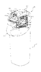
[0010] Fig. 1 is a perspective view of a container and adjustable closure
Showing the
2
CA 02693360 2009-12-18
WO 2009/063331 PCT/IB2008/003859
seal in a closed, sealed position;
[0011] Fig. 2 shows the container and adjustable closure in a partly sealed,
incipient
break position;
[0012] Fig. 3 shows the container and adjustable closure in an open position;
[0013] Fig. 4 shows the container and adjustable closure in a fully open
position;
[0014] Fig. 5 is an exploded partial side view of a container and components
of the
adjustable closure of a first embodiment of the present invention in a
disassembled
position;
[0015] Fig. 5A is side perspective view of a yoke of the adjustable closure of
the first
embodiment;
[0016] Fig. 6 is a sectioned partial side view of a container and the
adjustable closure
of the first embodiment, wherein the seal is in a closed, sealed position;
[0017] Fig. 7 shows the container and adjustable closure of Fig. 6 in a partly
sealed,
incipient break position;
[0018] Fig. 8 shows the container and adjustable closure of Figs. 6 and 7 in
an
unsealed position;
[0019] Fig. 9 shows the container and adjustable closure of Figs. 6, 7, and 8
in an
open position;
[0020] Fig. 10 shows the container and adjustable closure of Figs. 6, 7, 8,
and 9 in a
fully open position;
[0021 ] Fig. 11 is an exploded partial side view of a container and components
of the
adjustable closure of a second embodiment of the present invention in a
disassembled
position;
[0022] Fig. 12 is a cross-section of a first side perspective view of a filled
container
and the adjustable closure of the second embodiment, wherein the seal is in a
closed,
sealed position;
[0023] Fig. 13 is a top perspective view of the container and the adjustable
closure of
the second embodiment, wherein springs are removed;
[0024] Fig. 14 is second side perspective view of the container and the
adjustable
closure of the second embodiment, wherein a portion of the closure is cut
away;
[0025] Fig. 15 is a sectioned side view of the container and the adjustable
closure of
the second embodiment without the spring, wherein the closure is in a closed,
sealed
3
CA 02693360 2009-12-18
WO 2009/063331 PCT/IB2008/003859
position;
[0026] Fig. 16 shows the container and adjustable closure of Fig. 15 in an
intermediate position where the closure remains sealed;
[0027] Fig. 17 shows the container and adjustable closure of Figs. 15 and 16
in an
incipient break position;
[0028] Fig. 18 shows the container and the adjustable closure of Figs. 15, 16,
and 17
in an open, unsealed position;
[0029] Fig, 19 shows the container and the adjustable closure of Figs. 15, 16,
17, and
18 in a fully open position; and
[0030] Fig. 20 is an illustrative view of a working example of the adjustable
closure
including measurements.
DETAILED DESCRIPTION OF THE DRAWINGS
[0031] The present invention involves a closure system S that is kinematically
linked
to a container C. The container C may be any type of container having at least
one
opening 0 for providing access into the container C, such as cups, jars, cans,
bottles,
mugs, tanks, ports, and pipes. As shown in the Figs., the container C is
preferably a
beverage container for storing a beverage B. Further, the container C may also
include
a handle H, and the handle H is preferably a finger loop.
[0032] The closure S is preferably integrally formed with the container C to
seal the
opening 0 of the container C. Alternatively, the closure S may include an
attaching
means for securing the closure system S to the container C to seal the opening
O. For
example, the closure system S may include a threaded portion for screwing the
closure S onto corresponding threads surrounding the container opening O.
[0033] Further, the closure system S is moveable among different positions to
permit
various degrees of access to and from the container C via the opening O. As
shown
in Fig. 1, the closure S is in a fully closed position to seal the opening 0
of the
container C to prevent the beverage B from spilling or splashing out of the
container
C. In Fig. 2, the closure S is in an incipient break position wherein the
opening 0 is
partly unsealed. In Fig. 3, the closure S is in an open position to allow the
beverage B
to flow through the opening 0 of the container C, and in Fig. 4, the closure
system S
is in a fully open position to allow complete access of the container C via
the opening
4
CA 02693360 2009-12-18
WO 2009/063331 PCT/IB2008/003859
0.
[0034] Sectioned side views of a first embodiment of the adjustable closure
system S
are shown in Figs. 5-10. While the side views only illustrate half of the
kinematic
linkages of the closure system S, the closure S includes symmetrical linkages
on the
side not shown in the Figs. The closure S comprises a lever 1 having a locking
means 2, and the locking means 2 includes an arcuate portion 3. The closure S
also
comprises a yoke 4 having a stop 5. In addition, the closure S includes a lid
portion 6
and a resilient seal 8. The sealing 8 is preferably an elastomeric o-ring
placed in a
circumferential groove around the periphery of the lid portion 6.
[0035] The closure S also includes a link 9 having a link stop 7 and a leg 10
with a
catch 11. The link stop 7 engages the stop 5 of the yoke 4 to limit the
movement of
the link 9. Further, the closure system S utilizes spring system including a
springfront
12 and a springrear 13 that are secured to each other in a linear, sliding
relationship
along a spring 21, which urges the springfront 12 and the springrear 13 apart.
The
spring 21 is preferably a coil spring, but any suitable energy storing means
may be
used. The springfront 12 includes a latch 15 and an arm 14 for slidingly
attaching the
springfront 12 to the springrear 13.
[0036] The container C includes a pocket 16 with an arcuate portion 17. The
container further includes a sealing surface 19 and a stop 23. If the closure
S is
integrally formed with the coritainer C, then the pocket 16, the sealing
surface 19, and
the stop 23 are part of a container wall W. Alternatively, if the closure
system S is
removably secured to the container C, then the pocket 16 and the stop 23 are
formed
in a separate portion of the closure system S that is attached to the opening
O.
[0037] To form a kinematic linkage between the closure system S and the
container
C, the lever 1 is pivotally connected to the leg 10, the link 9, and the
springfront 12 at
points a, b, and c, respectively, so that the connection of the lever 1 and
the leg 10 at
point a is not concentric with the arcuate portion 3 of the locking means 2 of
the lever
1. The leg 10 is also pivotally connected to the lid portion 6 at a point d so
that the
leg 10 links the lever 1 with the lid portion 6. The lid portion 6 is also
pivotally
secured to the yoke 4 at a point e.
[0038] The yoke 4 is similarly pivotally connected to the link 9 at a point f.
Consequently, the link 9 kinematically connects.the yoke 4 with the lever 1.
The yoke
5
CA 02693360 2009-12-18
WO 2009/063331 PCT/IB2008/003859
4 is also pivotally secured to the container C at a point h, and the
springrear 13 is
likewise pivotally mounted to the container C at a point j. If the closure
system S is
integrally formed with the container C, the points h and j are located on a
container
wall W. Alternatively, if the closure S is fitted onto the container C, then
points h and
j are formed in a separate portion of the closure system S that is removably
attached to
the opening O.
[0039] In light of the linkages between the lever 1 and the yoke 4 via the
link 9 and
the yoke 4 and the container C at a pivot point h, the arcuate portion 3 of
the locking
means 2 of the lever 1 engages the arcuate portion 17 of the pocket 16 of the
container
C so that the arcuate portions 3 and 17 are concentric with each other. As a
result, the
locking means 2 cannot move within the pocket 16 other than by rotation of the
lever
1 relative to the arcuate portions 3 and 17. In an alternative embodiment, the
pocket
16 and the arcuate surface 17 are formed on the lever 1, and the locking means
2 and
the arcuate surface 3 are formed on the container C.
[0040] The pivoting connections of kinematic linkages of the components of the
closure system S and the container C may involve pins received in round
aperatures.
However, oblong slots may also be used to pivotally link the components so as
to
allow for translating movements, as well as pivoting movements. Further, the
pins
may not be sized to exactly fit the corresponding aperatures so as to provide
some
clearance between the pins and the aperatures, which also allows some
translating
movements between the components.
[0041 ] In light of the kinematic linkage between the closure S and the
container C,
the closure S is moveable among different positions to provide various degrees
of
access to and from the container C via the opening O. In other words, the
closure
system S can effectively seal the opening 0 of the container C, as well as
provide
convenient access to the beverage B within the container C and to the interior
of the
container C. Further, when the closure S is in the sealed position, the
closure S is
able to withstand an outward force caused by pressure generated by the
beverage B
within the container C.
[0042] To completely seal the opening 0 of the container C and prevent a
beverage
from flowing out of the container C, the compression spring 21 forces the
springfront
12 away from the springrear 13, which is connected to the container C at the
point j.
6
CA 02693360 2009-12-18
WO 2009/063331 PCT/IB2008/003859
Due to the pivoting connection of the springfront 12 and the lever 1 at the
point c, the
spring force of the compression spring 21 likewise urges the lever 1 in a
counterclockwise direction about the arcuate portions 3 and 17 of the lever 1
and the
pocket 16 of the container C, respectively. Consequently, when the closure S
is in the
sealed position, the lever 1 is positioned furthest away from the point j
where the
springrear 13 is connected to the container C, as shown in Fig. 6.
[0043] When the lever 1 is positioned furthest away from the point j, the
connection
of the lever 1 to the lid portion 6 via the leg 10 causes the seal 8 to slide
or roll against
the sealing surface 19 until the seal 8 is compressed against the sealing
surface 19. As
a result of the compression of the seal 8 against the sealing surface 19, any
gap
between the lid portion 6 and the container wall W is closed, and the opening
0 of the
container C is completely sealed.
[0044] To release the seal of the opening 0, the lever 1 is rotated in a
clockwise
direction toward the point j. When the lever 1 reaches a position
approximately 40
from the position shown in Fig. 6, the seal of the opening 0 is in an
incipient break
position. The kinematic linkage of the lever 1 and the lid portion 6 via the
leg 10
causes a part of the lid portion 6 located at the point d where the leg 10 is
connected
to the lid portion 6 to start to move away from an interior of the container
C.
Simultaneously, the linkage of the lever 1 and the yoke 4 via the link 9
causes a part
of the lid portion 6 located at the point e where the yoke 4 is connected to
the lid
portion 6 to start to move toward the interior of the container C, as shown in
Fig. 7.
As a result, the lid portion 6 rotates about a center of pressure 24 to
decompress the
seal 8, as well as maintain a substantially constant volume within the
container C. In
addition, in this position, the spring 21 is at a maximum compression, so
there is
essentially no torque on the lever 1.
[0045] As the lever 1 is rotated further in a clockwise direction, the
kinematic linkage
of the components of the closure system S and the container C causes the seal
8 to
further decompress until the seal 8 no longer contacts the sealing surface 19,
as
shown in Fig. 8. Consequently, a gap begins to form between the lid portion 6
and
the container wall W'and the pressure within the container C is released. Any
spray
caused by the pressure released may be retained by the yoke 4. Also in this
position,
the link stop 7 of the link 9 engages the stop 5 of the yoke 4 to arrest the
movement of 7
CA 02693360 2009-12-18
WO 2009/063331 PCT/IB2008/003859
the link 9 relative to the yoke 4.
[0046] Once the seal of the opening 0 is released, the closure system S may be
moved to an open position to allow the beverage B to flow out of the container
C. To
open the closure S, the lever 1 is further rotated in a clockwise direction
until the
lever 1 reaches a position adjacent the point j, as shown in Fig. 9. Since the
engagement of the link 7 and the stop 5 prohibit any further movement of the
link 9,
the lever 1 rotates about the point b where the lever 1 is connected to the
link 9, as
opposed to about the arcuate portions 3 and 17. However, the locking means 2
continues to rotate about the arcuate portions 3 and 17. As the lever 1
rotates about
the point b, the arcuate portion 3 of the locking means 2 is cleared from the
arcuate
portion 17 of the pocket 16 of the container C. Once the locking means 2 is
free from
the pocket 16, the sea18 is completely released from the sealing surface 19,
and gaps
are formed between the lid portion 6 and the container wall W. As a result,
the
beverage B can flow past the lid portion and out of the container C via the
opening 0
and replacement air can flow into the container C.
[0047] In addition to allowing the beverage B to flow from the container C,
the
closure system S is moveable to a fully open position to allow total access to
the
interior of the container C. In the fully open position shown in Fig. 10, the
catch 11of .
the leg 10 engages a latch 15 on the springfront 12 to prevent the lever 1
from rotating
relative to the yoke 4. As a result of the kinematic linkages between the
components,
the leg 10 and the yoke 4 rotate together about the point h where the yoke 4
is
pivotally mounted to the container C. The leg 10 and the yoke 4 are free to
rotate
about the point h until they are held in place by the stop 23 on the container
C. In
addition, the spring force of the spring 21 retains the closure system S in
the fully
open position.
[0048] A second and preferred embodiment of the adjustable closure system S is
shown in Figs. 11-17. While Figs. 12 and 15-17 only show side views of the
closure
S so that only half of the kinematic linkages of the closure system S are
visible, the
closure S includes symmetrical linkages on an opposite side, as shown in Figs.
13-14.
The closure S comprises a lever 101 having a locking means 102, and the
locking
means 102 includes two arcuate portions 103a and 103b. The radius of the
arcuate
portion 103a is smaller than the radius of the arcuate portions 103b. Further,
the
8
CA 02693360 2009-12-18
WO 2009/063331 PCT/IB2008/003859
center of the radii or arcuate portions 103a and 103b is centermark 125.
[0049] The closure S also comprises a yoke 104 having a stop 123 and an
arcuate slot
105 with an inner edge located furthest from point h. Alternatively, the slot
105 may
be a straight slot. In addition, the closure S includes a lid portion 106 and
a seal 108,
as well as a cover 109 for protecting the components of the closure system S.
[0050] The seal 108 is preferably an elastomeric, circular o-ring placed in a
circumferential groove around the periphery of the lid portion 106. As an
alternative
to a circular cross-section, the o-ring may be tapered in cross-section. In
addition, the
groove may be circular in cross- section or ovalular in cross-section so as to
allow an
circular o-ring to move therein, as shown in Fig. 12. As another alternative,
the
groove may have a V-shaped cross-section.
[0051] The closure S also includes a leg 110. Further, the closure system S
utilizes a
spring system including a springfront 112 and a springrear 113 that are
secured to
each other in a linear relationship via a spring 121, which urges the
springfront 112
and the springrear 113 apart. While the spring 121 is preferably a buckled
column
composed of a leaf of spring steel loaded endwise, any suitable type of spring
or
energy storage device may be used. Further, the a stop 122 is secured to the
springfront 112 to cover the springfront 112.
[0052] The container C includes a pocket 116 with two arcuate portions 117a
and
11 7b. The radius of the arcuate portion 117a is smaller than the radius of
the arcuate
portions 11 7b. Further, the center of the radii or arcuate portions 11 7a and
117b is
centermark 126. The container further includes a sealing surface 119. If the
closure S
is integrally formed with the container C, then the pocket 116 and the sealing
surface
119 are part of a container wall W. Alternatively, if the closure system S is
removably secured to the container C, then the pocket 116 is formed in a
separate
portion of the closure system S that is attached to the opening O.
[0053] To form a kinematic linkage between the closure system S and the
container
C, the lever 101 is pivotally connected to the leg 110, the slot 105 of the
yoke 104,
and the springfront 112 at points a, b, and c, respectively, so that the
connection of the
lever 101 and the leg 110 at the point a is not necessarily concentric with
the arcuate
portion 103a of the locking means 102 of the lever 101. The leg 110 is also
pivotally
connected to the lid portion 106 at a point d so that the leg 110 links the
lever 101
9
CA 02693360 2009-12-18
WO 2009/063331 PCT/IB2008/003859
with the lid portion 106. The lid portion 106 is also pivotally secured to the
yoke 104
at a point e.
[0054] The yoke 104 is also pivotally secured to the container C at a point h,
and the
springrear 113 is likewise pivotally mounted to the container C at a point j.
If the
closure system S is integrally formed with the container C, the points h and j
are
located on a container wall W. Alternatively, if the closure S is fitted onto
the
container C, then points h and j are formed in a separate portion of the
closure system
S that is removably attached to the opening 0.
[0055] In light of the linkages between the lever 101 and the yoke 104 via the
slot
105 at the point b and the yoke 104 and the container C at a pivot point h,
the arcuate
portion 103a of the locking means 102 of the lever 101 engages the arcuate
portion
117a of the pocket 116 of the container C so that the arcuate portions 103a
and 117a
are concentric with each other and the centermarks 125 and 126 align. As a
result, the
locking means 102 cannot move within the pocket 116 other than by rotation of
the
lever 101 relative to the arcuate portions 103a and 117a. In an alternative
embodiment, the pocket 116 and the arcuate surfaces 117a and 117b are formed
on
the lever 101, and the locking means 102 and the arcuate surfaces 103a and
103b are
formed on the container C.
[0056] Like the first embodiment, the pivoting connections of kinematic
linkages of
the components of the second embodiment of the closure system S and the
container
C may involve pins received in round aperatures. However, oblong slots may
also be
used to pivotally link the components so as to allow for translating
movements, as
well as pivoting movements. Further, the pins may not be sized to exactly fit
the
corresponding aperatures so as to provide some clearance between the pins and
the
aperatures, which also allows some translating movements between the
components.
[0057] In light of the kinematic linkage between the closure S and the
container C,
the closure S is moveable among different positions to provide various degrees
of
access to and from the container C via the opening O. In other words, the
closure
system S can effectively seal the opening 0 of the container C, as well as
provide
convenient access to the beverage B within the container C and to the interior
of the
container C. Further, when the closure S is in the sealed position, the
closure S is
able to withstand any outward force caused by pressure generated by the
beverage B
CA 02693360 2009-12-18
WO 2009/063331 PCT/IB2008/003859
within the container C.
[0058] To completely seal the opening 0 of the container C and prevent a
beverage B
from flowing out of the container C, the spring 121 forces the springfront 112
away
from the springrear 113, which is connected to the container C at the point j.
Due to
the pivoting connection of the springfront 112 and the lever 101 at the point
c, the
spring force of the spring 121 likewise urges the lever 101 in a
counterclockwise
direction about the arcuate portions 103a and 117a of the lever 101 and the
pocket
116 of the container C, respectively. Consequently, when the closure S is in
the
sealed position, the lever 101 is positioned furthest away from the point j
where the
springrear 113 is connected to the container C, as shown in Fig. 15.
[0059] When the lever 101 is positioned furthest away from the point j, the
connection of the lever 101 to the lid portion 106 via the leg 110 causes the
seal 108
to slide or roll against the sealing surface 119 until the seal 108 is
compressed against
the sealing surface 119. As a result of the compression of the seal 108
against the
sealing surface 119, any gap between the lid portion 106 and the container
wall W is
closed, and the opening 0 of the container C is completely sealed.
[0060] To release the seal of the opening 0, the lever 101 is rotated in a
clockwise
direction toward the point j. As the lever 101 moves from the position shown
in Fig.
15 to the position shown in Fig. 16, the point b moves away from an inner edge
of the
slot 105 of the yoke 104. As the lever 101 is further rotated in the clockwise
direction, the kinematic linkage of the lever 101 and the lid portion 106 via
the leg
110 causes a part of the lid portion 106 located at the point d where the leg
110 is
connected to the lid portion 106 to begin to move away from the interior of
the
container C. Simultaneously, the linkage of the lever 101 and the yoke 104 via
the
slot 105 at the point b causes a part of the lid portion 106 located at the
point e where
the yoke 104 is connected to the lid portion 106 to start to move toward the
interior of
the container C, as shown in Fig. 17. As a result, the lid portion 106 rotates
about a
center of pressure 124 to decompress the seal 108, as well as maintain a
constant
volume within the container C. In addition, the point b returns to the inner
edge of
the slot 105, as also shown in Fig. 17.
[0061] As the lever 101 is rotated further in a clockwise direction, the
kinematic
linkage of the components of the closure system S and the container C causes
the seal
11
CA 02693360 2009-12-18
WO 2009/063331 PCT/IB2008/003859
108 to further decompress until the seal 108 no longer contacts the sealing
surface
119, as shown in Fig. 18. Consequently, a gap begins to form between the lid
portion
106 and the container wall W and the pressure within the container C is
released.
Any spray caused by the pressure released is retained by the cover 109.
[0062] Once the seal of the opening 0 is released, the closure system S may be
moved to an open position to allow the beverage B to flow out of the container
C. To
open the closure S, the lever 101 is further rotated in a clockwise direction
until the
lever 101 reaches a position adjacent the point j, as shown in Fig. 19. The
slot 105 of
the yoke 104 prohibits any further movement of yoke 104, and the lever 101
rotates
about the point b where the lever 101 is connected to the slot 105 of the yoke
104, as
opposed to about the arcuate portions 103a and 117a. However, the locking
means
102 continues to rotate about the arcuate portions 103a and 117a. As the lever
101
rotates about the point b, the arcuate portion 103a of the locking means 2 is
cleared
from the arcuate portion 11 7a of the pocket 116 of the container C. Once the
locking
means 102 is free from the pocket 116, the seal 108 is completely released
from the
sealing surface 119, and gaps are formed between the lid portion 6 and the
container
wall W. As a result, the beverage B can flow past the lid portion and out of
the
container C via the opening 0, as shown in Fig. 18.
[0063] In addition to allowing the beverage B to flow from the container C,
the
closure system S is moveable to a fully open position to allow total access to
the
interior of the container C. In the fully open position shown in Fig. 19, the
stop 122
contacts the stop 123 of the yoke 104 to prevent the lever 101 from
inadvertent
actuation. In addition, the spring force of the spring 121 retains the closure
system S
in the fully open position.
[0064] In light of the numerous components of the closure S and the container
C and
the pivoting connections therebetween, there are a number of possible
dimensions and
orientation for these components which would effectively seal the opening 0 of
the
container C. An example of one such working model of the preferred embodiment
of
the sealing sytem S is depicted in Fig. 18. In Fig. 18, the measurements are
relative to
an origin X.
[0065] The foregoing description of the present invention has been presented
to
illustrate the principles of the invention and not to limit the invention to
the particular
12
CA 02693360 2009-12-18
WO 2009/063331 PCT/IB2008/003859
embodiments illustrated. It is intended that the scope of the invention be
defined by
all of the embodiments encompassed within the following claims and their
equivalents.
13