Language selection

Search

Patent 2693573 Summary

Third-party information liability

Some of the information on this Web page has been provided by external sources. The Government of Canada is not responsible for the accuracy, reliability or currency of the information supplied by external sources. Users wishing to rely upon this information should consult directly with the source of the information. Content provided by external sources is not subject to official languages, privacy and accessibility requirements.

Claims and Abstract availability

Any discrepancies in the text and image of the Claims and Abstract are due to differing posting times. Text of the Claims and Abstract are posted:

  • At the time the application is open to public inspection;
  • At the time of issue of the patent (grant).
(12) Patent: (11) CA 2693573
(54) English Title: ASSEMBLY OF TURRET AND DISCONNECTABLE BUOY
(54) French Title: ENSEMBLE DE TOURELLE ET DE BOUEE DECONNECTABLE
Status: Granted and Issued
Bibliographic Data
Abstracts

English Abstract


Assembly of turret and disconnectable buoy, in which the turret at its lower
end
and the buoy at its upper end are provided with mating coupling provisions.
The coupling
provisions comprise an annular projection protruding from one of the turret
and buoy towards the
other of the turret and buoy and a correspondingly shaped annular recess on
the other of the
turret and buoy for receiving the annular projection. The annular projection
has a base which is
wider than a top thereof, whereas the annular recess has a top which is wider
than a base
thereof.


French Abstract

L'invention concerne un ensemble de tourelle (2) et de bouée déconnectable (3). L'extrémité inférieure la tourelle et l'extrémité supérieure la bouée comportent des éléments d'accouplement correspondants. Les éléments d'accouplement comprennent une saillie annulaire (4) faisant saillie soit de la tourelle soit de la bouée en direction soit de la bouée soit la tourelle ; une cavité annulaire de forme correspondante (5) sur soit la bouée soit la tourelle pour recevoir la saillie annulaire. La saillie annulaire est munie d'une base (6) qui est plus large que sa partie supérieure (7) ; la cavité annulaire est munie d'une partie supérieure (8) plus large que sa base (9).

Claims

Note: Claims are shown in the official language in which they were submitted.

CLAIMS
1. Assembly of turret and disconnectable buoy, in which the turret at its
lower end
and the buoy at its upper end are provided with mating coupling provisions,
characterized in
that the coupling provisions comprise an annular projection protruding from
one of the turret
and buoy towards the other of the turret and buoy and a correspondingly shaped
annular recess
on the other of the turret and buoy for receiving the annular projection,
wherein the annular pro-
jection has a base which is wider than a top thereof, whereas the annular
recess has a top
which is wider than a base thereof.
2. Assembly according to claim 2, wherein the cross-section of the annular pro-
jection and annular recess has a trapezoidal shape.
3. Assembly according to claim 1 or 2, wherein the annular projection is
provided
on the buoy whereas the annular recess is provided in the turret.
4. Assembly according to any of the previous claims, wherein a sealing member
is provided between the annular projection and the annular recess.
5. Assembly according to claim 4, wherein the sealing member is provided be-
tween the top of the annular projection and the base of the annular recess.
6. Assembly according to claim 5, wherein the sealing member is attached to
the
base of the annular recess.
7. Assembly according to any of the claims 4-6, wherein the seal member is a
soft rubber or mild steel ring.
5

Description

Note: Descriptions are shown in the official language in which they were submitted.


CA 02693573 2010-01-14
Agent Ref: 71858/00010
1 Assembly of Turret and Disconnectable Buoy
2 The invention relates to an assembly of turret and disconnectable buoy, in
which
3 the turret at its lower end and the buoy at its upper end are provided with
mating coupling provi-
4 sions.
In offshore oil production, use is made of so called FPSO's (Floating
Production,
6 Storage and Offloading). FPSO's are ships which are permanently or semi-
permanently an-
7 chored offshore at an oilfield for the purpose of receiving well fluids from
the oil reservoir, sepa-
8 rating the oil from the water and gas and storing the oil on board for later
transfer to another
9 vessel. Generally, the FPSO's are anchored by means of single point mooring
systems of the
internal or external turret type.
11 In some areas of the world, weather conditions can deteriorate so badly,
such as
12 due to hurricanes, that it is required to enable the FPSO to disconnect
from its anchoring sys-
13 tem and sail temporarily to safer waters. Likewise, in iceberg infested
waters it is sometimes
14 necessary to disconnect the FPSO to avoid damage to the vessel.
In these instances use is made of an disconnectable turret mooring system,
16 which can be of the internal or the external type (in the one case the
turret is fitted within the
17 confines of the vessel hull, in the other case the turret is fitted forward
of the bow of the vessel),
18 comprising a disconnectable buoy, wherein the turret at its lower end and
the buoy at its upper
19 end are provided with mating coupling provisions.
In the design of a disconnectable turret particular care needs to be given to
the
21 interface between the lower end of the turret and the upper end of the
disconnectable buoy.
22 Ideally this interface is preloaded in such a way as to avoid that a gap is
created
23 between the turret and the buoy under external anchoring and wave load
conditions. Since gen-
24 erally the turret and the buoy are cilindrical or conical structures with a
large diameter, it is also
important to interlock these structures in such a way that both act as a
single structure when
26 connected. Another objective is to achieve a good fit between the
structures at their interface,
27 without resorting to tight and hence expensive machining tolerances.
28 The assemblies according to the state of the art provide a buoy with a
protruding
29 conical upper end which has to be received in a correspondingly shaped
conical lower recess of
the turret. These known assemblies suffer from the significant drawback that
whereas the coni-
31 cal interface eases fit up of the two structures, the conical recess must
be fabricated extremely
32 heavy and sturdy to resist the radial loads which follow from the two parts
being connected.
21956434.1 1

CA 02693573 2010-01-14
Agent Ref: 71858/00010
1 Very significant preload is required to assure that the buoy and turret do
not separate under
2 external loads arising from anchoring and waves. If such preload cannot be
achieved suffi-
3 ciently, locking means, which connect the disconnectable buoy to the turret,
are subject to high
4 cyclic load variations following from these anchoring and wave loads and
hence may fail prema-
turely.
6 The objectives of this invention are met by an assembly of turret and
disconnect-
7 able buoy, in which the turret at its lower end and the buoy at its upper
end are provided with
8 mating coupling provisions, characterized in that the coupling provisions
comprise an annular
9 projection protruding from one of the turret and buoy towards the other of
the turret and buoy
and a correspondingly shaped annular recess on the other of the turret and
buoy for receiving
11 the annular projection, wherein the annular projection has a base which is
wider than a top
12 thereof, whereas the annular recess has a top which is wider than a base
thereof.
13 Preferred embodiments of the assembly in accordance with the present
invention
14 are subject of the depending claims.
The annular projection and annular recess are machined to a tolerance such
that
16 if they are engaged one to another, under an axial compression force, one
of these parts de-
17 forms more than the other in a radial direction such as to become compliant
with the other part
18 in a form-fit.
19 By applying a nominal preload to this interface, both parts of the assembly
now work as one
single part, there being no tendency for the engaged parts to separate.
21 The tolerances of machining are selected such that the diameter growth of
the
22 weakest part, typically the lower end of the turret structure, under a
compression force, is limited
23 to such a percentage of tangential elongation that it avoids achieving the
yield stress of the ma-
24 terial (steel) being employed in the parts. Once this stress level is
reached, a further increase of
the compressive force merely increases loacal stresses in the radial section
of the parts and
26 increases the contact stresses between these parts. This is a very stiff
load path, with locking
27 means which connect the disconnectable buoy to the turret forming part of a
much lesser stiff
28 load path. Hence these locking means are not subject to any significant
cyclic loads .
29 Since a very high internal contact stress is achieved over the tapering
surfaces of the projection
and recess, these parts can also act as a sealing device against the seawater
to allow the turret
31 to be pumped dry after a connect operation. An additional sealing member
(e.g. a soft rubber or
32 mild steel ring) may be fitted between the annular projection and annular
recess.
21956434.1 2

CA 02693573 2010-01-14
Agent Ref: 71858/00010
1 The invention will be elucidated while referring to the drawing, in which:
2 Fig. 1 shows schematically a typical FPSO with an internal turret being
anchored
3 to the seabed in a manner known per se using a disconnectable buoy;
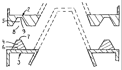
4 Fig. 2 shows schematically and on an enlarged scale the interface between a
turret and disconnectable buoy; and
6 Fig. 3 shows schematically an embodiment with additional sealing member.
7 Referring to figure 1, a FPSO 1 is shown which, in a manner known per se, is
8 provided with an internal turret 2 which, at its lower end, is connected to
a disconnectable buoy
9 3. The buoy 3 is anchored to the bottom of the sea 4 by means of anchor
lines 5, whereas a
production line 6 is connected between a well bore 7 and the buoy 3 (and leads
further through
11 the turret towards an appropriate on-board installation, not shown).
12 Referring to figure 2, the interface between the lower end of the turret 2
and the
13 upper end of the disconnectable buoy 3 is illustrated schematically in a
longitudinal cross sec-
14 tion and in a situation before being assembled. As shown, the upper end of
the buoy 3 is pro-
vided with an annular projection 4 protruding from the buoy, whereas the lower
end of the turret
16 is provided with a correspondingly shaped annular recess 5 for receiving
the annular projection
17 4. The annular projection has a base 6 which is wider than a top 7 thereof,
wheras the annular
18 recess has a top (mouth) 8 which is wider than a base 9 thereof.
Specifically, in the illustrated
19 embodiment, the cross-section of the annular projection and annular recess
has a trapezoidal
shape. As a result assembling these parts (i.e. entering the annular
projection 4 into the annular
21 recess 5) is very easy and leads to an optimised load path between the
turret 2 and buoy 3.
22 It is possible too that the annular projection is part of the turret and
that the annu-
23 lar recess is provided in the buoy. Further it is conceivable to provide
more than one annular
24 projection with corresponding annular recess; in such a case it would be
possible that each of
the turret and buoy comprises at least one annular projection and at least one
annular recess.
26 It is noted that the provision of an annular projection and annular recess
does not
27 prevent that, in accordance with the state of the art, the lower end of the
turret 2 and upper end
28 of the buoy have corresponding tapering shapes (as indicated schematically
in figure 2 by dot-
29 ted lines).
Finally figure 3 represents on a larger scale a sealing member 10
interpositioned
31 between an annular projection 4 and an annular recess 5. Specifically the
sealing member 10 is
32 provided between the top 7 of the annular projection 4 and the base 9 of
the annular recess 5.
21956434.1 3

CA 02693573 2010-01-14
Agent Ref: 71858/00010
1 Preferably the sealing member is attached to the base 9 of the annular
recess. The seal mem-
2 ber may compise a soft rubber or mild steel ring.
3 The invention is not limited to the embodiments described before, which may
be
4 varied widely within the scope of the invention as defined by the appending
claims.
21956434.1 4

Representative Drawing
A single figure which represents the drawing illustrating the invention.
Administrative Status

2024-08-01:As part of the Next Generation Patents (NGP) transition, the Canadian Patents Database (CPD) now contains a more detailed Event History, which replicates the Event Log of our new back-office solution.

Please note that "Inactive:" events refers to events no longer in use in our new back-office solution.

For a clearer understanding of the status of the application/patent presented on this page, the site Disclaimer , as well as the definitions for Patent , Event History , Maintenance Fee  and Payment History  should be consulted.

Event History

Description Date
Change of Address or Method of Correspondence Request Received 2020-10-23
Inactive: Associate patent agent added 2020-04-29
Appointment of Agent Request 2020-03-17
Revocation of Agent Requirements Determined Compliant 2020-03-17
Appointment of Agent Requirements Determined Compliant 2020-03-17
Revocation of Agent Request 2020-03-17
Common Representative Appointed 2019-10-30
Grant by Issuance 2014-01-07
Inactive: Cover page published 2014-01-06
Pre-grant 2013-10-08
Inactive: Final fee received 2013-10-08
Notice of Allowance is Issued 2013-08-30
Letter Sent 2013-08-30
Inactive: Approved for allowance (AFA) 2013-08-26
Letter Sent 2012-07-05
Request for Examination Requirements Determined Compliant 2012-06-19
All Requirements for Examination Determined Compliant 2012-06-19
Request for Examination Received 2012-06-19
Letter Sent 2011-06-02
Inactive: Single transfer 2011-05-13
Inactive: Cover page published 2010-03-31
Inactive: Notice - National entry - No RFE 2010-03-18
Application Received - PCT 2010-03-16
Inactive: IPC assigned 2010-03-16
Inactive: First IPC assigned 2010-03-16
National Entry Requirements Determined Compliant 2010-01-14
Application Published (Open to Public Inspection) 2009-01-22

Abandonment History

There is no abandonment history.

Maintenance Fee

The last payment was received on 2013-06-19

Note : If the full payment has not been received on or before the date indicated, a further fee may be required which may be one of the following

  • the reinstatement fee;
  • the late payment fee; or
  • additional fee to reverse deemed expiry.

Patent fees are adjusted on the 1st of January every year. The amounts above are the current amounts if received by December 31 of the current year.
Please refer to the CIPO Patent Fees web page to see all current fee amounts.

Owners on Record

Note: Records showing the ownership history in alphabetical order.

Current Owners on Record
BLUEWATER ENERGY SERVICES B.V.
Past Owners on Record
JACOB DE BAAN
Past Owners that do not appear in the "Owners on Record" listing will appear in other documentation within the application.
Documents

To view selected files, please enter reCAPTCHA code :


To view images, click a link in the Document Description column. To download the documents, select one or more checkboxes in the first column and then click the "Download Selected in PDF format (Zip Archive)" or the "Download Selected as Single PDF" button.

List of published and non-published patent-specific documents on the CPD .

If you have any difficulty accessing content, you can call the Client Service Centre at 1-866-997-1936 or send them an e-mail at CIPO Client Service Centre.


Document
Description 
Date
(yyyy-mm-dd) 
Number of pages   Size of Image (KB) 
Description 2010-01-13 4 184
Drawings 2010-01-13 1 20
Abstract 2010-01-13 1 14
Claims 2010-01-13 1 30
Representative drawing 2010-03-30 1 9
Abstract 2013-08-29 1 14
Representative drawing 2013-12-04 1 8
Notice of National Entry 2010-03-17 1 195
Courtesy - Certificate of registration (related document(s)) 2011-06-01 1 103
Reminder - Request for Examination 2012-03-18 1 116
Acknowledgement of Request for Examination 2012-07-04 1 188
Commissioner's Notice - Application Found Allowable 2013-08-29 1 163
PCT 2010-01-13 3 110
Fees 2011-06-20 1 203
Correspondence 2013-10-07 3 86