Note: Descriptions are shown in the official language in which they were submitted.
.CA 02693687 2012-03-28
MECHANICAL AND FLUID JET DRILLING METHOD AND APPARATUS
BACKGROUND OF THE INVENTION
1. Field of the Invention
[00021 The invention relates generally to the field of excavation of
subterranean formations.
More specifically, the present invention relates to a method and apparatus of
excavating using
a self-contained system disposable within a wellbore. The present invention
involves a
method and apparatus for excavating using ultra-high pressure fluids. Though
the subject
invention has many uses, one of its primary uses is to perforate a well and/or
stimulate
production in that well.
2. Description of Related Art
[00031 Wellbores for use in subterranean extraction of hydrocarbons generally
comprise a
primary section running in a substantial vertical direction along its length.
Secondary
wellbores may be formed from the primary wellbore into the subterranean rock
formation
surrounding the primary wellbore. The secondary wellbores are usually formed
to enhance
the hydrocarbon production of the primary wellbore and can be excavated just
after formation
of the primary wellbore. Alternatively, secondary wellbores can be made after
the primary
wellbore has been in use for some time. Typically the secondary wellbores have
a smaller
diameter than that of the primary wellbores and are often formed in a
substantially horizontal
orientation.
1
CA 02693687 2010-01-11
WO 2008/157185 PCT/US2008/066592
[0004] In order to excavate a secondary wellbore, numerous devices have been
developed for
lateral or horizontal drilling within a primary wellbore. Many of these
devices include a
means for diverting a drill bit from a vertical to a horizontal direction.
These means include
shoes or whipstocks that are disposed within the wellbore for deflecting the
drilling means
into the formation surrounding the primary wellbore. Deflecting the drilling
means can
enable the formation of a secondary wellbore that extends from the primary
wellbore into the
surrounding formation. Examples of these devices can be found in Buckman, U.S.
Patent No.
6,263,984, McLeod et al., U.S. Patent No. 6,189,629, Trueman et al., U.S.
Patent No.
6,470,978, Hataway U.S. Patent No. 5,553,680, Landers, U.S. Patent No.
6,25,949, Wilkes,
Jr. et al., U.S. Patent No. 5,255,750, McCune et al., U.S. Patent No.
2,778,603, Bull et al.,
U.S. Patent No. 3,958,649, and Johnson, U.S. Patent No. 5,944,123. One of the
drawbacks of
utilizing a diverting means within the wellbore however is that the extra step
of adding such
means within the wellbore can have a significant impact on the expense of such
a drilling
operation.
[0005] Other devices for forming secondary wellbores include
mechanical/hydraulic devices
for urging a drill bit through well casing, mechanical locators, and a tubing
bending
apparatus. Examples of these devices can be found in Mazorow et al., U.S.
Patent No.
6,578,636, Gipson, U.S. Patent No. 5,439,066, Allarie et al., U.S. Patent No.
6,167,968, and
Sallwasser et al., U.S. Patent No. 5,687,806. Shortcomings of the mechanical
drilling devices
include the limited dimensions of any secondary wellbores that may be formed
with these
devices. Drawbacks of excavating devices having mechanical locators and/or
tubing bending
include the diminished drilling rate capabilities of those devices. Therefore,
there exists a
need for a device and method for excavating secondary wellbores, where the
excavation
process can be performed in a single step and without the need for positioning
diverting
2
CA 02693687 2012-03-28
devices within a wellbore previous to excavating. There also exists a need for
a device that can efficiently
produce secondary wellbores at an acceptable rate of operation.
BRIEF SUMMARY OF THE INVENTION
[0006] Disclosed herein is an exaction system comprising, a casing excavation
device, a wellbore
formation excavation device, and an ultra-high pressure source. The ultra-high
pressure source provides
fluid pressurized to an ultra-high pressure to the wellbore formation
excavation device. Ultra-high
pressure fluid can also be provided to the casing excavation device. The
casing excavation device may
comprise a drill bit, a milling device, a fluted drill bit, or a rotary drill.
The casing and the wellbore
formation excavation devices may be disposed on an arm that is extendable from
the excavation system for
excavating contact with a casing and formation.
[0006a] Accordingly, in one aspect there is provided a method of cased
wellbore excavation comprising:
disposing an excavation system within the wellbore, the system comprising a
housing, first and
second pump units in the housing, a first extendable arm in communication with
the first pump unit and
extendable from the housing, and a second extendable arm in communication with
the second pump unit
and extendable from the housing;
forming a passageway through a wellbore casing with the first arm; and
excavating through the passageway into a formation around the wellbore casing
by rotatingly contacting
the formation with the second arm and discharging ultra-high pressure fluid
from the second arm towards
the formation.
BRIEF DESCRIPTION OF THE SEVERAL VIEWS OF THE DRAWINGS
[0007] FIG. I depicts in partial cross sectional view one embodiment of an
excavation system.
[0008] FIG. 2 illustrates in partial cross sectional view an embodiment of an
excavation system in an
extended position.
[0009] FIG. 3 illustrates in partial cross sectional view an embodiment of an
excavation system in an
extended position.
[0010] FIG. 4 is a partial cutaway view of a side view of an embodiment of an
excavation.
[0011] FIG. 5 is a side view of an arm of one embodiment of an excavation
system.
[0012] FIG. 6 is a cross sectional view of a portion of an arm of an
embodiment of an excavation system.
3
CA 02693687 2010-01-11
WO 2008/157185 PCT/US2008/066592
[0013] FIG. 7 illustrates a side view of a portion of an arm of an excavation
system.
[0014] FIG. 8 depicts an embodiment of an excavation system in a deviated
portion of a
wellbore.
[0015] FIG. 9 is a cross sectional view of an embodiment of an excavation
system having an
orientation system.
DETAILED DESCRIPTION OF THE INVENTION
[0016] The present invention includes a method and apparatus useful for
excavating and
forming subterranean wellbores, including secondary wellbores extending
laterally or
transverse from a primary wellbore. With reference to FIG. 1, one embodiment
of an
excavation system 20 of the present invention is shown disposed within a
wellbore 12. The
wellbore 12 is formed through a portion of a subterranean formation 10, the
outer
circumference of the wellbore 12 is lined with casing 17 that separates the
wellbore 12 from
the formation 10. This embodiment comprises a body 11 housing a first and a
second
excavation device (2, 3). Each excavation device (2, 3) comprises a drive
means (4, 5), a
shaft (6, 7) connected on one end to the drive means, and an excavating member
(8, 9)
disposed on the end of the shaft opposite the drive means (4, 5). An aperture
13 is shown
formed on the body 11.
[0017] The excavation system 20 may be conveyed into and out of the wellbore
12 by
wireline (not shown). The wireline may also provide a command control delivery
means to
the excavation system for activating, operating, de-activating, or otherwise
controlling the
excavation system. Other conveyance and delivery means include tubing, coiled
tubing,
slickline, and drill string.
4
CA 02693687 2010-01-11
WO 2008/157185 PCT/US2008/066592
[0018] In the embodiment of FIG. 2, the first excavation device 2 is shown
excavating away a
portion of the casing 17. This is accomplished by rotating the excavating
member 8 while
simultaneously pushing the excavating member 8 against the casing 17. The
motive power
for both the rotation and pushing of the excavating member 8 may be provided
via the drive
means 4. Additionally, the force needed to extend the shaft 6 for engaging the
excavating
member 8 with the casing 17 may also be provided by the drive means 4. The
aperture 13 is
provided to allow the excavating member 8 to extend from within the body 11 to
the casing
17. In the embodiment of FIG. 2, the excavating member 8 is utilized primarily
for forming a
passageway through a portion of the casing 17. The excavating member 8 may
comprise a
drill bit, a fluted carbide end mill with radiused edges, a rotary drill bit,
diamond encrusted
bits, as well as a milling device.
[0019] With reference now to FIG. 3, the second excavating device 3 is shown
excavating a
passage 18 that initiates at the wellbore 12 and extends into the surrounding
formation 10.
Excavation of the passage 18 occurs by pressing the excavating member 9
against the
formation 10 while at the same time rotating the excavating member 9. Both the
pressing
force and rotation of the excavating member 9 may be supplied by the drive
means 5. In the
embodiment of FIGS. 2 and 3, the excavating member 9 is used primarily for
excavating
formation material, and not the casing 17. By relegating the excavating member
8 to the
removal of casing material and the excavating member 9 to formation
excavation, the design
and material of these respective members can be chosen to better suit their
specific
applications. Examples of the excavating member 9 may include a drill bit, a
fluted carbide
end mill with radiused edges, a rotary drill bit, diamond encrusted bits, as
well as a milling
device. It should be pointed out however that the second excavating device 3
may be used to
remove the casing material and the first excavation device 2 may be used to
form the passage
5
CA 02693687 2010-01-11
WO 2008/157185 PCT/US2008/066592
18 through the formation 10. Within the context of this disclosure, excavation
includes
drilling, milling, punching, piercing, perforating, boring, and any other act
of removing
material.
[0020] The drive means (4, 5) may comprise a motor, such as an electrically
powered motor
or a mud motor powered by the hydraulic pressure of downhole fluids. The drive
means as
shown is disposed within the wellbore 12 proximate to the excavation system 20
and directly
coupled to the shaft or at the surface. However alternative embodiments exist
wherein the
drive means is disposed at surface. Optionally, a hydraulic pump as well as an
intensifier (not
shown) may be included with the excavation system 20 of FIGS. 1-3 for
delivering ultra-high
pressure fluid to the excavating members (8, 9) to aid in their excavation. In
one embodiment
the ultra-high pressure fluid travels via a conduit within the shaft to its
respective excavating
member. During excavation the ultra-high pressure exits through a nozzle
formed on or
proximate to the cutting tip of the excavating member. Injecting ultra-high
pressure fluid
onto the material being excavated aids in the excavation process as well as
the removal of
cutting debris.
[0021] In the embodiment of FIG. 4, the excavation system also comprises a
first excavation
device 2a and a second excavation system 3a both disposed within a housing. In
this
embodiment the excavation device 2a comprises a motor 22 in mechanical
cooperation with a
pressurized fluid source disposed within a housing 21. The pressurized fluid
source of FIG. 4
is a pump unit 24. A conduit 28 is shown connected on one end to the discharge
of the pump
unit 24 and on the other end to an excavating member 50. An optional
intensifier 26 is
included, that in cooperation with the pump unit 24, increases the pressure of
the fluid exiting
the pump unit 24. The pump unit 24, either by itself or in combination with
the intensifier 26,
is capable of pressurizing fluid to ultra-high pressures. For the purposes of
this disclosure,
6
CA 02693687 2010-01-11
WO 2008/157185 PCT/US2008/066592
ultra-high pressures are those that exceed 1500 pounds per square inch (1.03E7
Pa) above the
well bore or hydrostatic pressure. An arm 31 is provided that houses a length
of the conduit
28; the arm 31 terminates at the excavating member 50. The conduit 28 provides
a fluid flow
path from the discharge of the pump unit 24 or optional intensifier 26 to the
excavating
member 50. The conduit 28 can be comprised of hose, flexible hose, tubing,
flexible tubing,
ducting, or any other suitable means of conveying a flow of pressurized fluid.
[0022] In the embodiment of FIG. 4, the motor 22 is adjacent to the pump unit
24 and an
integral part of the excavation system 20a. The motor 22 may be an electric
motor driven by
an electrical source (not shown) located at the surface above the wellbore
12a, though the
electrical source could also be situated somewhere within the wellbore 12a,
such as proximate
to the motor 22. Alternatively, the electrical source could comprise a battery
combined with
or adjacent to the motor 22. Types of motors other than electrical, such as a
mud motor, can
be employed with the present invention. Optionally, the motor 22 could be
placed above the
surface of the wellbore 12a and connected to the pump unit 24 via a crankshaft
(not shown).
It is well within the capabilities of those skilled in the art to select,
design, and implement
types of motors that are suitable for use with the present invention.
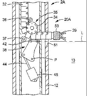
[0023] With reference now to the arm 31 of the embodiment of the invention of
FIG. 4, it is
comprised of a series of generally rectangular segments 32. As seen in FIG. 7,
each segment
32 includes a tab 39 (more preferably a pair of tabs 39 disposed on opposite
and
corresponding sides of the segment 32) extending outward from the rectangular
portion of the
segment 32 and overlapping a portion of the adjoining segment 32. An aperture
41, capable
of receiving a pin 33, is formed through each tab 39 and the portion of the
segment 32 that the
tab 39 overlaps. Positioning the pin 33 through the aperture 41 secures the
tab 39 to the
overlapped portion of the adjoining segment 32 and pivotally connects the
adjacent segments
7
CA 02693687 2010-01-11
WO 2008/157185 PCT/US2008/066592
32. Strategically positioning the tabs 39 and apertures 41 on the same side of
the arm 31
results in an articulated arm 31 that can be flexed by pivoting the individual
segments 32. An
excavating member 50 is provided on the free end of the arm 31. As will be
described in
more detail below, flexure of the arm 31 enables the excavating member 50 to
be put into a
position suitable for excavation. The segments 32 can optionally have non-
rectangular cross
sectional shapes, such as circular, elliptical, and rhomboidal.
[0024] The excavation system 20a can be partially or wholly submerged in the
fluid 15 of the
wellbore 12a. The fluid 15 can be any type of liquid, including water, brine,
diesel, alcohol,
water-based drilling fluids, oil-based drilling fluids, and synthetic drilling
fluids. In one
embodiment, the fluid 15 is the fluid that already exists within the wellbore
12a prior to
insertion or operation of the excavating system 20a. Accordingly, one of the
many
advantages of this device is its ability to operate with clean fluid as well
as fluid having
entrained foreign matter.
[0025] In an alternative embodiment, the wellbore 12a is filled with an
etching acidic
solution to accommodate the operation. In such a scenario, the acid used may
be any type of
acid used for stimulating well production, including hydrofluoric or
hydrochloric acid at
concentrations of approximately 15% by volume. Though the type of fluid used
may vary
greatly, those skilled in the art will appreciate that the speed and
efficiency of the drilling will
depend greatly upon the type and characteristics of the fluid employed.
Accordingly, it may
be that liquid with a highly polar molecule, such as water or brine, may
provide additional
drilling advantage.
[0026] As previously noted, the excavation device 2a of FIG. 4 is at least
partially submerged
within wellbore fluid 15, the pump unit 24 includes a suction side in fluid
communication
with the wellbore fluid 15. During operation, the pump unit 24 receives the
wellbore fluid 15
8
CA 02693687 2010-01-11
WO 2008/157185 PCT/US2008/066592
through its suction side, pressurizes the fluid, and discharges the
pressurized fluid into the
conduit 28. While the discharge pressure of the pump unit 24 can vary
depending on the
particular application, the pump unit 24 should be capable of producing
pressures sufficient to
aid in subterranean excavation by lubricating the excavating member 50 and
clearing away
cuttings produced during excavation. The pump unit 24 can be comprised of a
single fluid
pressurizing device or a combination of different fluid pressurizing devices.
The fluid
pressurizing units that may comprise the pump unit 24 include, an intensifier,
centrifugal
pumps, swashplate pumps, wobble pumps, a crankshaft pump, and combinations
thereof.
[0027] As with the embodiments of FIGS. 1-3, the first and second excavation
devices (2a,
3a) of the embodiment of FIG. 4 can be used either for the removal of casing
material,
formation material, or both. The arm 31 of FIG. 4 is shown in a retracted
position, launching
the arm 31 into the operational mode involves guiding the excavating member 50
first
through the aperture 51. An example of an operational mode of the excavation
device 2a is
provided in FIG. 5. The arm 31 may be extended outward such that the
excavation member
50 exits the housing 21 into excavating contact with either the casing 17a or
the subterranean
formation I Oa. A launch mechanism 38 is used to aim the excavating member 50
through the
aperture 51. The launch mechanism 38 comprises a base 40 pivotally connected
to an
actuator 48 by a shaft 44 and also pivotally connected within the housing 21
at pivot point P.
Rollers 42 are provided on adjacent corners of the base 40 such that when the
arm 31 is in the
retracted position a single roller 42 is in contact with the arm 31. Extension
of the shaft 44
outward from the actuator 48 pivots the base 40 about pivot point P and puts
each roller 42 of
the launch mechanism 38 in supporting contact with the arm 31. The presence of
the rollers
42 against the arm 31 support and aim the excavating member 50 so that it is
substantially
aligned in the same direction of a line L connecting the rollers 42.
9
CA 02693687 2010-01-11
WO 2008/157185 PCT/US20081066592
[0028] A positioning mechanism comprising a gear 34 with detents 35 on its
outer radius and
idler pulleys (36 and 37) is provided to help guide the arm 31 as it is being
retracted and
extended. The detents 35 receive the pins 33 disposed on each segment 32 and
help to track
the arm 31 in and out of its respective retraction/extension positions, and
the idler pulleys (36
and 37) ease the directional transition of the arm 31 from a substantially
vertical position to
substantially lateral orientation as the segments 32 pass by the gear 34.
Optionally the gear
34 can be motorized such that it can be used to drive the arm 31 into a
retracted or extended
position utilizing the interaction of the detents 35 and pins 33.
[0029] While aiming or directing the drill bit 50 is accomplished by use of
the launch
mechanism 38, extending the arm 31 from within the housing 21 is typically
performed by a
drive shaft 46 disposed within the arm 31. The drive shaft 46 is connected on
one end to a
drill bit driver 30 and on its other end to the drill bit 50. The drill bit
driver 30 can impart a
translational up an down movement onto the drive shaft 46 that in turn pushes
and pulls the
excavation member 50 into and out of the housing 21. The drill bit driver 30
also provides a
rotating force onto the drive shaft 46 that is transferred by the drive shaft
46 to the excavation
member 50. Since the drive shaft 46 is disposed within the arm 31, it must be
sufficiently
flexible to bend and accommodate the changing configuration of the arm 31. In
addition to
being flexible, the drive shaft 46 must also possess sufficient stiffness in
order to properly
transfer the rotational force from the drill bit driver 30 to the excavation
member 50.
[0030] In operation of the embodiment of FIG. 4, the arm 31 is transferred
from the retracted
into an extended position by actuation of the launch mechanism 38 combined
with extension
of the drive shaft 46 by the drill bit, driver 30. Before the excavation
member 50 contacts the
subterranean formation 10 that surrounds the wellbore 12, the motor 22 is
activated and the
drill bit driver 30 begins to rotate the excavation member 50. As previously
noted, activation
CA 02693687 2010-01-11
WO 2008/157185 PCT/US2008/066592
of the motor 22 in turn drives the pump unit 24 causing it to discharge ultra
high pressurized
wellbore fluid 15 into the conduit 28 that carries the pressurized fluid onto
the excavation
member 50. The pressurized fluid exits the excavation member 50 through
nozzles (not
shown) to form ultra high pressure fluid jets 29. Excavation within the
wellbore 12 can be
performed with the present invention by urging the excavation member 50
against the
subterranean formation 10. The excavation member 50 can be pushed into the
formation 10
by activation of the drive shaft 46, by operation of the gear 34, or a
combination of both
actions. Optionally, if abrasives are included with the fluid, the fluid jets
29 may employed
for perforating the casing 17.
[0031] Excavation with the present invention is greatly enhanced by combining
the fluid jets
29 exiting the excavation member 50 with the rotation of the excavation member
50. The
fluid jets 29 lubricate and wash away cuttings produced by the excavation
member 50 thereby
assisting excavation by the excavation member 50, furthermore the force of the
fluid jets 29
erodes away formation 10 itself Continued erosion of the formation 10 by the
present
invention forms a lateral or transverse wellbore into the formation 10, where
the size and
location of the lateral wellbore is adequate to drain the formation 10 of
hydrocarbons
entrained therein. Similarly, creation of a lateral wellbore transverse to a
primary wellbore 12
enables fluids and other substances to be injected into the formation 10
surrounding the
wellbore 12 with the excavation system 20a herein described.
[0032] As previously discussed, the excavation system 20a of FIG. 4 includes a
second
excavation device 3a in addition to a first excavation device 2a. As shown,
the second
excavation device 3a is also disposed tower in the housing and roughly along
the same axis.
However other embodiments exist where the second excavation device 3a resides
in the
housing above the first excavation device 2a.
11
CA 02693687 2010-01-11
WO 2008/157185 PCT/US2008/066592
[00331 The second excavation device 3a has many of the same components as the
first
excavation device 2a and accordingly operates in largely the same fashion.
Thus for the sake
of brevity the elements of the excavation device 3a have been assigned the
same reference
numbers as the corresponding elements of the second excavation device 2a.
However, for
clarity the excavating member 52 and the aperture 81 of the second excavating
device 3a have
different reference numbers from those of the first excavating device 2a.
EXAMPLE
[0034] One example of operation of the excavation system 20a of FIG. 4
comprises activating
the first activation device 2a in the manner above described thereby extending
its arm 31 (and
its excavating member 50) into contact with the casing 17a and boring a
passageway through
the casing 17a. After forming the passageway through the casing 17a, the arm
31 is retracted
back into the housing 21. The excavation system 20a is repositioned within the
wellbore 12a
to align the aperture 81 (of the second excavation device 3a) with the
passageway formed by
the excavating member 50 of the first excavating device 2a. The second
excavation device 3a
is then activated thereby urging its respective arm 53 through the aperture
81, through the
passageway 49 and into excavating contact with the formation 10a for creating
a passage 58
into the formation 10a. In this example the function of boring through the
casing 17a is
accomplished by the excavating member 50 of the first excavating device 2a,
thus the
material and design of the excavating member 50 should be suitable for the
removal of the
material used to form the casing 17a. Similarly, since in this example the
excavating member
52 of the second excavation device 3a creates the passage 58 in the formation
10a; the
material and design of the excavating member 52 should be suitable for boring
through
formation material. The excavating members (50, 52) may comprise a drill bit,
a fluted
12
CA 02693687 2010-01-11
WO 2008/157185 PCT/US2008/066592
carbide end mill with radiused edges, a rotary drill bit, diamond encrusted
bits, as well as a
milling device.
[0035] Repositioning the excavation system 20a within the wellbore 12a can be
accomplished
by raising the entire system, such as by reeling in the wireline 16 an amount
roughly equal to
the distance between the apertures (51, 81). Alternatively, the excavation
devices (2a, 3a)
could be configured for axial movement within the housing 21 thus providing
for alignment
of the aperture 81 to the passageway 49. It is within the capabilities of
those skilled in the art
to create a method and mechanism for repositioning the excavation devices (2a,
3a) within the
housing 21.
[0036] One of the advantages of the present invention is the ability to
generate fluid pressure
differentials downhole within a wellbore 12 thereby eliminating the need for
surface-located
pumping devices and their associated downhole piping. Eliminating the need for
a surface
mounted pumping system along with its associated connections further provides
for a safer
operation, as any failures during operation will not endanger life or the
assets at the surface.
Furthermore, positioning the pressure source proximate to where the fluid jets
29 are formed
greatly reduces dynamic pressure losses that occur when pumping fluids
downhole.
Additionally, disposing the pressure source within the wellbore 12 eliminates
the need for
costly pressure piping to carry pressurized fluid from the surface to where it
is discharged for
use in excavation.
[0037] Although the embodiments shown herein illustrate an excavation member
disposed
substantially perpendicular to the remaining portion of its associated
excavation system, the
particular excavation member can be at any angle. Thus the devices disclosed
herein are not
limited to producing lateral excavations extending perpendicular to a primary
wellbore, but
can also produce wellbores extending laterally from a deviated or horizontal
wellbore.
13
CA 02693687 2010-01-11
WO 2008/157185 PCT/US2008/066592
[0038] In some instances it may be desirable to azimuthally orient the
excavation system 20a
prior to the step of excavation; this applies to the vertical wellbore 12 of
FIGS 1-3 and the
deviated wellbore 83 of FIG. 8. Accordingly, an alternative orientation system
54 may be
included with the excavation system 20a disclosed herein. With reference now
to FIG. 9, one
embodiment of an orientation system 54 is shown. Here the orientation system
54 comprises
at least one weight asymmetrically disposed along a portion of the outer
radius of the
excavation system 20a. However the orientation system 54 considered for use
herein can
include any device used to azimuthally orient a tool within a wellbore. For
example, while
the orientation system 54 disclosed herein employs asymmetrically loaded
weights, other
acceptable orientation embodiments include mechanical devices that anchor
against the inner
radius of a wellbore and rotate the tool within the wellbore until proper
orientation of the tool
is achieved within the wellbore. The azimuthal orientation may be determined
prior to
inserting the excavation system 20a within the wellbore 12 (or 83), or may be
determined
after downhole operations have initiated. One way in which the desired tool
orientation may
be determined during use is with reference to logging data obtained
contemporaneously with
the excavation device 20.
[0039] The present invention described herein, therefore, is well adapted to
carry out the
objects and attain the ends and advantages mentioned, as well as others
inherent therein.
While a presently preferred embodiment of the invention has been given for
purposes of
disclosure, numerous changes exist in the details of procedures for
accomplishing the desired
results. These and other similar modifications will readily suggest themselves
to those skilled
in the art, and are intended to be encompassed within the spirit of the
present invention
disclosed herein and the scope of the appended claims.
14