Note: Descriptions are shown in the official language in which they were submitted.
CA 02694124 2010-02-24
GEAR BOX FOR WIND TURBINE GENERATOR AND WIND TURBINE
GENERATOR
BACKGROUND OF THE INVENTION
Field of the Invention
[0001]
The present invention relates to a gear box for a wind
turbine generator and a wind turbine generator utilizing a
gear box. In particular, the invention relates to a gear box
for a wind turbine generator that increases rotational speed
input from blades via main shaft to output to the generator
side, and a wind turbine generator that uses the gear box.
Description of the Related Art
[0002]
In recent years, the use of a wind turbine generator to
generate renewable energy has become popular.
[0003]
In general, a wind turbine generator comprises a rotor
head equipped with blades, a nacelle accommodating a drive
train and a generator, and a tower supporting the nacelle.
The drive train is for transmitting a torque from the rotor
head side to the generator side, and usually includes a gear
box so that rotational speed of the rotor head is increased
to transmit to the generator.
[0004]
As a gear box for the wind turbine generator, a
- 1 -
CA 02694124 2010-02-24
planetary gear mechanism, as described in Japanese Unexamined
Patent Application Publication No. 2009-144533, is well known.
In the planetary gear mechanism, a plurality of planet pins
rotating with a main shaft of the rotor head side is provided.
A plurality of planet gears is supported to the planet pins
via planetary bearing, and a ring gear and a sun gear are
meshed to the planet gears. By this arrangement, the planet
gears revolve around the sun gear with rotating so as to
output increased rotational speed to the sun gear side.
[0005]
Since the wind power applied to the blades of the wind
turbine generator always changes, the bearing for supporting
the blades needs to be able to withstand such changes
although this is not described in Japanese Unexamined Patent
Application Publication No. 2009-144533. One possible
measure is adopting a self-aligning roller bearing.
[0006]
As such self-aligning roller bearing, for example, the
bearing shown in Japanese Unexamined Patent Application
Publication No. H9-317760 is known, in which two rows of
rollers are held by a holder between an inner race and an
outer race so that the center of the track of the outer race
coincides with the center of the bearing to achieve a self-
aligning.
[0007]
SUMMARY OF THE INVENTION
2 -
CA 02694124 2010-02-24
[0008]
The present inventors have recognized that when using
the self-aligning roller bearing described above in a
conventional wind turbine generator, the endurance time of
the bearings may become shorter due to the flaking.
[0009]
Accordingly, the present invention was made to solve the
above problems, by providing a gear box for a wind turbine
generator and a wind turbine generator, which suppress the
decline of the endurance time of the bearings caused by the
flaking even when a self-aligning roller bearing is adopted
as a planet bearing.
[0010]
In relation to one embodiment of the present invention,
the present invention provides a gear box for a wind turbine
generator having a main shaft coupled to a rotor head
equipped with blades and rotated with the rotor head,
comprising: a casing; a carrier having a plurality of planet
pins and rotating with the main shaft of the wind turbine
generator to revolve the planet pins; self-aligning roller
bearings installed to the pins of the carrier, respectively,
each of the self-aligning roller bearings including a
plurality of rows of rollers provided between an inner race
and an outer race; a plurality of planet gears supported
rotatably to the planet pins via the self-aligning roller
bearings, respectively; a ring gear provided in the casing
and having a inner tooth meshed with the planet gears; and a
- 3 -
CA 02694124 2010-02-24
sun gear provided to be surrounded by the planet gears and
meshed with the planet gears, wherein the planet gears are
fixed to each outer race of the self-aligning bearings with
an interference fit, respectively, so that an end surface of
each outer race of the self-aligning bearings is positioned
inner side of an end surface of each planet gear.
[0011]
As a result of research, it was uncovered by the
inventors that the decline of the endurance time of the
bearings occurred, when adopting the self-aligning roller
bearing as the planet bearing, was caused by changes of the
load transmitted to the planet bearings (self-aligning roller
bearings) via the blades, the rotor head and the main shaft
whereby the outer race of the bearing comes out to outward in
its axial direction and therefore the load acted on each row
of bearings is imbalance with each other.
[0012]
The gear box for the wind turbine generator of the
present invention mentioned above is based on this knowledge,
and the planet gears are fixed to each outer race of the
self-aligning bearings with an interference fit, respectively,
so that an end surface of each outer race of the self-
aligning bearings as planet bearings is positioned inner side
of an end surface of each planet gears. Thereby, the end
portion of each planet gear is deformed by the interference
fit to work as a lid to prevent the outer race of the self-
aligning roller bearing from coming out and to maintain the
- 4 -
CA 02694124 2010-02-24
= load acted on each row of bearings to even, and finally the
decline of the endurance time of the self-aligning roller
bearings (planet bearings) caused by the flaking can be
suppressed.
[0013]
In the above gear box for the wind turbine generator,
the planet gears are preferably fixed to each outer race of
the self-aligning roller bearings with a shrink fit or a
cooling fit.
[0014]
According to such arrangement, each end portion of the
planet gears is deformed more so as to prevent each outer
race of the self-aligning roller bearings from coming out
more effectively, and thus the damage of the self-aligning
roller bearings can be reduced more firmly.
[0015]
In the above gear box for the wind turbine generator,
each of the planet gears is preferably supported to the
planet pin by a pair of the self-aligning roller bearings
arranged with keeping a distance from each other, wherein the
planet pin comprises an oil inlet port provided in a position
between the pair of self-aligning roller bearings so as to
lead lubricating oil into the pair of self-aligning roller
bearings.
[0016]
According to such arrangement, each of the planet gears
is supported to the planet pin by the pair of the self-
- 5 -
CA 02694124 2010-02-24
aligning roller bearings so that the load acted on each of
the bearings can be spread to both of the bearings, and thus
the life of the bearing can be extended. Further, since the
planet pin comprises the oil inlet port in the position
between the pair of the self-aligning roller bearings, the
pair of the self-aligning roller bearings can be maintained
in the lubrication state.
[0017]
A gear box for a wind turbine generator regarding another
embodiment of the present invention, having a main shaft
coupled to a rotor head equipped with blades and rotated with
the rotor head, comprises: a casing; a carrier having a
plurality of planet pins and rotating with the main shaft of
the wind turbine generator to revolve the planet pins; self-
aligning roller bearings installed to the pins of the carrier,
respectively, each of the self-aligning roller bearings
including a plurality of rows of rollers provided between an
inner race and an outer race; a plurality of planet gears
supported rotatably to the planet pins via the self-aligning
roller bearings, respectively; a ring gear provided in the
casing and having a inner tooth meshed with the planet gears;
and a sun gear provided to be surrounded by the planet gears
and meshed with the planet gears, wherein each of the planet
gears comprises a flange portion provided so as to prevent
the outer race of the self-aligning roller bearing from
coming out.
[0018]
- 6 -
CA 02694124 2010-02-24
According to such arrangement, the flange portion is
provided in the inner surface of the planet gear. Therefore,
each outer race of the self-aligning roller bearings can be
prevented from coming out, and thus the decline of the
endurance time of the self-aligning roller bearings (planet
bearings) can be suppressed.
(00191
In this case, it is possible to adopt, as the flange
portion, a C-shaped snap ring fit into a groove provided in
the inner surface of the planet gear, or a ring member
screwed with a female screw provided in the inner surface of
the planet gear.
[0020)
In another aspect of the present invention, the present
invention provides a wind turbine generator comprising: a
rotor head equipped with blades; a main shaft coupled to the
rotor head and rotating with rotor head; the gear box
described above for increasing rotation speed input from the
main shaft to transmit the increased rotation speed to an
output shaft; and an generator coupled to the output shaft of
the gear box.
[0021]
In this wind turbine generator, if the gear box of the
first embodiment described above is used, each of the planet
gears are fixed to each outer race of the self-aligning
roller bearings with an interference fit so that the end
surface of each outer race of the self-aligning roller
- 7 -
CA 02694124 2010-02-24
bearings as planet bearings is positioned inner side of an
end surface of each planet gear. Thereby, the end portion of
the planet gear is deformed by the interference fit to work
as a lid to prevent the outer race of the self-aligning
roller bearing from coming out and to maintain the load acted
on each row of bearings to even, and finally damage of the
self-aligning roller bearings (planet bearings) can be
reduced.
If the gear box of the second embodiment is used, the
flange portion is provided in the inner surface of the planet
gear so as to prevent the outer race of the self-aligning
roller bearing from coming out and suppress the decline of
the endurance time of the self-aligning roller bearing
(planet bearing) caused by the flaking.
[0022]
In one embodiment of the present invention, each of the
planet gears are fixed to each outer race of the self-
aligning roller bearings with an interference fit so that the
end surface of each outer race of the self-aligning roller
bearing as a planet bearing is positioned inner side to an
end surface of each planet gear. Thereby, the end portion of
the planet gear is deformed by the interference fit to work
as a lid to prevent the outer race of the self-aligning
roller bearing from coming out and to maintain the load acted
on each row of bearings to even, and finally the decline of
the endurance time of the self-aligning roller bearings
(planet bearings) caused by the flaking can be suppressed.
- 8 -
CA 02694124 2010-02-24
BRIEF DESCRIPTION OF THE DRAWINGS
[0023]
FIG. 1 is a diagram showing an example of the overall
construction of a wind turbine generator according to an
embodiment of the present invention.
FIG. 2 is a perspective view showing a drive train and
a generator provided within a nacelle.
FIG. 3 is a sectional view showing an example of a gear
box.
FIG. 4 is a sectional view along lines I-I of Fig. 3.
FIG. 5 is an enlarged view showing around the self-
aligning roller bearing of Fig. 3.
FIG. 6 is a sectional view showing coming out of the
Jr- outer race of the self-aligning roller bearing.
FIG.7 is an enlarged sectional view of the self-
aligning roller bearing (planet bearing) of FIG.5
FIG. 8(a) is a sectional view showing the planet gear
equipped with the flange portion. Figs. 8(b) and 8(c) are
enlarged views showing an example of structure of flange
portions, respectively.
FIG. 9 is a graphic diagram showing the test result of
the coming out amount of the outer race of the bearing in a
sample 1 and a comparative sample 1.
DETAILED DESCRIPTION OF THE PREFERRED EMBODIMENTS
[0024]
A preferred embodiment of the present invention will now
- 9 -
CA 02694124 2010-02-24
be described in detail with reference to the accompanying
drawings. It is intended, however, that unless particularly
specified, dimensions, materials, shape, its relative
positions and the like shall be interpreted as illustrative
only and not limitative of the scope of the present.
[0025]
FIG. 1 is a diagram showing an example of the overall
construction of a wind turbine generator according to the
embodiment. A wind turbine generator 1 mainly includes, as
shown in FIG. 1, a tower 2 provided to stand on a foundation
B, a nacelle 4 provided on the upper end of the tower 2, a
rotor head 6 provided on the nacelle 4, and a plurality of
blades 5 attached to the rotor head 6.
[0026]
As shown in FIG. 1, the tower 2 has a column-like shape
extending upwardly from the foundation B. The tower 2, for
example, can be made from a single column-like member or made
from a plurality of units aligned in upright direction and
coupled each other. If the tower 2 is made from the
plurality of units, the nacelle 4 is provided on the unit
located on the top of the tower 2.
[0027]
The nacelle 4 supports the rotor head 6 and accommodates
a drive train 10 and a generator 18, etc.
[0028]
FIG. 2 is a perspective view showing the detail of the
inside of the nacelle 4a with a nacelle cover detached. The
- 10 -
CA 02694124 2010-02-24
drive train 10 includes, as shown in Fig. 2, a gear box 14
provided between the rotor head 6 and the generator 18, the
gear box 14 includes a main shaft 12 connected to a rotor
hub 6A of the rotor head 6 and a final output shaft 16
connected to the generator 18. This gear box 14 increases
the rotational speed approximate 20 rpm input to the main
shaft 12 from the rotor head 6 up to the rotational speed
approximate 1800 rpm, then outputs to the final output shaft
16.
[0029]
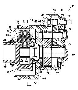
Next, the detailed structure of the gear box 14 of the
wind turbine generator 1 will be described. FIG. 3 is a
sectional view showing an example of the gear box 14. FIG.
4 is a sectional view along lines I-I of Fig.36. FIG. 5 is
an enlarged view showing around the self-aligning roller
bearing (planet bearing) of the gear box 14 shown in Fig. 3.
[0030]
As shown in Fig. 3, the gear box 14 includes a
planetary gear type speed increasing mechanism 50 and a spur
gear type speed increasing mechanism 70, accommodated within
the casing 40. This gear box 14 increases rotation speed
input from the main shaft 12 of the rotor hub side and
transmits the speed increased rotation to the final outp..it
shaft 16.
[0031]
The planetary gear type speed increasing mechanism 50
of the gear box 14 includes, as shown in Figs.3 and 4, a
carrier 52, a plurality of planet pins 54 held to the
- 11 -
CA 02694124 2010-02-24
carrier 52, a plurality of self-aligning roller bearings 56
supported to the planet pins 54, respectively, a plurality
of planet gears 58 supported to the planet pin 54s via the
self-aligning roller bearings 56, respectively, and a ring
gear 60 and a sun gear 62 meshed with the planet gears 58.
[0032]
The carrier 52 is a supporting plate for supporting the
plurality of the planet pins 54 (three pins in this example),
and rotated integrally with the main shaft 12 of the rotor
head side so that the carrier 53 revolves the planet pins 54.
The main shaft 12 and the carrier 52 are supported rotatably
to the casing 40 via a bearing 42.
[0033]
The self-aligning roller bearing 56 performs a role as
a planet bearing for supporting rotatably the planet gear 58
to the planet pin 54, and includes a plurality of rows of
the rollers 56C (two rows in this example) provided between
an inner race 56A and an outer race 56B as shown in FIG.5.
[0034]
The planet pin 54 is fit into an inner race 56A of the
self-aligning roller bearing 56, and an outer race 56B of
the self-aligning roller bearing 56 is fit into the planet
gear 58. For example, the planet pin 54 is fixed to the
inner race 56A of the self-aligning roller bearing 56 with a
clearance fit, and the outer race 56B of the self-aligning
roller bearing 56 is fixed to the planet gear 58 with an
interference fit.
[0035]
12 -
CA 02694124 2010-02-24
In the self-aligning roller bearing 56, the center of
the track of the outer race 56B coincides with the center of
the bearing to exercise self-aligning characteristics. Thus,
the self-aligning roller bearing 56 is proper to experience
vibration or impact load, and thereby preferable to be used
as a planet bearing of the wind turbine generator that the
wind power acting to the blades continuously changes.
[0036]
It is possible to use a plurality of the self-aligning
roller bearings 56 arranged parallel with each other as
shown in Figs. 3 and 5, when being applied to a large-size
wind turbine generator. In such case, as illustrated in
FIG.5, it is preferable to provide the plurality of the
self-aligning roller bearings with keeping a distance from
each other, further to provide a oil inlet port 54A on the
planet pin 54 in a position between the adjacent self-
aligning roller bearings 56 for leading lubricating oil into
the pair of self-aligning roller bearings. Thus, the self-
aligning roller bearings 56 can be maintained in the
lubrication state.
[0037]
The planet gears 58 shown in Figs. 3 and 4 are
supported to the planet pins 54 via the self-aligning roller
bearing 56, respectively, and meshed with the ring gear 60
and a sun gear 62.
[0038]
As shown in Fig. 3, the ring gear 60 is provided on the
casing 40, and includes an inner teeth meshed with the
- 13 -
CA 02694124 2010-02-24
planet gears 58. On the other hand, the sun gear 62 is, as
shown in Fig. 4, provided to be surrounded by a plurality of
the planet gears 58. A planetary output shaft 64 is fitted
into the sun gear 62.
[0039]
In this planetary type speed increasing mechanism 50,
the planet pins 54 and the planet gears 58 supported on the
planet pins 54 are revolved around the sun gear 62 as a
center, when the carrier 52 is rotated with the main shaft
12. At the same time, each of the planet gears 58 is
rotated around each of the planet pins 54 as a center via
each of the self-aligning roller bearings 56 as a planet
bearing. Thus, the rotational speed input from the main
shaft 12 as an input shaft is increased and output to the
planetary output shaft 64. The speed increasing ratio of
the planetary type speed increasing mechanism 50 is defined
by each number of teeth of the planet gear 58, the ring gear
60 and the sun gear 62.
[0040]
The casing 40 includes, as shown in Fig. 3, an oil bath
41 provided below the planetary type speed increasing
mechanism 50, and lubrication oil is reserved in the oil
bath 41. Each of the planet gears 58 supported to the
planet pin 54 via the self-aligning roller bearing 54 is
soaked in the lubrication oil within the oil bath 41, when
each of the planet gears moves down by the revolution. Thus,
the self-aligning roller bearings 56 and the planet gears 58
can be maintained in the lubrication state.
- 14 -
CA 02694124 2010-02-24
[0041]
The spur gear type speed increasing mechanism 70 shown
in Fig. 3 is a gear box optionally provided in addition to
the planetary gear type speed increasing mechanism 50, and
increases the rotational speed of the planetary output shaft
64 and outputs to the final output shaft 16.
[0042]
The spur gear type speed increasing mechanism 70
includes, for example as shown in Fig. 3, two gear sets
comprising a gear set of a first spur gear 72 and a second
spur gear 74 meshed with each other, and a gear set of a
third spur gear 76 and a fourth spur gear 78 meshed with
each other. The first spur gear 72 is fixed to a first
rotational shaft 80 connected to the planetary output shaft
64, the second spur gear 74 and the third spur gear 76 are
fixed to a second rotational shaft 82, and the fourth spur
gear 78 is fixed to the final output shaft 16. The first
rotational shaft 80, the second rotational shaft 82 and the
final output shaft 16 are supported by a first bearing 44, a
second bearing 46 and a third bearing 48, respectively.
[0043]
In this spur gear type speed increasing mechanism 70,
the number of the teeth of the first spur gear 72 is set
larger than the number of the teeth of the second spur gear
74 so that the rotational speed of the first rotational
shaft 80 connected to the planetary output shaft 64 of the
planetary type speed increasing mechanism 50 side is
increased and transmitted to the second rotational shaft.
- 15 -
CA 02694124 2010-02-24
[0044]
According to the gear box 14 arranged as above, the
rotational speed input from the main shaft 12 of the rotor
hub side can be increased by the planetary type speed
increasing mechanism 50 and the spur gear type speed
increasing mechanism 70, and transmitted to the final output
shaft 16.
[0045]
The inventors of the present invention had come up with
their recognition that in the gear box 14 with the above
structure, the endurance time of the self-aligning roller
bearing 56 may become shorter due to the flaking in the gear
box 14 having a construction as mentioned above. As a
result of every research of the inventors, it was uncovered
by the inventors that the decline of the endurance time of
the bearings occurred was caused by changes of the load and
the moment transmitted to the self-aligning roller bearings
56 from the blades 8 of the wind turbine generator 1 via the
rotor head 6 and the main shaft 12 whereby the outer race
56B of the self-aligning roller bearing 56 comes out and
therefore the load acted on each row 56c of bearings becomes
imbalance with each other, thereby causing the flaking.
[0046]
FIG. 6 is a sectional view showing coming out of the
outer race 56B of the self-aligning roller bearing 56
causing the flaking. The self-aligning roller bearing 56
tends to come out outward (the direction with an arrow in
the figure) in the axial direction by the load and the
- 16 -
CA 02694124 2010-02-24
moment transmitted from the blades 8. The inner race 56A of
the self-aligning roller bearing 56 is restrained from
moving outward in the axial direction by the carrier 52. On
the other hand, the outer race 56B of the self-aligning
roller bearing 56 in not restrained from moving in such
direction, and therefore only the outer race 56B is come out.
Accordingly, the load is concentrated on the roller-row 56c
located inside which is a right side row in FIG,6, and
therefore the flaking of the self-aligning roller bearing 56
occurs.
[0047]
In consideration of above, in the present embodiment,
each of the planet gears 58 is fixed, as shown in Fig. 7, to
the outer race 56B of the self-aligning roller bearing 58
with an interference fit so that the end surface of the
planet gear 56B of the self-aligning roller bearing 56 is
located inner side of the end surface of the planet gear 58
(i.e., the distance d between the end surface of the outer
race 563 and the end surface of the planet gear 58 as shown
in Fig. 7 is set to satisfy the inequality d>0). Thus, the
end portion of the planet gear 58 is deformed by the
interference fit to work as a lid to prevent the outer race
56B of the self-aligning roller bearings 56 from coming out
and to keep the load acted on each roller-row 56C in even,
and finally the decline of the endurance time of the self-
aligning roller bearings 56 caused by the flaking can be
suppressed.
[0048]
- 17 -
CA 02694124 2010-02-24
It is preferable that the distance d between the end
surface of the outer race 56B and the end surface of the
planet gear 58 is as great as possible in the view of
preventing the shortening of the life time of the planet
bearing 56 (self-aligning roller bearing). However, if the
end surface of the outer race 563 is set too close to the
inner side of the end surface of the planet bearing 56,
there is a structural limitation that the oil inlet port 54A
for leading the lubrication oil into the pair of the planet
bearings 56 may be obstructed. Therefore, it is preferable
to set the above distance d in a range of 0mm<d5_ 10mm.
[049]
In the present invention, a manner of fixing the planet
gear 58 to the outer race 56B of the self-aligning roller
bearing 58 is not limited to a special fit and may adopt any
fitting manner such as a shrink fit, a cooling fit or a
press fit, etc. Above all, a shrink fit or a cooling fit is
preferable for the fitting manner of the planet gear 58 in
view point that damage of the self-aligning roller bearing
56 can be reduced more effectively, since a shrink fit or a
cooling fit is possible to set a large amount of the
interference so as to deform the end portion of the planet
gear with a larger amount of the deformation, and therefore
can prevent the outer race 56B of the self-aligning roller
bearing 56 from coming out more firmly and further reduce
the flaking of the self-aligning roller bearing 56
[0050]
As described above, according to the embodiment, the
- 18 -
CA 02694124 2010-02-24
planet gears 58 are fixed to each the outer race 56B of the
self-aligning roller bearings 58 with an interference fit so
that the end surface of each planet gear 56B of the self-
aligning roller bearings 56 is located inner side of the end
surface of each planet gears 58. Thus, the end portion of
each planet gears 58 is deformed by the interference fit to
work as a lid to prevent the outer race 56B of each self-
aligning roller bearings 56 from coming out and to keep the
load acted on each roller-row 56C in even, and finally
flaking of the self-aligning roller bearings 56 can be
reduced.
[0051]
Having described the embodiment above, the present
invention is not limited to the embodiment and may be
appropriately modified without departing from the spirit and
the scope of the invention.
[0052]
For example, in the above embodiment, the end portion
of the planet gear 58 is deformed by the interference fit so
that the outer race 56B of the self-aligning roller bearing
56 is prevented from coming out by deforming. It is
possible to provide a flange portion at the end portion of
the planet gear so as to prevent the outer race 56B from
coming out.
[0053]
FIG. 8(a) is a sectional view showing the planet gear
58 equipped with the flange portion, Figs. 8(b) and 8(c) are
enlarged views showing an example of structure of flange
- 19 -
CA 02694124 2010-02-24
portions, respectively. It should be noted that the
elements same as that of the above embodiment is denoted
with the same reference numeral as used in the above
embodiment.
[0054]
As shown in Fig. 8(a), a flange portion 90 for
preventing the outer race of the self-aligning roller
bearing 56 is provided in a position between the end surface
of the outer race 56B of the self-aligning roller bearing 56
and the end surface of the planet gear 58. According to
such arrangement, the flange portion 90 is provided in the
inner surface of the planet gear 58. Therefore, the outer
race 56B of the self-aligning roller bearing 56 can be
prevented more certainly from coming out, and thus the
flaking of the self-aligning roller bearing 56 can be
reduced.
[0055]
For example, it is possible to adopt as the flange
portion 90 a C-shaped snap ring fit into a groove 92
provided in the inner surface of the planet gear 58 as shown
in Fig. 8(b), or a ring member screwed with a female screw
94 provided in the inner surface of the planet gear 58 as
shown in Fig.8(c).
[0056]
In Fig.8(a) to Fig.8(c) illustrated the example of the
flange portion 90 being provided in a position between the
end surface of the outer race 56B of the self-aligning
roller bearing 56 and the end surface of the planet gear 58
- 20 -
CA 02694124 2010-02-24
and also in the inner surface of the end portion of the
planet gear 58. However, the location of the flange portion
90 should not be limited to this arrangement as long as the
flange portion 90 is arranged in a position which can
prevent the outer race 563 from coming out. For instance,
the flange portion 90 may be assembled to the end surface of
the planet gear 58 by any method such as fixing with screws.
By this, even if the end surface 56B of the self-aligning
roller bearing coincide with the end surface of the planet
gear 58, the flange portion can be fixed to the end surface
of the planet gear 58 so as to prevent the outer race 56B
from coming out.
[Example]
[0057]
The durability for the gear box 14 in the above embodiment
has been evaluated as shown in the below by the inventors of
the present invention, by measuring the time-dependent
change of the coming out amount of the outer race 56B of the
self-aligning roller bearing 56.
[0058]
[Example 1]
The gear box 14 of FIG.3 is assembled in such a manner
that the end surface of the outer race 563 of the self-
aligning roller bearing 56 is positioned inside 10 mm of the
end surface of the planet gear 58 (i.e., d = 10 mm in Fig.
7). The interference fit of the planet gear 58 against the
outer race 56B is performed in conditions that the amount of
the interference is equal to P6 (0.012 to 0.079).
- 21 -
CA 02694124 2010-02-24
[0059]
The load equal to torque with the average of 1.18 kNm
is input from the main shaft (input shaft) 12 to the gear
box 14 assembled as above. Then, after a predetermined time
period elapsed, the amount of coming out of the outer race
56B of the self-aligning roller bearing 56 was measured.
[0060]
[Comparative Example 1]
The condition for the assembly and the input load is
same as the above Sample 1 except that the end surface of
the outer race 56B of the self-aligning roller bearing 56
and the end surface of the planet gear 58 are located at the
same position (i.e., d=0 in FIG. 7). Then, after the
predetermined time period elapsed, the amount of coming out
of the outer race 56B of the self-aligning roller bearing 56
was measured.
[0061]
[Evaluation of the durability]
FIG. 9 is a graphic diagram showing the test result of
Sample 1 and Sample 2.
[0062]
Meanwhile, inventors have found through their research
that flaking of the self-aligning roller bearing 56 is
occurred when the amount of coming out of the outer race 56B
reached to around 400 pm.
[0063]
According to the fitting curve of the Example 1 and the
Comparative Example 1, a time period that the amount of
- 22 -
CA 02694124 2010-02-24
coming out of the outer race 56B reached about 400 um of the
Example 1 (TE) is estimated approximately 109 times of that
of the Comparative Example 1 (Tc) . While the acceptance
criterion is 1.3 x 10⁵ (hr) in the ordinal practical
products, the Example 1 (TE) satisfied this criterion,
however, the Comparative Example 1 did not satisfy this
criterion.
[0064]
As mentioned above, in the gear box 14 of the present
embodiment, each of the planet gears 58 is fixed to each
outer race 56B of the self-aligning roller bearings 58 with
an interference fit so that the end surface of each outer
race 56B of the self-aligning roller bearings 56 is
positioned inner side of the end surface of each planet
gears 58, and thereby the outer race 56B of the self-
aligning roller bearings 56 is prevented from coming out,
and finally the decline of the endurance timeof the self-
aligning roller bearings 56 caused by the flaking can be
suppressed.
- 23 -