Note: Descriptions are shown in the official language in which they were submitted.
CA 02694145 2014-04-25
79313-12
PIVOTING GROUND ANCHOR
BACKGROUND OF THE INVENTION
Field of the Invention
This invention relates to ground anchors, and more specifically to driven
pivoting ground anchors.
General Background
Ground anchors, or earth anchors, of the driven and pivoting or tilting type
are
well known and generally include a main body portion having a leading edge
adapted to
be driven into the ground, a trailing edge including an outtumed lip and a
cable or rod
or guide wire attachment point intermediate the leading and trailing edges
generally
positioned from about the midpoint of the overall length of the anchor or
towards the
trailing edge so that upon exertion of the force on the cable or attached rod
or guide
wire, after insertion of the anchor into the ground, the trailing edge's
outtumed lip will
bite into the earth, causing the anchor to rotate or pivot to a locked
position generally at
a right angle to the withdrawal force.
Widely currently used driven pivoting anchors of the type described are
available from the assignee of this application under its Duckbill trademark
and
generally employ a somewhat cylindrical main body portion having an attachment
point =
intermediate its ends and having at its forward end a plurality of forwardly
extending
guiding plane surfaces which terminate in chiseled edges. The cylindrical body
shaped
member, at its trailing end, has a bore extending into the body of the
cylindrical
member for receipt of a drive rod for driving the anchor into the earth and is
provided
with an outtumed lip on a side of the cylindrical body portion opposite the
side having
the cable or guide wire attachment point.
1
CA 02694145 2010-01-21
WO 2009/023108 PCT/US2008/009403
Such anchors are shown, for example, in U.S. Patents 4,044,513 and 4,096,673,
both of which are assigned to the assignee of this application. Improvements
of such
anchors are well known and include, for example, applicant's pending Design
Application No. 29/270,187 and U.S. Utility Application 11/803,138 filed
5/14/2007.
Other variants of such anchors are sold, for example, by Foresight Products,
LLC under trademarks Manta Ray and Stingray and employ extensive side
projecting
wings that extend backwardly and outwardly from the leading edges to a greater
or
lesser degree and provide greater resistance to withdrawal of the anchor after
the anchor
has been driven into the ground and rotated to the point where the wings lie
substantially normal to the tension direction of the cable.
While such anchors, both of the wingless, small-winged and large wing design,
have found successful utility in many applications, including use in
connection with
revetment and soil retaining mats. However, the chiseled or sharpened leading
edges
which facilitate penetration into the ground can, in certain instances, cause
damage to
certain types of soil retaining mats which are commonly used in turf
reinforcement and
ground stabilization. Such mats, often known as High Performance Turf
Reinforcement
Mat (HPTRM) of the type available under the mark Pyramat from Propex, Inc. or
of the
type shown, for example, in U.S. Patent 5,616,399 entitled "Geotextile Fabric
Woven or
a Honeycomb Weave Pattern and having a Cuspated Profile after Heating," may
consist
of individual strands essentially woven together and formed or fused to
provide the mat.
The strands are generally manufactured of plastics material. Other fabric-like
woven
mats utilizing similar or different materials are also known, as are non-woven
mats.
Where it is desired to anchor such mats to the underlying soil, the use of the
previously
known driven pivoting anchors can cause damage to the mat, particularly since
the
2
CA 02694145 2014-04-25
79313-12
chiseled or sharpened leading edges will have a tendency to cut through the
material Of
the mat, thereby weakening the mat.
It would therefore be an advance in the anchoring field to provide an anchor
suitable for use with such turf reinforcement mats which could be driven
through the
mat with a reduced likelihood of damage to the mat.
Summary of the Invention
An embodiment of the invention is provided by utilizing a driven
pivotal anchor where the leading end is provided with a curved or rounded non-
sharp
leading end and flattened guiding plane edges.
In an embodiment of the invention a plurality of ribs or guiding plane leading
edges extend forwardly of the generally cylindrical main body portion of the
anchor
with each edge being either blunt or rounded and with each edge converging to
a
common leading end which is generally rounded.
In an embodiment of the invention the leading edges projecting forward of the
generally radial cylindrical main body portion are circumferentially spaced
from one
another and formed as the outside surface of ribs or guiding planes with the
edges
formed blunted or rounded and which converge to a common leading front end,
the
leading front end being rounded.
In an embodiment of the invention the generally cylindrical body member has
four leading edges formed as orthogonal ribs or planes extending forwardly of
the
generally cylindrical body portion and tapering to a common leading end which
is
rounded generally in a partial spherical configuration.
According to an embodiment of the invention, there is provided a ground anchor
having
improved utility for use with mat structures having leading edge surfaces
having a
3
CA 02694145 2014-04-25
=
79313-12
reduced tendency to damage the mat during driving of the anchor through the
mat structure.
According to another embodiment of the invention, there is provided a driven
pivoting anchor having a rounded or ball-like leading end.
These and other embodiments will be apparent to those of ordinary skill in the
art from a description of the illustrated preferred embodiment, being
understood that this is
only one such embodiment of this invention and that many variations of shape
and dimension
are within the scope of this invention. Specifically the generally overall
shape of the anchor,
the shape of the main central body portion, the shape and extent of the side
wings and the
number of leading edges or ribs are all modifiable as is generally known to
those of ordinary
skill in the art and practice in differing commercially available embodiments
of driven
pivoting anchors.
According to another embodiment of the invention, there is provided in a
driven pivoting anchor of the type having a leading end to be driven into the
ground, an
intermediate main body portion and a trailing end adapted to receive a driving
instrument for
applying a longitudinal driving force to the anchor, the anchor having an
attachment point for
attaching a withdrawal member, the improvement of the leading end being
rounded.
According to another embodiment of the invention, there is provided a driven
pivoting anchor comprising a main body portion, a leading edge and a trailing
edge, with a
blind bore extending into the main body portion from the trailing edge, a
raised rib or section
on the main body portion having an attachment point for attachment of a
withdrawal member,
with a plurality of rib-like members extending from the main body member to
the leading
edge the leading edge comprising the a rounded surface and the rib members
having outer
edge surfaces converging to the leading edge, the outer edge surfaces being
generally blunted.
According to another embodiment of the invention, there is provided a method
of securing a stranded soil retention mat to the soil, which comprises the
steps of providing a
driven and pivoting anchor having a non-sharp, curved leading edge,
positioning the mat on
the surface of the soil to be retained, positioning the leading edge of the
anchor against the
4
CA 02694145 2014-04-25
79313-12
mat, driving the anchor into the mat spreading the strands of the mat apart,
continuing the
driving of the anchor to a predetermined depth in the soil with an attachment
member attached
to the anchor and extending through the mat to a point opposite the mat from
the driven
anchor, causing rotation of the anchor by pulling on the attachment member and
thereafter
securing the mat to the attachment member.
Brief Description of the Drawings
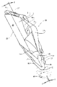
Figure 1 is a perspective view of the anchor of this invention.
Figure 2 is a cross sectional view of the anchor of this invention taken along
the lines 2-2 of Figure 1.
Figure 3 is a cross sectional view of the anchor taken along the lines 3-3 of
Figure 1.
Description of the Preferred Embodiment
Figure 1 illustrates a ground or earth anchor 10 of the type often referred to
as
a driven and rotating or pivoting anchor in that the anchor is driven into the
ground by force
and after having being driven to the desired depth, a cable or rod attachment
member attached
to the anchor is pulled in a direction to withdrawal the anchor from
4a
CA 02694145 2010-01-21
WO 2009/023108 PCT/US2008/009403
the ground. Because of the design of the anchor and the position of the
attachment of
the cable or pulling rod to the anchor, the pulling of the anchor by the
attachment
member causes the anchor to undergo a pivoting or rotation in the ground
towards a
final position in which the longitudinal axis of the anchor is positioned more
towards a
position normal to the pulling cable or rod.
Such anchors often include a main body section 11, which may be generally
cylindrically formed (other shapes are known in the art, including rectangular
and oval),
a leading edge 12, a trailing edge 13, a raised section 14 having means 2 for
attachment
of a cable, shackle, pivot bolt or the like, which may comprise or be attached
to the
withdrawing force member which causes the anchor to rotate or pivot from its
driven
position to its final locked position. As shown in Figure 1, oftentimes the
attachment
means 2 is merely an opening through a raised rib 16 on one side of the main
body
portion 11. The opening may receive a looped crimped cable end or a shackle
bracket
or the like. Alternative structures are well known such as where the rib-like
structure
includes attachment means for receipt of the end of a T-shaped rod or other
type of
swiveling device. An open bore 17 in the trailing edge extends into the main
body
portion 11 terminating in a blind end 18 which may, as shown in Figures 2 and
3, be flat
or which may be rounded or otherwise configured. A driving rod extends into
the bore
17 and is used to drive the anchor into the earth. The driving rod may simply
be
impacted by a hammer for smaller anchors or may be driven by a pneumatic or
hydraulic reciprocating power driver for larger anchors.
In the embodiment illustrated the main body portion is generally cylindrical
and
terminates at a leading end 11 a of the main body portion in a frustoconical
section 11 b
and four equally-distanced spaced ribs of which three, 15, 17, and 19 can be
seen in
Figure 1, the fourth being on the bottom opposite the rib 19. Each of the ribs
has an
5
CA 02694145 2010-01-21
WO 2009/023108 PCT/US2008/009403
outer edge surface 18 and the rib surfaces 18 converge towards the leading end
12. The
outer edges 18 may be flat or blunt as shown in Figure 1 or may be outwardly
curved
but preferably are not provided with a sharp edge. The ribs 15, 16, 17 may
have
different shapes. The ribs 15 and 17 extending back behind the frustoconical
portion
llb and converge into side wings 20 and 21, which also preferably have rounded
or
non-sharp outer edges 22. The rib 19 has its edge 18 extending back to the
leading end
of the generally conical section 11 a and blending into the top edge surface
14 of the
raised rib 16.
The four ribs, in this embodiment, converge together to a rounded nose 25 at
the
end 12. Although different shapes can be provided for the nose, a part
spherical or
partial ball shape is preferred, although a parabolic shape or some other
curvature is
acceptable, it being important that the leading end 12 not be provided with a
sharp edge.
By providing a rounded leading edge 12, the anchor is able to be driven
through the mat
with minimal damage to the stranding of the mat and, in fact, for smaller
anchors
without severing any of the strands of the mat as the ball-like nose 25 pushes
its way
between the strands and non-sharp, rounded or blunt edges 18 force the strands
apart as
the main body portion of the anchor begins to pierce through the mat.
The side 31 of the anchor opposite the raised rib 16 is provided at its
trailing
edge 32 with an outturned lip 33 to facilitate pivoting during drawback, as is
well
known in the art.
In use the mat schematically shown at 60 is placed in position on the surface
to
be retained or secured and the ball-like nose of the anchor is placed against
the mat
surface and is then begun to be driven through the mat. As the ball-like nose,
or
rounded nose, enters the structure of the mat it will cause the strands of the
mat to be
pushed aside. As the anchor is driven further into the mat, the degree by
which the
6
CA 02694145 2010-01-21
WO 2009/023108 PCT/US2008/009403
strands are pushed aside will increase to allow the anchor to pass through the
mat. In
many instances utilizing normally stranded mats and standard smaller sized
anchors
equipped with the rounded or ball-like nose leading edge, the entire anchor
can be
pushed through the mat without breaking the strands of the mat. In other
instances
when slightly larger anchors are used one or more of the strands may be
stretched
beyond its limit and separate, but damage to the mat is minimal compared to
the use of
sharper or chiseled or leading edges or sharper edges extending backwardly
from a
leading point. While the use of blunted, rounded non-sharpened nose portions
and
leading side edges on the ribs and along the body may increase the resistance
to driving
of the anchor into the ground, when such anchors are used for soil erosion or
soil
stabilization, they are most often used in connection with looser or less
resistant soil
conditions such that the disadvantage, which may rise from an increase in
resistance to
driving in comparison to chiseled edged or sharpened edged anchors is
minimized.
It will therefore be understood from the above that this invention improve
upon
the prior art driven pivoting anchors by providing an intentionally rounded
non-sharp
leading nose or leading end which can be pushed through a woven or non-woven
retaining mat with minimal damage to the mat.
Persons of ordinary skill in the art will understand that this invention may
be
practiced in embodiments other than that illustrated. It is not intended that
this
invention be limited to the particular anchor shape shown.
7