Note: Descriptions are shown in the official language in which they were submitted.
CA 02694399 2010-02-22
PLANT-CONTROLLED ATMOMETER FOR MEASURING CROP
EVAPOTRANSPIRATION
FIELD OF THE INVENTION
The present invention relates to an improved atmometer which is
particularly suited for measuring crop evapotranspiration, and more
particularly relates
to an atmometer which is responsive to soil moisture conditions.
BACKGROUND
Accurate evapotranspiration (ET) data is essential for determining the
depth of water to be applied through irrigation systems. At present, data from
weather stations are used in empirical equations to predict evapotranspiration
which is not site/crop specific and is prone to large errors. Alternatively,
pan
evaporation measurements and evaporation from porous plates (atmometers) have
been used to measure the depth of evaporation and relate this measurement to
ET
using crop coefficients. However, plant evapotranspiration is controlled not
only by
weather conditions but also by soil water content. The atmometer, pan
evaporation,
and the weather-data based methods of predicting ET are not affected by soil
water
content and therefore do not take into account the plant response to soil
moisture
deficit as shown in the constant rate in Fig 1. This error might lead to an
over
application of irrigation water.
Atmometers and pan evaporation meters have been used for over 50
years as a method to measure evaporation rate as affected by weather
conditions. As
noted above, this evaporation rate is multiplied by a crop coefficient to
estimate
evapotranspiration from a crop. When the soil is wet, the crops evapotranspire
at the
maximum rate just like the evaporation from an atmometer or a pan evaporation
meter characterized by the weather limiting phase as shown in Figure 1.
However,
CA 02694399 2010-02-22
2
when the soil becomes dry, the plants find it difficult to draw water from the
soil
leading to a decrease in evapotranspiration due to increased stomata!
resistance.
Consequently, the plants tend to lower their ET rate by stomata! closure
(wilting) to a rate to match decreased flow of water towards the roots through
the dry
soil within the root zone. This phenomenon is shown in figure 1 as a declining
part of
the graph located within the soil-limiting phase. However, the traditional
atmometer or
the pan evaporation meter is unresponsive to soil water content. Therefore,
any
estimation of ET based on evaporation from conventional atmometers will lead
to an
over-estimation of the ET. This will lead to over-application of irrigation
water for
crops, gardens, or golf courses.
SUMMARY OF THE INVENTION
According to one aspect of the invention there is provided a method of
estimating crop evapotranspiration during a given time period, the method
comprising:
providing an atmometer comprising a porous evaporator member, a
reservoir for supplying water, maintained at constant head, to the porous
evaporator
member, and a suction tube for communicating water from the reservoir to the
porous
evaporator member;
measuring a moisture characteristic of the soil;
controllably varying a rate of evaporation of the water through the
porous evaporator member responsive to the measured moisture characteristic of
the
soil; and
determining an amount of water loss in the reservoir during the given
time period.
The method may include varying the rate of evaporation by varying a
resistance of the flow of water along the suction tube from the reservoir to
the porous
CA 02694399 2010-02-22
3
evaporator member. In a preferred embodiment, varying a resistance to the flow
of
water through the suction tube may be accomplished by varying an amount of
porous
medium the water must flow through.
Alternatively, the method may include varying the rate of evaporation of
the water through the porous evaporator member by varying characteristics of
the
porous evaporator member.
The measured moisture characteristic of the soil may comprise a
moisture content of the soil, a degree of soil suction or a measured soil
resistance
related to moisture content in the soil.
The moisture characteristic may be measured by burying a moisture
sensor in a plant root zone of a crop.
In some embodiments, there may be provided a plurality of atmometers
in a crop, each associated with a respective region of the crop such that crop
evapotranspiration may be estimated according to region.
In a preferred embodiment, the amount of water loss of the reservoir
may be determined by comparing weight of the reservoir before and after the
given
the time period.
According to another aspect of the present invention there is provided
an atmometer device comprising:
a porous evaporator member;
a reservoir arranged for supplying water to the porous evaporator
member;
a suction tube arranged for communicating water from the reservoir to
the porous evaporator member;
a sensor arranged for measuring a moisture characteristic of soil
CA 02694399 2010-02-22
4
associated with a crop;
a mechanism arranged for controllably varying a rate of evaporation of
the water through the porous evaporator member responsive to the moisture
characteristic measured by the sensor; and
an indicator arranged to indicate water loss in the reservoir.
In the preferred embodiment, the mechanism is arranged to vary a
resistance to water flow communicating through the suction tube from the
reservoir to
the porous evaporator member by varying an amount of porous medium that the
water must flow through from the reservoir to the porous evaporator member. In
this
instance, the mechanism may further comprise a plurality of valves associated
with
respective passages through the porous medium, so that a controller may
operate the
valves to controllably vary the rate of evaporation of the water through the
porous
member.
When there is provided a water level sensor in the reservoir arranged to
determine water loss in the reservoir, a transmitter may be arranged to
transmit the
determined water loss from the reservoir to a remote recording station.
Preferably the
recording station is arranged to communicate with a plurality atmometer
devices of
like configuration associated with different regions of the crop.
The plant-controlled atmometer device described herein overcomes
the disconnect of the prior art by linking the atmometer response to soil
water
deficit. In this invention, the rate of evaporation from the porous plate of
the
atmometer is controlled by a mechanism connected to a sensor buried within the
plant rootzone. If the soil is wet, the plants will evapotranspire at the
maximum rate
similar to the evaporation rate though the atmometer or a pan evaporation
meter.
However, as the soil becomes dry the plants will evapotranspire at a lower
rate.
CA 02694399 2010-02-22
Similarly, the sensor buried within the rootzone will activate the mechanism
to
decrease the evaporation rate through the atmometer. Thus the evaporation
measured by the plant-controlled atmometer will closely mimic the ET of the
plant.
The change in volume of water within the plant-controlled atmometer can be
directly
5 read by the irrigator or the data can be transmitted via telemetry to a
remote location
where the irrigation system control is housed. Compared to existing methods,
the
plant-controlled atmometers are relatively inexpensive and multiple units can
be
used in a field to more accurately measure ET.
In a preferred embodiment, the soil water sensor buried within the
rootzone of the crop will monitor the capillary pressure/soil water content.
This data is
transmitted to a mechanism within the atmometer that will directly control the
evaporation rate through the porous membrane. As noted above, if the soil is
dry, it
will increase the resistance to evaporation from the atmometer. The larger the
soil
water deficit, the lower the evaporation rate from the atmometer. Therefore,
the plant-
controlled atmometer closely mimics the evapotranspiration of the plants by
linking
the rate of evaporation from the plant-controlled atmometer to capillary
pressure/soil
water content within the root zone of the crop. The plant-controlled atmometer
can
conserve valuable water by accurately predicting the depth of irrigation.
Some embodiments of the invention will now be described in
conjunction with the accompanying drawings in which: 11
BRIEF DESCRIPTION OF THE DRAWINGS
Figure 1 is a graph illustrating evapotranspiration from plants and a plant
controlled atmometer compared to a conventional atmometer and pan evaporation
meter measurements as a function of time.
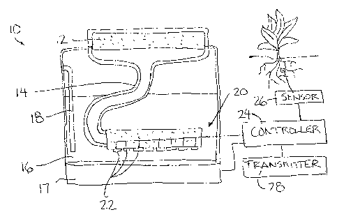
Figure 2 is a schematic representation of a preferred embodiment of the
=
CA 02694399 2010-02-22
6
atmometer device according to the present invention.
Figure 3 is a graphical representation of soil water content measured at
various soil depths subsequent to irrigation and rain.
Figure 4 is a graphical representation of stem flow rate from cotton
before and after irrigation clearly showing the plant response to soil water
deficit.
Figure 5 is a graphical representation of evaporation from a water table
as a function of the suction prevailing at the soil surface for various water
table
depths.
Figure 6 is a graphical representation of a relationship between
evaporation rate from different soil textures and evaporation rate from a free
water
surface.
Figure 7A is a graphical representation of evaporation rate versus time
under different evaporativities.
Figure 7B is a graphical representation of the relation of relative
evaporation rate versus time indicating three stages of the drying process.
DETAILED DESCRIPTION
The general purpose of this invention is to accurately measure the crop
evapotranspiration so that the depth of next irrigation can be determined. At
present,
there are no accurate methods available that are simple enough for ordinary
farmers
to use. The existing prior art atmometer is not responsive to soil moisture
conditions
and therefore does not reflect what is truly happening in the field.
Referring to the accompanying figures there is illustrated an atmometer
device generally indicated by reference numeral 10. The device 10 is
particularly
suited for estimating crop evapotranspiration in a manner which is responsive
to soil
moisture conditions.
CA 02694399 2010-02-22
7
The device comprises an evaporator member formed of a porous plate
which is wetted and arranged to permit evaporation from an upper surface
thereof.
The upper surface may include a suitable covering thereon to prevent rain
seepage
into the porous plate and to also simulate the evaporation from a crop canopy.
A suction tube 14 communicates with a bottom surface of the evaporator
member 12 to supply the evaporator member with water from a suitable reservoir
16.
The reservoir includes an indicator associated therewith for indicating to a
user a
content of water within the reservoir so that the user can determine an amount
of
water loss in the reservoir. When visually gauging the water loss in the
reservoir, a tall
narrow shape of reservoir is desirable for increased visual accuracy of the
varying
water levels in the reservoir. Alternatively, an inclined water level tube or
sight gauge
can be attached to the reservoir to increase the visual accuracy of the water
level
measurement by lengthening the sight gauge within a given height restriction
of the
reservoir. In the illustrated embodiment, the reservoir includes a suitable
weight
sensor 17 which is arranged to calculate a difference in weight indicative of
a water
loss in the reservoir and accordingly the reservoir can be of any shape
without
affecting the indication of water loss in the reservoir. The water loss is
typically
determined over a given period of time for example the period between
irrigations of a
crop which may be in the range of 10-14 days as an example.
The reservoir 16 is sealed with respect to the suction tube 14
communicating between the reservoir and the evaporator member except for an
air
passage 18 communicating through the wall of the reservoir between a top end
above
an uppermost water level in the reservoir externally of the reservoir and a
bottom end
at a fixed elevation terminating within the interior of the reservoir so as to
remain
submerged near a bottom end of the reservoir. The air passage ensures that
suction
CA 02694399 2010-02-22
8
of water in the suction tube on the bottom side of the evaporator member 12
remains
constant despite varying water levels in the sealed reservoir, thereby,
maintaining a
constant head which is not affected by the water level within the reservoir.
The atmometer device 10 includes a suitable mechanism 20 which is
arranged to vary the rate of evaporation of water through the porous
evaporator in a
controlled manner responsive to moisture conditions of the soil monitored by
the
atmometer device. In the illustrated embodiment, the mechanism 20 comprises a
porous medium, for example clay or other suitable materials which allow a
restricted
flow of water therethrough. The porous medium communicates between a plurality
of
different inlets 22 in communication adjacent a bottom end of the reservoir
and the
suction tube in communication with the evaporator member 12. Each of the
inlets 22
includes a respective valve associated therewith for defining a respective
flow path
through the porous medium from the fluid in the surrounding reservoir to the
inlet of
the suction tube in which each path has a varying resistance to the flow of -
water from
the reservoir through the suction tube to the evaporator member 12.
A controller 24 is provided which operates the valves on the inlets 22 of
the porous medium to vary the amount of porous medium that the water must flow
through the suction tube to the evaporator member 12. By increasing the amount
of
porous medium the water must flow through, resistance to the flow through the
suction tube is increased which in turn increases the amount of suction on the
bottom
face of the porous plate to effectively lower the rate of evaporation of water
from the
upper surface of the plate.
In further embodiments the rate of evaporation may be controllably
varied by varying a height of the communication of the air passage 18 with the
fluid in
the reservoir. In yet a further arrangement, evaporation from the evaporator
member
CA 02694399 2010-02-22
9
12 may be varied by varying a characteristic of the plate, for example an
exposed
surface area of the plate.
In either instance, the rate of evaporation is varied according to a
moisture condition of the soil measured by a suitable sensor 26 which is
arranged to
be buried in the root zone of a crop being monitored. The sensor is arranged
to
measure a moisture characteristic of the soil for example a moisture content
of the
soil or soil suction in the form of capillary pressure in the soil. A
preferred type of
moisture sensor 26 is a commercially available moisture meter which uses a
gypsum
block supported in the soil. The sensor 26 may further be configured for
measuring
an electrical resistance of the soil which is related to the moisture content.
In either instance, the controller 24 of the present invention is arranged
to increase the resistance to the flow of water through the suction tube when
the
sensor 26 determines that the soil is in a drier condition where
evapotranspiration
from the crop is reduced. Alternatively, when the sensor 26 determines wetter
conditions of the soil resulting in an optimal increased evapotranspiration of
the crop,
resistance of the flow through the suction tube to the evaporator member 12 is
reduced so that the evaporation from the evaporation member 12 most closely
represents the actual evapotranspiration of the crop being monitored.
In some embodiments a plurality of atmometer devices of like
configuration are located in various regions of a given crop for determining
different
water losses of the soil as a result of evapotranspiration in different
regions of the
crop. Alternatively, a plurality of root zone sensors may be provided within
one region
of a crop for collectively determining the moisture characteristics of the
region to
which a single atmometer device reacts. In either instance when providing a
plurality
of sensors or atmometer devices distributed about a crop, the water loss of
the
CA 02694399 2010-02-22
reservoir is preferably determined electronically by a suitable sensor 17 for
communication by the controller 24 to a transmitter 28 which relays the water
loss
information to a common recording station remote from the sensors of the
atmometers.
5 Figure 3 shows the soil water content at three different depths on
two consecutive days before and after irrigation/rain in a Cotton crop. The ET
represented by average stem flow has increased from 47 g/h to 79 g/h due to an
increase in soil water content (volumetric basis) from 0.15 to 0.33 at a depth
of
0.3 m below the ground surface. This is clear indication that the plant ET
rate is
10 highly responsive to soil water content towards the later days of the
irrigation
interval.
The conventional Atmometer and the Pan Evaporation Method do
not account for this plant response to soil moisture status. Yet, millions of
units
are used around the world to schedule irrigation, resulting in over-estimation
of
the plant water use by over 70% i.e. 79 g/h instead of 47 g/h.
The proposed plant-controlled atmometer will closely mimic the plant
water use, leading to a large reduction in irrigation water use that will
otherwise
be wasted as deep percolation.
As described herein, the present invention relates to the creation of the
link between the evaporation rates from the atmometer to the soil water status
within
the root zone. None of the traditional methods have this link. The main
advantage of
this invention is it enables us to accurately measure ET by mimicking crop
evapotranspiration.
Two variations of the atmometer device are contemplated. The first is a
low-cost plant-controlled atmometer that can be directly read by the farmer on
a daily,
CA 02694399 2016-02-23
11
weekly, or per irrigation cycle basis to make irrigation decision. The second
product
will have the capability to transmit the ET data directly via telemetry to
another
location.
The existing atmometers are not accurate in predicting ET because the
correlation is about 70% at best. That is 30% error in estimation of ET and
30%
waste of water! There are no current solutions to the problem of disconnect
between
the conventional atmometer and soil water status. The plant-controlled
atmometer
will more accurately estimate of ET. The plant-controlled atmometer is
inexpensive
and simple for the farmer to use.
The plant-controlled atmometer has the potential to be used world-wide
because of the scarcity of water for irrigation. A 30 % savings in water will
translate to
30% increase in irrigated agriculture. Many companies sell weather stations
for
predicting ET and our product will be in direct competition to the weather
stations
used in ET prediction for irrigation scheduling. Weather station based methods
suffer
from the same draw back i.e. soil water status is ignored. The low-cost non-
recording
version of the product is simple enough for use by farmers in developing
countries.
Irrigation companies, Irrigators, Golf courses, farmers, and people with
large lawns are some of the potential end-users. It can be used as research
tools by
hydrologists, and foresters studying water balance in a watershed.
Since various modifications can be made in my invention as herein
above described, and many apparently widely different embodiments of same
made,
it is intended that all matter contained in the accompanying specification
shall be
interpreted as illustrative only and not in a limiting sense.