Note: Descriptions are shown in the official language in which they were submitted.
CA 02694438 2014-07-08
SYSTEM AND METHOD FOR CONTROLLING POWER BASED ON
IMPEDANCE DETECTION, SUCH AS CONTROLLING POWER TO TISSUE
TREATMENT DEVICES
TECHNICAL FIELD
[0002] The present application relates generally to medical treatment
devices, such as
devices that treat lung diseases by applying energy to airways to reduce the
resistance to
airflow in the airways.
BACKGROUND
[0003] Asthma is a disease that makes it difficult to breathe and in many
cases can be
debilitating. Asthma is generally manifested by (i) bronchoconstriction, (ii)
excessive mucus
production, and/or (iii) inflammation and swelling of airways that cause
widespread but
variable airflow obstructions. Asthma can be a chronic disorder often
characterized by
persistent airway inflammation, but asthma can be further characterized by
acute episodes of
additional airway narrowing via contraction of hyper-responsive airway smooth
muscle
tissue.
[0004] Conventional pharmacological approaches for managing asthma include:
(i)
administering anti-inflammatories and long-acting bronchodilators for long-
term control,
and/or (ii) administering short-acting bronchodilators for management of acute
episodes.
Both of these pharmacological approaches generally require repeated use of the
prescribed
drugs at regular intervals throughout long periods of time. However, high
doses of
corticosteroid anti-inflammatory drugs can have serious side effects that
require careful
management, and some patients are resistant to steroid treatment even at high
doses. As such,
-1-
CA 02694438 2014-07-08
effective patient compliance with pharmacologic management and avoiding
stimuli that
triggers asthma are common barriers to successfully managing asthma.
[0005] Asthmatx, Inc. has developed new asthma treatments that involve
applying
energy to alter properties of the smooth muscle tissue or other tissue (e.g.,
nerves, mucus
glands, epithelium, blood vessels, etc.) of airways in a lung of a patient.
Several
embodiments of methods and apparatus related to such treatments are disclosed
in
commonly-assigned U.S. patent Nos. 6,411,852, 6,634,363, 7,027,869, and
7,104,987; and
U.S. Published Application Nos. US2005/0010270 and US2006/0247746.
[0006] Many embodiments of the foregoing asthma treatments that apply
energy to
tissue of the airways use catheters that can be passed (e.g., navigated)
through the tortuous
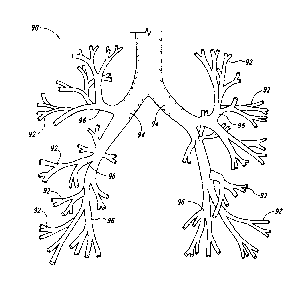
passageways defined by the lung airways. Figure 1, for example, illustrates a
bronchial tree
90 in which the various bronchioles 92 decrease in size and have many branches
96 as they
extend from the right and left bronchi 94. Accordingly, the treatment devices
should be
configured to treat airways of varying sizes as well as function properly when
repeatedly
deployed after navigating through the tortuous anatomy.
[0007] It is also desirable to control the amount and rate of energy
delivered to the
treatment site. For example, the energy delivery devices for delivering radio
frequency (RF)
energy to tissue in the lung airways disclosed in the commonly-assigned
patents and
applications incorporated by reference above have been controlled by measuring
the
temperature of one of the electrodes during energy delivery. Other types of
treatment devices
that deliver RF energy for other applications outside of the lung airways,
such as ablation and
cauterization devices, have controlled the delivery of energy to cardiac and
vasculature tissue
based on measuring factors other than temperature. For example, ablation and
cauterization
devices have monitored impedance during a procedure and terminated energy
deliver when a
sharp increase in the impedance is measured. This sharp increase may correlate
with a
desired end result, such as tissue desiccation or protein denaturation. As
such, existing
ablation and cauterization systems may terminate energy delivery based on a
direct
relationship between an increase in impedance and an increase in temperature.
-2-
CA 02694438 2010-01-25
WO 2009/015278 PCT/US2008/071037
BRIEF DESCRIPTION OF THE DRAWlNGS
[0008] The following drawings should be read with reference to the detailed
description. Like numbers in different drawings refer to like elements. The
drawings, which
are not necessarily to scale, illustratively depict embodiments of the
disclosure and are not
intended to limit the scope of the disclosure.
[0009] Figure 1 is an illustration of the airways within a human lung.
[0010] Figure 2A is a schematic view illustrating a system for delivery of
energy
according to some embodiments.
[0011] Figures 2B and 2C are side views in partial cross-section
illustrating a portion of
a treatment device for supplying energy to tissue within the body.
[0012] Figure 3 is a flow diagram illustrating a routine for controlling
the power during
treatment using impedance measurements.
[0013] Figure 4 is a block diagram illustrating a system for controlling
the power during
treatment using impedance measurements.
[0014] Figures 5 is a schematic view illustrating an example electrode
configuration of
a treatment device in a passageway.
[0015] Figure 6 is a block diagram illustrating an example proportional
integral
derivative (PD) algorithm for use in calculating applied power.
[0016] Figure 7 is a chart illustrating a function of temperature and
impedance versus
time during treatment.
[0017] Figure 8 is a chart further illustrating a correlation between
temperature and
impedance in more detail.
DETAILED DESCRIPTION
Overview
[0018] Devices, systems, and methods for controlling the treatment of
internal tissue
using measured impedance of an energy delivery device and/or targeted tissue
are described.
In some examples, the system controls power to the energy delivery device
based on the
measured impedance. The system may determine a desired or set impedance level
related to
-3-
CA 02694438 2010-01-25
WO 2009/015278 PCT/US2008/071037
parameters of the treatment site and/or of the energy delivery device, measure
a current or
present impedance level during or prior to energy delivery to the treatment
site, and control
the power to maintain the temperature or other parameter of the treatment site
based on the
two impedances.
[0019] Several of the details set forth below are provided to describe the
following
examples and methods in a manner sufficient to enable a person skilled in the
relevant art to
practice, make and use them. Several of the details and advantages described
below,
however, may not be necessary to practice certain embodiments and methods of
the
technology. Additionally, the technology may include other examples and
methods that are
within the scope of the claims but are not described in detail.
[0020] The particular features, structures, routines, steps, or
characteristics may be
combined in any suitable manner in one or more examples of the technology. The
headings
provided herein are for convenience only and are not intended to limit or
interpret the scope
or meaning of the claimed technology.
[0021] In some examples, the system provides closed loop power control of
energy
delivery devices based on impedance feedback. By monitoring impedance at low
non-
ablative temperatures (e.g., temperatures below tissue desiccation or protein
denaturation
temperatures), several embodiments of the system may enable the simplification
of devices
used in the treatment systems and/or may result in more stable or consistent
treatment
delivery. At short treatment times and/or low power and temperature levels,
impedance may
inversely correlate to temperature because electrical conductivity of the
tissue increases
because of increased mobility of charge carriers within the tissue. The
impedance
accordingly decreases with increases in temperature in such circumstances
(impedance =
1/conductivity). This inverse correlation of temperature and impedance enables
the system to
(a) measure the impedance of the system using electrodes of an energy delivery
device that
provide energy to target tissue in order to receive feedback about the
temperature or other
parameters of the target tissue, and (b) adjust power to the energy delivery
device accordingly.
[0022] In some cases, for example, measuring impedance may eliminate the
need to
measure temperature during the delivery of radio frequency or other energy to
tissue, and thus
several embodiments of the system may utilize catheters without thermocouples
or other
temperature measurement components. As a result, several embodiments of
treatment
devices may be small, simple, and relatively less expensive to manufacture.
Additionally,
-4-
CA 02694438 2010-01-25
WO 2009/015278 PCT/US2008/071037
controlling power by measuring impedance may enable the system to more
accurately or
holistically assess the state of the tissue around the passageway because
measuring impedance
may result in less temperature variability in the tissue versus measuring
temperature at only a
single location in the passageway. This may result in a more accurate
treatment and/or in
more consistent energy delivery between applications because impedance
monitoring may be
less susceptible to variation than temperature monitoring within a treatment
location or
between treatment locations.
Embodiments of a Treatment System
[0023] Specific details of several embodiments of treatment systems and
methods for
delivering energy to passageways in a patient are described. Although many of
the
embodiments are described below with respect to delivering RF energy to
airways in a lung of
a patient to treat asthma, other embodiments that deliver other energy
modalities to lung
airways or other types of passageways or tissues (e.g., blood vessel, skin,
etc.) for treating
other indications may be within the scope of the invention. For example, other
types of
energy modalities can include thermal (resistive and/or infrared), microwave,
laser, ultrasonic
(e.g., HIFU), cryo-ablation, radiation, or other modalities. Moreover, several
other
embodiments of the invention can have different configurations, components, or
procedures
than those described in this section.
[0024] Figure 2A is a schematic view illustrating a system 100 for
delivering energy to
passageways in a patient having a power/control unit 110 and an energy
delivery device 120
in accordance with an embodiment of the disclosure. The power/control unit 110
can include
an energy generator 111 (e.g., power supply), a controller 112 having a
processor 113, and a
user interface 114. The energy generator 111 and controller 112 can provide RF
energy to the
energy delivery device 120, but in other embodiments the energy generator 111
and controller
112 can provide other energy modalities. The controller 112 can contain safety
algorithms
and other control algorithms that control (i) the power output to the energy
delivery device
120 and (ii) the indicators 118, 119, 121, 122 of the user interface 114. The
power/control
unit 110 can further include one or more connections 123, 124, 125 for an
optional return
electrode 115 for monopolar RF configurations, an optional switch 116 (e.g.,
an actuation
pedal) for directing the controller 112 to cause the energy generator 111 to
provide energy,
and a conductive line 117 and connector 126 coupled to the energy delivery
device 120. It
-5-
CA 02694438 2014-07-08
will be appreciated that the depictions herein are for illustrative purposes
only and do not
necessarily reflect the actual shape, size, or dimensions of the system or
device.
[0025] The
energy delivery device 120 is an example of a treatment device for treating
asthma or other indications associated with passageways in a human. The
embodiment of the
energy delivery device 120 illustrated in Figure 2A includes an elongated body
130 with a
distal portion 132 and a proximal portion 134, an energy delivery unit 140 at
the distal portion
132, and a handle 150 at the proximal portion 134. The length of the elongated
body 130
should be sufficient to access the target tissue in airways of the lung or
other passageways
targeted for treatment. For example, the length of the elongated body 130 can
be from
approximately 0.5-8 feet to allow passage through a bronchoscope and reach
targeted airways
deep within the lungs. The elongated body 130 can also be configured to treat
airways as
small as 3 mm in diameter, but the elongated body 130 is not limited to
treating airways of
any particular size such that airways smaller or larger than 3 mm may be
treated. Typically,
the delivery unit 140 expands/contracts to variable sizes to treat airways
between 3-10 mm.
[0026] Several
embodiments of the elongated body 130 are flexible catheters
configured to slide through the working lumen of an access device (e.g.,
bronchoscope). The
elongated body 130 can also include a plurality of markers 136 at the distal
section 132 to
position the energy delivery unit 140 relative to an access device (not shown
in Figure 2A)
and a proximal marker(s) 127 so as to assist in expedient positioning of the
energy delivery
unit 140 out of the distal end of the access device. Specific embodiments of
elongated bodies
with markers suitable for use in the system 100 as described in U.S. Patent
No. 8,235,983 and
in U.S. Patent No. 7,931,647 and in U.S. Published Application No.
US2007/0106292A1.
[0027] The
energy delivery unit 140 can have at least one energy delivery element, such
as an electrode 142, configured to deliver energy to the tissue of an airway
or other
passageway in the patient. Figure 2B is a partial cross-sectional view showing
an
embodiment of the energy delivery unit 140 in greater detail. In this
embodiment, the energy
delivery unit 140 includes four electrodes 142, a proximal sleeve 138a and a
proximal
alignment extrusion or retainer 144a fixed to the elongated body 130 and
attached to the
proximal ends of the electrodes 142, and a distal sleeve 138b and a distal
alignment extrusion
or retainer 144b attached to the distal ends of the electrodes 142. The energy
delivery device
120 can also include a wire 146 attached to the distal retainer 144b at the
distal sleeve 138b
-6-
CA 02694438 2014-07-08
and configured to move through a lumen 147 of the elongated body 130 and the
proximal
retainer 144a.
[0028] The example of the energy delivery unit 140 illustrated in Figure 2B
is a
"basket-type" configuration in which the electrodes 142 move outwardly (arrows
0) as the
wire 146 moves proximally (arrow P) relative to the elongated body 130. The
electrodes 142
can move inwardly (arrows I) by releasing the wire 146 such that a spring or
other resilient
element in the handle 150, and/or the spring force of the electrodes 142,
drives the wire 146
distally. The outward/inward movement of the electrodes 142 is useful when the
device is
operated intralumenally or in airways in the lungs because the energy delivery
unit 140 can be
advanced through a working lumen 181 of an access device 180 while the
electrodes 142 are
in a low-profile configuration, and then the electrodes 142 can repeatedly be
moved
outwardly according to the varying sizes of the passageways. Visualization of
this may be
facilitated by an imaging lumen 128 and/or light optical fiber lumens 129 of
the access device
180 (or optical chip(s) or fiber(s) mounted at the distal end of the access
device). In this
illustration, the pull wire 146 may also comprise a conductive wire between
the electrodes
142 and the energy supply 111.
[0029] Figure 2C is an exploded view illustrating a portion of one
electrode 142 in
greater detail. The electrode 142 has an outer insulating material or coating
143 at proximal
and distal ends so as to define a non-insulated, active central portion 145 of
the electrode 142
which delivers controlled energy to the tissue walls. Specific embodiments of
suitable
electrode configurations are disclosed in U.S. Publication No. US2007/0118184.
Further
embodiments of suitable electrodes and retainers for preventing electrode
inversions and
limiting basket expansions are disclosed in U.S. Publication No.
US2007/0106292. The
system 100 may deliver energy to target sites via the energy delivery device
120 in a variety
of treatment patterns. Further details with respect to other designs and types
of treatment
devices, examples of energy, and/or examples of treatment patterns may be
found in
commonly-assigned U.S. Patent No. 6,411,852.
[0030] Referring back to Figure 2A, the illustrated example of the handle
150 is
configured so that a single operator can hold an access device (e.g., a
bronchoscope) in one
hand (e.g., a first hand) and use the other hand (e.g., a second hand) to (i)
advance the
elongated body 130 through a working lumen of the access device until the
energy delivery
unit 140 projects beyond the distal end of the access device and is positioned
at a desired
-7-
CA 02694438 2010-01-25
WO 2009/015278 PCT/US2008/071037
target site and (ii) pull the wire 146 (Figure 2B) to move the electrodes 142
outwardly until
they contact the sidewall of an airway passage while the catheter is held in
place relative to
the access device with the same second hand. The same operator can also
operate the switch
116 of the power/control unit 110 such that the entire procedure can be
performed by a single
person.
[0031] In one embodiment, the handle 150 has a first portion 151 and a
second portion
152 rotatably coupled to the first portion 151 by a joint 153. The first
portion 151 and/or the
second portion 152 are one example of an actuator for manipulating the
electrodes 142. The
first and second portions 151-152 can be configured to form a grip 154 and a
head 156
located at an upper portion of the grip 154. The head 156, for example, can
project outwardly
from the grip such that a portion of the grip 154 is narrower than the head
156. In the specific
embodiment illustrated in Figure 2A, the first portion 151 has a first curved
surface 161 with
a first neck portion 163 and a first collar portion 165, and the second
portion 152 has a second
curved surface 162 with a second neck portion 164 and a second collar portion
166. The first
and second curved surfaces 161-162 can be configured such that they are
arranged to define a
hyperbolic-like shaped grip when viewed from a side elevation.
[0032] In several embodiments of the system, the controller 112 includes a
processor
that is generally configured to accept information from the system 100 and
system
components, and process the information according to various algorithms to
produce control
signals for controlling the energy generator. The processor may also accept
information from
the system and system components, process the information according to various
algorithms,
and produce information signals. The information signals may be directed to
the visual
indicators, a digital display or an audio tone generator of the user interface
to inform the user
of the system status, component status, procedure status, or any other useful
information that
is being monitored by the system. The processor of the controller 112 may be a
digital IC
processor, analog processor or any other suitable logic or control system that
carries out the
control algorithms.
[0033] Several embodiments of the system 100 shown in Figures 2A and 2B can
be
controlled by measuring the impedance before, during and/or after delivering
energy to the
tissue of the passages. The following discussion provides a brief, general
description of a
suitable environment in which the control of the system 100 may be
implemented. Although
not required, aspects of the system and various components (such as the
controller 112) are
-8-
CA 02694438 2010-01-25
WO 2009/015278 PCT/US2008/071037
described in the general context of computer-executable instructions, such as
routines
executed by a general-purpose computer (e.g., personal computer, laptop,
mobile device,
hand-held computer, etc.). Those skilled in the relevant art will appreciate
that the system
may be practiced with other communications, data processing, or computer
system
configurations, including Internet appliances, other handheld devices
(including personal
digital assistants (PDAs)), embedded computers, multi-processor systems,
microprocessor-
based or programmable consumer electronics, network PCs, mini-computers,
mainframe
computers, and the like. The terms "computer" and the like are generally used
interchangeably and refer to any of the above devices and systems, as well as
any data
processor. For example, an exemplary computing system may include a processor,
input
devices, data storage devices, such as hard disks or removable media, display
devices, and/or
output devices. Additionally, the system 100 may connect to various networked
environments
via a network connection or a wireless transceiver.
[0034] Aspects of the system may be embodied in a special purpose computer
or data
processor that is specifically programmed, configured, or constructed to
perform one or more
of the computer-executable instructions explained in detail herein. Aspects of
the system may
also be practiced in distributed computing environments where tasks or modules
are
performed by remote processing devices, which are linked through a
communication network.
In a distributed computing environment, program modules may be located in both
local and
remote memory storage devices.
[0035] Aspects of the system may be stored or distributed on computer-
readable media,
including magnetically or optically readable computer disks, as microcode on
semiconductor
memory, nanotechnology memory, organic or optical memory, or other portable
data storage
media. Indeed, computer-implemented instructions, data structures, screen
displays, and
other data under aspects of the system may be distributed over the Internet or
over other
networks (including wireless networks), on a propagated signal on a
propagation medium
(e.g., an electromagnetic wave(s), a sound wave, etc.) over a period of time,
or may be
provided on any analog or digital network (packet switched, circuit switched,
or other
scheme). Those skilled in the relevant art will recognize that portions of the
technology
reside on a server computer, while corresponding portions reside on a client
computer.
Monitoring and Controlling Power to the Energy Delivery Device
-9-
CA 02694438 2010-01-25
WO 2009/015278 PCT/US2008/071037
[0036] Several embodiments of the controller 112 perform closed loop
control of the
energy delivery based on the measurement of impedance of targeted tissue
sites. For
example, the system may measure the impedance, determine an impedance level
that
corresponds to a desired temperature, and supply power to an energy delivery
device until the
impedance level is reached. The system may also supply power to the energy
delivery device
to maintain a desired level of energy at the target site based on impedance
measurements. In
several embodiments, the system controls the power output to maintain the
impedance at a
level that is less than an initial or base level when power is not applied to
the electrodes or at
time to when power is first applied to a target tissue (e.g., the beginning of
the first pulse).
The impedance is initially inversely related to the temperature of the tissue
before the tissue
begins to ablate or cauterize. As such, the impedance initially drops during
the initial portion
of the treatment cycle and continues to fluctuate inversely relative to the
tissue temperature.
The controller 112 can accurately adjust the power output based on the
impedance
measurements to maintain the impedance, and thus the temperature, in a desired
non-ablative
range.
[0037] Figure 3 illustrates a flow diagram of an embodiment of a routine
300 for
controlling the power during treatment based on impedance measurements that
includes
determining an initial impedance of a targeted area (block 310). For example,
the system can
determine the initial impedance based on an initial measurement of voltage and
current at
body temperature of the targeted site or of the energy delivery device.
Alternatively, the
system may transmit a test or pre-treatment low energy pulse (i.e., that does
not heat tissue;
non-therapeutic) at the targeted site to determine the initial impedance
value.
[0038] The routine 300 further includes determining a desired or set
impedance that
correlates to a desired treatment temperature or temperature range (block
320). In some
cases, the system determines the set impedance as a percentage of the initial
impedance
determined in block 310. Alternatively, the system may determine the set
impedance based
on parameters of the targeted site (e.g., size of the passageway, initial
temperature of the
passageway, mucus or moisture content of the passageway, or other physiologic
factors),
parameters of the energy delivery device (e.g., configuration or geometry of
the electrodes,
such as expanded, contracted, spacing, length, width, thickness, radius), the
desired
temperature range, parameters of a test or pre-treatment pulse and/or other
parameters
associated with the effect of energy on the tissue (e.g., bipolar or monopolar
energy delivery).
-10-
CA 02694438 2010-01-25
WO 2009/015278 PCT/US2008/071037
These parameters may be automatically detected from the initial impedance
value or may be
measured (e.g., a device mounted sensor, a non-contact infrared sensor, or a
standard
thermometer to measure an initial temperature of the passageway). The routine
300 can also
include applying the set impedance to an algorithm, such as a PD algorithm, to
determine the
power to be applied to an energy delivery device (block 330). Further details
with respect to
the PD algorithm will be discussed herein.
[0039] The routine 300 may also include measuring current or present
impedance
values during treatment and applying the measured impedance values to the
algorithm to
control the power needed to achieve, return to, or maintain the desired
impedance and/or
temperature. For example, during treatment the system may identify a present
impedance
level as being higher that the set impedance level, and use both the present
and set impedance
levels as inputs into the KID algorithm to determine the power output to the
electrodes. Thus,
several embodiments of the system at least periodically monitor the current or
present
impedance values to deliver the desired amount of energy to the tissue. The
routine 300 can
then continue by delivering energy to the tissue (block 340) via the energy
delivery device in
a manner that maintains a desired temperature at the tissue.
[0040] In some examples the system may periodically or continuously perform
some or
all of routine 300. For example, the system may continuously determine the set
impedance
during a treatment, and adjust power levels based on any changes in the set
impedance. The
system may periodically determine the set impedance, and may adjust power
levels based on a
set impedance change being above a certain threshold change. Alternatively, in
some
examples the system recalculates the set impedance between treatments. For
example, after a
treatment at a first targeted site, the system may move to a second targeted
site, calculate a
new set impedance, and adjust the applied power accordingly.
[0041] Figure 4 illustrates a block diagram of an embodiment of the
controller 112
maintaining the power during treatment based on impedance measurements. The
controller
112 includes a processor 410, a storage component 420 such as a memory, a
control
component 430, a power supply 440, an input component 450, and an output
component 460.
The control component 430 may contain a routine, algorithm, executable script,
or other data
structure or program module capable of monitoring impedance and performing
actions (e.g.,
reducing or increasing the power to an energy delivery device) based on
reaching or
maintaining desired impedance levels, and hence, desired temperature levels.
For example,
-11-
CA 02694438 2010-01-25
WO 2009/015278 PCT/US2008/071037
the control component 430 may perform a process of controlling the output of
power from an
energy source 111 to an energy delivery device. The controller 112 may be
configured to
deliver energy in either monopolar or bipolar operation.
Calculation of Set Impedance
[0042] As described herein, the system may determine the set impedance
using
parameters related to a target site, energy delivery device, temperature, or
other aspects of the
treatment. Figure 5 schematically illustrates an example of an electrode
implementation in an
airway 500. The airway 500 has an internal passageway 505, and a plurality of
electrodes 510
are spaced around the passageway 505. The electrodes 510 directly affect
discrete target sites
520, 522, 524, 526 on the target area around the passageway 505. In this
example, the
spacing of the electrodes 510 and the size (e.g., diameter) of the passageway
505 determine a
length L between the discrete sites, and the length L can influence the set
impedance based on
the initial impedance. For example, a shorter length L leads to a higher
percentage change
between the initial impedance and the set impedance because the distance
between adjacent
heated target sites is small and the heated sites may be a greater factor in
determining the set
impedance. With larger lengths L the effect of the heated sites on the set
impedance may be
lesser. Accordingly, a set impedance value may decrease as an airway diameter
decreases and
increase as an airway diameter increases.
[0043] The system may empirically determine the set impedance by modeling
the size
and/or configuration of the electrodes, the size of the passageway, or other
aspects related to
the target site or the energy delivery device as described above.
Additionally, the system may
adjust the set impedance based on measuring a time rate of change of the
initial impedance, or
may adjust the set impedance based on other factors. For example, the system
may determine
the set impedance by first determining an initial impedance by measuring the
initial
impedance when applying minimal energy, and comparing the electrode
configuration with
the initial impedance to arrive at the set impedance. In some cases, the
system may review
historical or patient information related to a similar electrode size and/or
configuration, and
use this information when determining the set impedance.
[0044] Alternatively, the system may determine the set impedance based on
one or
more parameters of a pre-treatment low energy pulse, such as a test pulse. The
system may
calculate the set impedance (Zs) from one or more parameters of a test pulse,
including: (a)
-12-
CA 02694438 2010-01-25
WO 2009/015278 PCT/US2008/071037
the initial pulse impedance (Z0), (b) the average pulse impedance (Zavg), (c)
the ending pulse
impedance (Zend), (d) the slope of a pulse impedance curve (the rate of change
of the pulse
impedance) (Zslope), and (e) the pulse energy, and one or more constants
(k1.6). The test pulse
may be in an energy range from about 0.01 to about 1 joule, having a current
pulse amplitude
in a range from about 0.01 to about 500 milliamps and a pulse duration in a
range from about
0.01 to about 500 milliseconds. A constant current pulse is utilized for ease
of interpreting
impedance changes. For a short duration pulse, the temperature and impedance
change at the
electrode/tissue interface are proportional to the 12R heating of adjacent
tissue where I is the
current amplitude of the pulse and R is the resistance of the adjacent tissue.
Pulse amplitude
and duration may be set to achieve about a 10% change in impedance from start
to end of the
test pulse. For example, a typical setting for the test pulse may be 0.5
joules at 100 milliamps
for 300 milliseconds, where Z, = (ki * Z.) + (k2 * Zavg) + ((3 * Zend) + ((4 *
Zslope) + ks.
Values for the one or more constants may be determined by making a straight
line fit of test
pulse impedance measurements to steady-state impedance using data taken under
temperature
control. It will be appreciated however that any number of variations of the
test pulse
parameters may be utilized to determine the set impedance.
Determination of Power Using Set Impedance
[0045] The system may determine the power to output to an energy delivery
device
using a PlD algorithm, such as an algorithm having one or more variable gain
factors.
Referring to Figure 6, a block diagram illustrating an example of a PD
algorithm 600 for use
in calculating applied power is shown. For example, the control component 430
(Figure 4)
may be a PD controller that receives impedance value(s) as set points 610. The
PD
controller, can correct for errors between the set point and an output value
670, such as a
voltage or current, to apply to an energy delivery device by performing three
corrections
including: (a) a proportional correction 630 that determines a reaction to
current error; (b) an
integral correction 640 that determines a reaction based on recent error; and
(c) a derivative
correction 650 that determines a reaction based on the rate of change of the
error. The
algorithm sums the three corrections 660 to output the power value 670.
Additionally, the
system may recalculate using output values using block 620 in order to
continuously update
and correct for errors. It will be appreciated that a pre-treatment or test
pulse, as describe
above, may be added to this impedance control algorithm to determine the set
impedance.
-13-
CA 02694438 2010-01-25
WO 2009/015278 PCT/US2008/071037
[0046] In this example, the proportional gain (alpha), the integral gain
(beta), and
derivative gain (gamma) are constants that may be set based on the method
involved, the
applied temperature, the type of electrodes, parameters of the targeted site,
or other factors.
The system uses the algorithm 600 to tune the output value to a desired value.
For example,
the HD controller can overshoot the desired set impedance before reaching the
set
impedance. Suitable methods for determining the HD coefficients include
empirical
methods, the Ziegler-Nichols method, the Cohen-Coon method and software
implemented
models (e.g., finite element analysis).
[0047] As described above, several embodiments employ the three parameter
controller
of Figure 6. Using a variable gain factor (G) to adaptively control RF energy
delivery enables
the system to treat a wide range of tissue types including lung tissue
bronchus, bronchioles
and other airway passages. The variable gain factor scales the coefficients
(alpha, beta, and
gamma; each a function of the three PID parameters) based on, for example, the
temperature
response to energy input during the initial temperature ramp up. Examples of
PD parameters
are presented herein, expressed in alpha-beta-gamma space, for the energy
delivering device
and/or controller. These settings and timings may be based on testing in
various lung tissues
using an energy delivering apparatus as described above. In some cases, the
system changes
the relative weights of alpha, beta, and gamma, depending upon monitored
temperature
and/or impedance response working in either MD or Alpha-Beta-Gamma coordinate
space
beyond just scaling the alpha-beta-gamma coefficients with a variable gain
factor. This can
be done by individually adjusting any or all of the alpha, beta, or gamma
constants.
[0048] In one example, an error value 625 of the HD algorithm Ei is set to
equal the
difference in set impedance and current impedance (Zs ¨ Zi) during treatment.
For example,
the parameters may be defined by Zs = .94, and Ei = .9Z0 ¨ Zi. Thus, the
system may equate
the set impedance to be a percentage, generally less than 100% and more
typically in a range
from about 70 % to about 90 %, of the initial impedance minus an impedance
correction
using current impedance. The system may then calculate the current impedance
(Z), in order
to provide input into the algorithm. The power can then be found from the
value of the
Voltage V outputted from the algorithm, as P =N. In sum, the ND algorithm may
be
applied to condition the power supply used to control energy used in
treatment, among other
benefits.
Impedance Correlates to Temperature
-14-
CA 02694438 2010-01-25
WO 2009/015278 PCT/US2008/071037
[0049] As mentioned above, at certain temperatures impedance may be
correlated to
temperature. For example, at short treatment times (e.g., approximately 10 to
20 seconds or
less) and/or low power and temperature levels (e.g., approximately 4 to 40
Watts and
approximately 50 to 80 degrees Celsius), impedance may inversely correlate to
temperature.
As a treatment device heats tissue, electrical conductivity of the tissue
increases because of
increased mobility of charge carriers within the tissue and impedance
decreases (impedance =
1/conductivity).
[0050] Figure 7 is a chart 700 illustrating a function of temperature and
impedance
versus time during treatment of tissue. Referring to the Figure, temperature
710 and
impedance 730 vary inversely as a function of time 720. As shown at about 1.8
¨ 2.0
seconds, the temperature curve 715 begins to show similarities to the
impedance curve 735, at
about 60-70 degrees (e.g., 65 degrees) Celsius and about 150-160 Ohms. Both
curves 715,
735 remain inversely correlated as time increases to 10 seconds. Thus, Figure
7 reflects the
correlation of impedance and temperature at low temperatures that enables the
system to use
impedance measurements to control power levels applied to energy delivery
devices in a
manner that accurately maintains the temperature of the tissue in a desired
range (e.g., a
constant treatment tissue temperature in a range from 50 to 80 degrees
Celsius).
[0051] The chart 800 of Figure 8 shows the portion of the chart 700 between
1.8 and 9.8
seconds in greater detail. Referring to the varying of temperature 710 and
impedance 730
versus time 720 at points 840, 842, 844, and 846, there is a direct and
inverse correlation
between a peak in impedance and a valley in temperature consistent with how
tissue reacts to
temperature (at a lower temperature the impedance increases). Thus, Figure 8
shows a direct
and inverse correlation between impedance and temperature.
[0052] Controlling power based on impedance enables several embodiments of
the
system to accurately assess the status of the tissue at several regions around
the passageway
using a variety of catheter and electrode designs. For example, because the
system can
measure the impedance directly through the electrodes, it does not need to
incorporate a
thermocouple or other temperature sensor into a catheter. This may reduce the
cost, size, and
complexity of the energy delivery device compared to using thermocouples.
Additionally, the
spacing of electrodes may cause error inducing variations in detected
temperature versus the
actual temperature of the targeted tissue. For example, measured temperatures
at each
electrode may vary more than measured impedances. Using impedance, the system
is able to
-15-
CA 02694438 2010-01-25
WO 2009/015278 PCT/US2008/071037
reduce these variations and deliver a more stable treatment because impedance
values may be
averaged across all electrodes (e.g., a weighted average or other non-equal
weighting between
impedance values).
Conclusion
[0053] Systems and methods described herein can control the application of
energy to
tissue using measurements of impedance. The impedance, correlated to the
temperature, may
be set at a desired level, such as a percentage of initial impedance. The set
impedance may be
a function of the initial impedance, the size and spacing of the electrodes,
the size of a
targeted passageway, and other parameters. The set impedance may then be
entered into a
PD algorithm or other control loop algorithm in order to extract a power to be
applied to the
energy delivery device.
[0054] Unless the context clearly requires otherwise, throughout the
description and the
claims, the words "comprise," "comprising," and the like are to be construed
in an inclusive
sense as opposed to an exclusive or exhaustive sense; that is to say, in a
sense of "including,
but not limited to." Words using the singular or plural number also include
the plural or
singular number, respectively. When the claims use the word "or" in reference
to a list of two
or more items, that word covers all of the following interpretations of the
word: any of the
items in the list, all of the items in the list, and any combination of the
items in the list.
[0055] The various examples described above can be combined to provide
further
examples. All of the U.S. patents, U.S. patent application publications, U.S.
patent
applications, foreign patents, foreign patent applications and non-patent
publications referred
to in this specification and/or listed in the Application Data Sheet are
incorporated herein by
reference, in their entirety. Aspects of the technology may be modified, if
necessary, to
employ treatment devices with a plurality of treatment units, thermally
conductive devices
with various configurations, and concepts of the various patents,
applications, and
publications to provide yet further embodiments of the technology.
[0056] These and other changes can be made to the technology in light of
the above-
detailed description. In general, in the following claims, the terms used
should not be
construed to limit the technology to the specific examples disclosed in the
specification and
the claims, but should be construed to include all that operates in accordance
with the claims.
-16-
CA 02694438 2010-01-25
WO 2009/015278 PCT/US2008/071037
Accordingly, the technology is not limited by the disclosure, but instead its
scope is to be
determined entirely by the following claims.
-17-