Note: Descriptions are shown in the official language in which they were submitted.
CA 02694490 2010-03-10
METHOD AND APPARATUS FOR LINING PIPES WITH ENVIRONMENTALLY
COMPATIBLE IMPERVIOUS MEMBRANE
BACKGROUND OF INVENTION
1. Field of the Invention
[0001] With general infrastructure within the US and around the world in a
precarious state of decay it has been the object of many to provide for a cost
effective
method to perform in situ-rehabilitation of these properties. In the
industrial sector, pipe
and transmission lines carrying volatile and dangerous or hazardous materials
are
constantly at risk of failure due to age, neglect or lack of funds to replace
or repair with
traditional methods. In the global municipal arena, waste collection and water
distribution systems are seriously compromised with failures creating
community
disturbances, commercial loss and environmental incidents. The US EPA Clean
Water
Act of 1989 outlines mandatory restrictions and covenants imposed on
municipalities to
improve the conditions of their water and wastewater systems. The EPA
Conference of
Mayors report of 2007 surveyed 1500 US Cities' infrastructure needs resulting
in $15B
in needed repairs and upgrades. The RSCA has also increased scrutiny on
chemical
processing facilities, petrochemical facilities and pipeline transmission
calling for
proactive inspection and repair of millions of miles of pipe, conduit and
passageway.
[0002] The conventional lining materials and methods have undesirable
environmental impacts, e.g., leaching of styrene's, CFC's, VOC's and endocrine
disruptors into the effluent. Effects of endocrine disruptors are believed to
include
growth defects and may result from relatively minor exposure to chemicals.
[0003] An additional undesirable impact results from the annulus created
between the interior pipe wall and the liner. This annulus not only propagates
infiltration
but also exfiltration - the toxic effluents going back into the surrounding
ground, ground
water, lakes, streams and aquifers. The conventional resins are thermosetting
resin.
These resins shrink causing an annulus to form between the pipe wall and the
liner.
This annulus permits infiltration of ground water into the pipeline flow as
well as pipeline
effluent into the soil and ground water.
1
CA 02694490 2010-03-10
[0004] Generally the only reason that customers have their pipes rehabilitated
is
due to erosion, corrosion, cracks and leaking joints. In a method that leaves
an annular
space, the method only allows for the exfiltation in the future. The way this
happens is
that in the initial installation, the annular space between the method and the
manhole or
vault is sealed with mortar or some other material. At that time (after
repair) it will pass
a hydrostatic test but as age, corrosion, erosion and the constant pressure
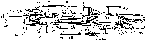
continue
from infiltration at the manhole will work on the seal, causing the seal to
begin to leak.
The infiltration then gets into the effluent that is flowing through the
manhole. Likewise
the material flowing through the manhole can get into the annular space
finding cracks
and open joints therefore exfiltrating to the surrounding soils and water
table around the
pipe.
[0005] Footprint as defined in this disclosure would be that the other
rehabilitation
methods are required to have their vehicles and equipment right at the
manhole/pipe
access to facilitate their repair process. Due to access often times being in
yards,
medians, fields, woods, creeks, etc., the vehicles tear up soils, grass,
remove trees, etc.
Most often these methods have to excavate the manhole or vault to facilitate
inserting
their liners. Often times in creek or drainage culverts the contractors have
to put their
equipment directly in the water thereby leaking oils, fuels, etc. into the
water. Also in
these applications, the thermosetting resin leaches into the rivers, creeks,
lakes, ponds,
killing fish and organisms etc., due to inflation of the "bag" or "sock" with
hot water or
steam. Additionally with cured in place, (hereinafter "CIPP") and use of high
density
polyethylene (hereinafter "HDPE") used in slip lining, the pipe capacity is
downsized so
much that the rehabilitated (narrowed) pipe increases flow velocities. This
results in
creek scour that causes loss of stream banks, plant life and animal life.
Addtionally in
these applications with the water infiltrating into the annular space through
joints and
cracks, the infiltrating water beings surrounding soils with it. In time this
results in a
large voids around the pipe and causing the formation of sink holes (economic
as well
as environmental) in roads and yards caused by soils getting into the pipe.
[0006] The method of the present invention does not create an impact of
leaching
CFC's, VOC's, or endocrine disrupters being emitted into air, water and
effluent and the
method does not cause a footprint due to the use of an umbilical allowing
equipment to
2
CA 02694490 2010-03-10
be as much as 400 feet or more from the access point of the pipe. The
umbilical can
traverse unlimited times around buildings, trees, etc via the use of roller
quadrants.
Contractors using the apparatus or method of the invention do not have to dig
up or
disrupt access paths as the umbilical is only 2" in diameter and can be
inserted into any
access.
[0007] The present invention generally relates to apparatus and methods for
applying a liner to the interior surfaces of pipes, conduits and passageways.
The
disclosure also more specifically speaks about the ability to remotely apply a
consistent
and continuous lining in a pipe. The liner is inert after application and does
not contain
and/or leach volatile organic compounds (VOC's) or chlorofluorocarbons "CFC"
or hydro
fluorocarbons "HCFC's" or endocrine disruptors.
2. Description of Related Art
[0008] Prior art demonstrates numerous methods to rehabilitate pipelines,
conduits and passageways from the inside in order to restore asset integrity.
[0009] In situ repair methods incorporating a resin impregnated fiber lining
tube
are described by Wood et al, US Patent number 5409561 and Kliest, US Patent
6427726. In these cured-in-place (CIPP) methods, conventional resins include
polyester, vinyl ester and even epoxy resin form a matrix with a tubular
textile material,
positioned within the deteriorated pipe section, are forced into intimate
contact with the
pipe interior surface and allowed to cure. The cure time may be hours or days.
There
are many instances and conditions where the above methods are either not
practical or
are unsuitable.
[0010] Davis Patent number US 6986813 describes utilizing a polymer product
that is sprayed onto the interior pipe walls to form a seamed monolithic
liner. A seamed
monolithic liner is created by the inability of the lining method or apparatus
to
continuously line a section of pipe. As a result there are stop points in the
lining and
replacement lining overlaps the previously applied liner, thereby causing a
seam. This
patent attempts to overcome many problems identified in prior art. Typical,
prior art
spray in type liners experience major problems as evidenced in the plugging of
spray
tips, slow curing coatings resulting in surface sags and inconsistent material
application
3
CA 02694490 2010-03-10
thickness and other constraints resulting in finished liner thicknesses in the
0.200 -
0.400 inch range, rendering them unsuitable for many applications.
[0011] Davis attempts to overcome the first constraint of spray tip plugging
by
incorporating a blow off mechanism attached to the tip of the spray gun in an
effort to
eliminate plugging during operation. Additionally, Davis purports to employ a
fast
setting material to eliminate sags. The combination of these two assumed
improvements actually result in a compounded problem. The Davis patent teaches
continuous blowing of air through the time of the spray gun as a method to
prevent
clogging. Unfortunately adding air flow to the product stream only increases
the
atomization of the spray resulting in higher static attraction to moving
parts. Purging the
spray tip with compressed air does not eliminate the plugging problem. A
splatter shield
is also mentioned to deflect errant spray material from occluding the spray
orifice. In
practical operation, the root cause of the repeated clogging of the spray tip
is more a
function of design.
[0012] In Davis, a spinning flat or slightly obliquely angled disc is used to
propel
the projected fast setting lining material onto the pipe walls. This flat or
slightly obliquely
angled spinning disc design as it relates to the direct right angle diffusion
of the spray
causes a significant amount of rebounding/ricochet lining material to
accumulate on the
splatter shield and air blow off mechanism, ultimately resulting in total
blockage of the
tip and other crucial mechanical functions within a short period of time. This
does not
allow for continuous operation or lining of more than 10-20 feet of pipe
without the need
to retract the apparatus and clean.
[0013] The spinning disc design of Davis fails to satisfy the requirement for
a
uniform lining thickness as well. As described, the resultant physics do not
afford equal
dissipation of lining material in the full 360 degrees of circumference. As
the fast setting
material is projected at the spinning disc at a generally perpendicular angle,
the high
speed of the spinning disc induces a disproportionate amount of material to
the first 90
degree arc that is quickly thrown to the pipe walls. The current apparatus due
to its flat
or slightly oblique design does not afford the coating material any dwell time
to equalize
mass and distribute the coating material around the circumference of the disc
prior to
being ejected. This ultimately results in thicker coating or lining in the
first 180 degrees
4
CA 02694490 2010-03-10
of circumferential arc of the pipe wall. This presents an unacceptable
condition when
uniformity is necessary to calculate ultimate liner properties and performance
which is
required by end users.
Static build up:
[0014] There is no consideration in prior art for the disruption caused by
static
build up.
Static build up is caused by the high rpm's of the shaft and disc as they
relate to close
proximity to pipe wall and the inherent need due to lining cure. Forced air is
not a cure
for static build up. Static build up is controlled through high pressure and
high heat
impingement of the lining components only. The forced dry air is to keep the
pipe
surface as dry as possible and to keep product mist from coating camera lenses
as well
as to force dry air to assure a dry working environment for the apparatus.
[0015] Static build up in prior art is compounded by the fact that the
apparatus
uses a "spray" pattern to send material from the tip to the spinner disc. This
spray
naturally causes atomization of the lining material which results in more
static charge
and also makes it easier for the static attraction of the shaft and disc to
"pull" the
material as it passes by these parts.
[0016] This static attraction between coating materials and the shaft/disc
result in
material stalactites and stalagmites depending on their positional
relationship to these
devices.
[0017] These formations will in time severely impede if not halt the
apparatus'
ability to continually line the pipe.
[0018] The build up of these formations will divert the flow from the tip to
the
spinner disc resulting in additional disproportionate distribution of coating
material to the
pipe wall.
[0019] Formations continue to grow as the lining process proceeds.
[0020] Formations eventually break off due to their increased weight and
centrifugal force being applied.
[0021] Formations that get imbedded in the uncured liner causing profiles in
the
flow channel that will result in diminished flow capacity of the liner due to
increased
CA 02694490 2010-03-10
coefficient of friction. Also the imbedded pieces causes "snag" areas in mixed
effluent
pipelines such as sewage which results in solids - toilet paper etc - getting
caught on
them and building up sometimes to block pipeline flow.
[0022] Formations that are imbedded in the in the first few oscillation
strokes of
the apparatus end up diverting or blocking the coating material from ever
reaching the
pipe wall due to the straight projection off the spinner disc. This creates
through voids
in the finished liner.
[0023] This situation results in the need to remove the prior art apparatus
from
the pipe and clean many times to actually complete a full liner application
hence
diminishing the claims of a faster method in prior art.
Spinner Disc Build Up:
[0024] Current art has an inherent design that has no way of stopping the
build
up of coating material on the spinner disc.
[0025] In prior art the spinner disc is subject to a "spray" formation from
the tip.
[0026] Utilizing a spray pattern creates a "dry fall" effect at the point the
coating
hits the spinner disc. This does not allow the disc to totally disperse the
lining material
as the material does not have the weight and mass needed to completely propel
off the
disc effectively. It does not have the wet out capabilities of a tightly
uniform stream of
lining material as taught by the instant disclosure.
[0027] In prior art, spray is immediately propelled from tip at a set pressure
which
in turn slows the rpm of the spinner disc due to direct force applied by the
sprayed
coating material velocity. The initial required rpm is then never fully
achieved. The
spinner motor from this point on is trying to regain the initial rpm with
failure.
[0028] A standard pneumatic motor is used in the prior art. The pneumatic
motor
produces high rpm's and low torque. Air motors have been found to be a
necessity as
electric motors with high rpm/high torque are too large for the apparatus in
small
diameter pipe. Hydraulic units work but the need to supply hydraulic pressure
at 500
feet requires bulking up the umbilical with hoses, adding costly pumps and
additional
weight and diameter to the umbilical.
[0029] The above mentioned "dry fall" effect starts to gradually slow the rpm
of
the spinner disc due to the weight of the resulting build up. As the rpm slows
due to low
6
CA 02694490 2010-03-10
torque, the effect becomes greater and greater having a"snowbalP' effect on
the
apparatus, completely stopping the spinner disc and ultimately rendering the
apparatus
incapacitated in as little as 10 minutes.
[0030] This results in lining material still being projected from the tip
without being
dispersed by the disc. The material then drips to the bottom of the pipe
resulting in piles
of lining only on the bottom of the pipe.
[0031] This results in the need to constantly remove the apparatus from the
pipe
and clean the shaft and disc which can take hours then reinserting to once
again line for
a short amount of time. This is a constant procedure with prior art. This
consistent
required retraction and insertion can result in inter-coat de-lamination of
the liner due to
possible contamination of the already installed liner while the retraction
process and
cleaning process is being completed.
[0032] In prior art it is stated that the apparatus can line for hours and
from
intervals of 300-600 feet. This, however, is not possible in a single
insertion and
retraction cycle. This adds considerable time to the process evacuating any
advantage
in time or economics over other lining methods as stated in prior art.
Trajectory geometry:
[0033] Prior art utilizes a flat or maximum oblique angle in its spinner disc.
This
design results in a straight stream of dissipation off the spinner disc.
[0034] Prior art uses relatively slow oscillation of the spinner disc rod with
long
smooth linear strokes to overlap material to prevent sags and runs. This
remains a tight
straight dissipation stream off the disc throughout the oscillation cycle.
[0035] The apparatus only coats in one direction in the pipe to complete the
coating.
[0036] All pipe has a natural profile whether it be at bell/spigot joints,
welds,
tuberculation etc.
[0037] The prior art does not have the ability due to its design, mechanics
and
straight or right angle stream to completely line the forward or backward edge
of these
profiles as it relates to the position of the apparatus. The forward side of
these profiles
do not get coated and therefore there are exposed areas in the existing pipe
wall.
7
CA 02694490 2010-03-10
[0038] Prior art also does not have the ability to reverse the rotation on the
spinner disc. There are many times in pipe where there will be a lateral
intrusion - a
small pipe sticking into the main pipe - the maximum penetration is usually
3/". In this
instance there is no way that lining can be placed on the underside of this
intrusion pipe
or any profile for that matter without counter rotation. The apparatus of the
instant
invention has the ability to counter rotate either through transfer or air
from exhaust to
intake and reverse. More typically this is done through electronically
switched bi-
directional transmission or transfer case that is in between the shaft and the
air motor
collet. The reason for this is that on high rpm air motors they easily wear
out if they are
run in both directions. Compounding this problem in the prior art is that the
unit does
not have the ability to start and stop flow. Flow must be stopped while the
motor is
being reversed in rotation.
Multiple starts and stops:
[0039] Prior art design and mechanics do not allow to open and close the
valving
rod or spray tip stopper more than one open and close cycle. The prior art
uses a spray
tip orifice that is machined so that the valving rod seats inside it. When
this is open,
spray comes through the orifice. It is then closed and residual mix material
encapsulates this area and basically locks it into that position. The prior
art mechanics
does not have the pull force or the ability to have a momentum surge on the
valving rod
to break this free - hence the valving rod cannot be remotely opened up more
than one
cycle - open/close - done. The present invention apparatus uses a different
sealing
method at the interface of the termination rod (valving rod in prior art) end
and the
stream orifice to seal - mixed product encapsulation of the area is made to be
a
minimum through this design. The instant invention also has a different design
of the
termination rod actuator - it has a much higher pull force coupled with a
function that
allows for some "free" pull force momentum to build prior to actuating the
termination
rod. This allows the rod to brake free therefore allowing unlimited open and
close
cycles.
[0040] Regarding the prior art, in the event that there is a malfunction in
control
systems or an impediment of the umbilical retraction which is common, the
apparatus
8
CA 02694490 2010-03-10
must be disengaged from continuing to spray. If not the result is heavy rings
in the liner.
If this event happens the apparatus must be retracted from the pipe and the
impingement block completely disassembled, cleaned, reassembled and re
inserted into
pipe. This is a very time consuming process. This design and mechanical flaw
also
does not allow the apparatus to complete sleeve or individual repairs in the
pipe unless
you do them one at a time due to the necessity to clean after every valving
rod cycle.
Dimensional Restrictions on Insertion and Retraction:
[0041] Equipment of the prior art, due to its overall length, cannot be
inserted or
retracted from an underground pipe with the access being a manhole or vault
with a
diameter or horizontal dimension or less than 5 feet.
[0042] This overall dimension is the direct result of the claims for the
method/mechanics of oscillation to afford slow dissipation and overlapping of
the lining
material.
[0043] Additionally the 23" bend radius and mechanics of the attachment
bracketing of the prior art umbilical is such that it significantly increases
the overall
dimension of this apparatus.
[0044] Typically in the private sector and in the municipal market sectors all
underground pipes are only accessible through the above mentioned accesses.
Rarely
is there excavation afforded to allow insertion of apparatus into the pipe.
The prior art
apparatus can be disassembled then reassembled as it is being inserted in the
pipe.
This is a very time consuming process. This, however, does not afford this
apparatus
the ability to coat the entire pipe. The unit must stop lining to be
disassembled on
retraction. This stoppage must occur in manholes and vaults with a diameter of
horizontal dimension of less than five feet. This results in as much as 16"-
30" of pipe
not being coated in a typical manhole or vault. There is currently no
acceptable way
afterward to line this section that is void of lining material. Prior art
creates a void or in
the pipe lining for the pipe not the manhole. Due to its length from the
oscillation stroke,
the umbilical bend radius and equipment design, the prior art lining equipment
has to be
stopped in a 4' manhole with 30' of the robot still inside the pipe. At this
point all lining
9
CA 02694490 2010-03-10
processes must be stopped. There is no way after this in a small diameter pipe
to get in
and manually line the pipe section that was missed.
[0045] Due to the design and mechanics of the prior art, it cannot line
vertical
pipe or pipe with a slope of more than 30 degrees.
Diameter:
[0046] Due to the design and mechanics of the prior art, it cannot be utilized
in a
pipe with a diameter of less than 10". Prior art states that it can be used in
6" pipe. The
basic dimensions however do not allow for this as filed in the drawings. This
is evident
to a person skilled in the art after examination of the detailed description
of the
equipment in Davis patent US Pat. 6986813 discussed above. Review of the
description and drawings demonstrate it would be impossible to be short enough
or
narrow enough to fit into a 6" pipe.
[0047] Over and above the fact that the unit's dimensions restrict its ability
to line
pipe with diameters less than 10", its function of mechanics also severally
impedes this
ability. The unit utilizes oscillation. This results in all oscillating parts
to be on the
exterior of the apparatus and in close proximity to the pipe wall. No matter
how long the
determined length of that oscillation may be (5"-36") the entire length and
width of the
carriage or shuttle plate is moving. Pursuant to prior art drawings this
length is longer
that the length of the base assembly when the spray head is considered.
Example: if
the oscillation is set for 10", the entire length of the unit is moving 10" on
every stroke
exposing the entire length to profile or offsets. The full width and length of
the upper
apparatus shuttle plate is in motion. The apparatus as designed also has many
right
angle projections that can get caught on joints and or profiles in pipe wall.
[0048] Additionally due to the apparatus design and mechanics as it relates to
external part oscillation it is very easy for it to get "hung up" in small
diameter pipe. All
pipe systems have profiles, sags and offsets. When the current apparatus
encounters
these obstructions it will stop the oscillation process. This may only be
momentary or
for extended lengths of time. In either case it causes a build up or "ringing"
in the new
coating which is unacceptable. If the stoppage of oscillation occurs for an
extended
CA 02694490 2010-03-10
length of time it can actually close off the pipe entirely with lining
material and/or lock
the apparatus in the pipe.
[0049] The external oscillation parts are all on the exterior of the unit.
This
exposes them to all the overspray and existing contaminants that are in the
pipe while
being coated. This eventually impedes their function resulting in diminished
capabilities
or incapacitation.
SUMMARY OF DISCLOSURE
[0050] This disclosure teaches an in situ pipe liner spay apparatus and method
that allows spraying of an isocyanate and amine resin mixture or other
mixtures onto the
360 circumference of the pipe interior wall. The mixture can line the pipe
walls. The
lining components are mixed in correct proportion in the impingement block of
the
apparatus within the pipe. The components may be heated within the apparatus
for fast
reaction and curing on the pipe walls. This avoids slumps or other undesirable
variations of the lining layer. The device can apply a lining thickness of
between 0.05"
and in excess of 4" in a single pass of the spray assembly.
[0051] The apparatus includes an umbilical comprising at least one air hose,
at
least one electrical power cable, at least one video communication cable and
lining
component hoses. The housing of the apparatus includes at least one heater for
heating the lining components.
[0052] The disclosure teaches an in situ pipe liner spray apparatus having a
reciprocating capability (forward and reverse) of between 0.001" and 5.00"
controlled by
a reciprocating head. This means the dissipation device and rotating shaft
longitudinally
moves back and forth relative to the apparatus (hereinafter termed "forward
and
reverse"). This allows the apparatus to apply multiple layers of lining to the
pipe. The
dissipation device comprises a dissipation device shaped as two asymmetrical
reversely
aligned cones with a center top attached to a rotating shaft (extending from
the
apparatus rotating head) and with an acute angled flange oriented to the
reciprocating
head.
11
CA 02694490 2010-03-10
[0053] The reciprocating head of the apparatus includes an impingement block
wherein the impingement block mixes the lining components and projects the
lining at a
specific angle of trajectory to the dissipation device.
[0054] The apparatus pressurizes the liquid lining material and allows it to
exit
from a impingement block nozzle maintaining a near constant diameter stream
prior to
contacting a conical rotating dissipation device (hereinafter "dissipation
device"). The
surface of the dissipation device forms an acute angle to the lining stream.
The
dissipation device may rotate at 20,000 to 45,000 RPM at high torque of
approximately
20 foot pounds.
[0055] The rotational direction of the dissipation device can be remotely
changed
from clockwise to counter clockwise. The pressures, velocities and flow rates
of the
lining material stream can be remotely adjusted to the apparatus via the
umbilical
connection that is directed out of the stream orifice (or spray tip) to the
dissipation
device.
[0056] The dissipation device has an inverted conically sloped surface contact
area proximate to the center top for receiving the lining material stream that
decelerates
the pressurized stream flow inertia and evens the material dissipation into
the outer
flange. The dissipation device is designed to be self cleaning by its rotation
function
and pressurized trimming of excess material, thereby eliminating material
build up.
[0057] The dissipation device also allows a dwell time for material to evenly
distribute inside the compounded conical geometry of the diffusion device
prior to being
cast onto the pipe wall. This facilitates a symmetrical lining layer on the
pipe surface.
[0058] The apparatus subject of this disclosure also discharges negatively
charged ions over the rotating shaft and dissipation device. This impedes
static charge
and the resulting coating material build up.
[0059] Utilization of a shaft scraper appendage eliminates build up due to any
possible static charge or material overspray residuals on the spinner shaft.
[0060] It will be appreciated that the linings may have a cure time of 3
seconds to
one minute, thereby allowing the application of multiple layers of lining. The
apparatus
subject of the disclosure may line pipes having interior diameters between
5.5" and 54".
12
CA 02694490 2010-03-10
[0061] One must first fully grasp the need for exact and precise
methods/mechanics required to utilize a remote device for dispensing an ultra
fast cure
lining material in a pipe and especially in small diameter pipe. Any design
flaw,
mechanical flaw, or controls system flaw will cause the system to fail in a
matter of
seconds. These failures can be catastrophic. The material being dispersed
typically
flash cures or gels in 4-6 seconds. It only takes an instant for the apparatus
to become
totally incapacitated or even cause its own self engulfment and to get
permanently
lodged in smaller diameter pipe. While prior art suggests that its methods and
mechanics will improve the current technology in spray lining, it does not. It
appears
that the prior art was only tested and utilized in a lab environment and never
tested
under real world conditions. The prior art was based on evidence established
in short
segments of test pipe under ideal conditions. Underground pipe has no ideal
conditions.
BRIEF DESCRIPTION OF THE DRAWINGS
[0062] Figure 1 illustrates the apparatus subject of this disclosure.
Illustrated is
the dissipation device, rotating shaft, impingement block, reciprocating head,
front
housing and rear housing. Also illustrated are the articulation junctures
between the
housings and the reciprocation head.
[0063] Figures 2 & 3 are side views of the apparatus showing the change in
position of the reciprocating head to the front housing.
[0064] Figure 4 is a cross sectional view of the dissipation device showing
the
path of the liner on the device and off the outer device flange for lining a
pipe wall.
[0065] The accompanying drawings, which are incorporated in and constitute a
part of the specification, illustrate preferred embodiments of the invention.
These
drawings, together with the general description of the invention given above
and the
detailed description of the preferred embodiments given below, serve to
explain the
principles of the invention.
13
CA 02694490 2010-03-10
DETAILED DESCRIPTION
[0065] This disclosure teaches a method and apparatus that allows remote
installation of liners inside pipes for distances exceeding 1,000 linear feet
with only one
insertion and one extraction of the apparatus. In one embodiment, the liner is
a reaction
product of isocyanate and amine resin mixed in situ at high temperature and
pressure
immediately prior to spraying the liner on the pipe wall. In one embodiment,
the
temperature may be within the range of 140 F to 170 F with the ideal
temperature of
155 F. The pressure of the liquid components may be between 1700 psi to 3500
psi
depending upon the viscosities of the materials and the necessity for
molecular cross
linking. The cured liner is inert and free of VOC's, carbon fluorocarbons and
endocrine
disrupters. The cured liner is impervious to influent and effluent. Therefore
a liner
installed with the apparatus of the invention and the method disclosed herein
will stop
effluent from entering the ground and ground water.
[0066] The disclosure teaches an apparatus that by its design can be remotely
inserted and retracted from all manholes and/or vaults with
diameters/horizontal
dimensions of approximately 18" while still achieving the lining of the entire
pipe.
[0067] The apparatus of the disclosure teaches an internal forward and reverse
assembly, i.e., reciprocating head, rotating shaft and dissipation device,
allowing it to be
fully functional in small diameter pipes with bends, sags, offsets and joints.
The
apparatus utilizes articulated junctures separating housing sections and the
reciprocating head.
[0068] Figure 1 illustrates a prospective view of one embodiment 100 of the
disclosure. Illustrated is the dissipation device 400 mounted on a rotating
shaft 110.
The rotating shaft extends into the reciprocating head 105 to an air turbine
motor (not
shown). Mounted on the top of the reciprocating head are the impingement block
111,
the connected termination rod 121 and the termination rod actuator 120. The
forward
housing 102 extends from the articulating juncture 103 separating the
reciprocating
head and the forward housing. Mounted on top of the forward housing are
television
cameras. Mounted beneath the housing are wheels 108. Also mounted to the
housing
are skids 106. Separating the forward housing and the rear housing 101 is the
articulating juncture 109. Also illustrated is the umbilical 104 containing
air hoses, liquid
14
CA 02694490 2010-03-10
liner components, television cables and electrical wires. The apparatus is
shown on an
interior pipe surface 485.
[0069] The apparatus is moved at a continuous predetermined speed through the
pipe. The articulating spaces between the housing segments and reciprocation
head
allow the apparatus to traverse around bends in the pipe or over protrusions
in the
bottom of the pipe. The direction of rotation of the dissipation device is
reversible. This
allows the dissipation to line all sides of a protrusion within the pipe
interior. There are
many times when there will be a lateral intrusion, e.g., a small pipe sticking
into the
main pipe. The maximum penetration is usually W. In this instance there is no
way
that lining can be placed on the underside of the intruding pipe or any
profile with
counter rotation. The dissipation device can be counter rotated either through
transfer
of air from exhaust to intake and reverse. More typically this is done through
electronically switched bi-directional transmission or transfer case that is
that is between
the shaft and the motor collet. (High rpm air motors easily wear out if they
are run in
both directions. The impingement block also has the ability to effectively
stop and
restart liner flow as required in the rotation reversing process.
[0070] The apparatus has a compounded effect through the cohesive mechanical
action on the dissipation of the material stream on to the pipe walls. Through
the action
of the fast high velocity forward and reverse action and the instantaneous
stop/start
action at the end of each reciprocal stroke, the cohesive mechanical action
promotes a
"bullwhip" or "wave" geometry of liner material with high velocity. The
resulting
dissipation stream assures the lining of all sides of profiles (protrusions
and insets) in
the pipe wall and is not contingent on the apparatus lining in two different
directions to
achieve full coverage of these profiles. Additionally, the remote control of
the apparatus
to reverse the rotational direction of the dissipation device affords it the
ability to apply
lining to the underside of profiles (protrusions and insets). The shape of the
dissipation
device is designed to be self-cleaning of the lining material through the
operation of
rotational forces and the cutting forces of the pressurized product streams
velocity.
[0071] The apparatus maintains the unlimited ability for the supply stream to
be
remotely started and stopped or adjusted to facilitate stopping for control
malfunctions,
and the installation of joint sleeve only applications and spot repairs - in
pipeline with the
CA 02694490 2010-03-10
need to retract and clean the impingement block in-between every start and
stop
function. Sleeves are installed in line segments of pipe. They are typically
from 2' to 8'
in length. Often the pipe is in suitable shape but there may simply be small
segments
that have cracks or offset joints. In this instance the apparatus would be
inserted in the
same manner however it would be precisely located at these areas to only line
these
segments in lieu of the whole pipe. With the ability to stop and start the
apparatus
unlimited times many of these sleeves can be installed. Sometimes customers
will only
want a 3' sleeve installed over joints only with the joint being in the center
of the sleeve.
Installation of these seams is facilitated by use of the video camera at a
control station.
[0072] A method and apparatus that can line pipe, conduits, structures and
passageways from horizontal through varying degrees vertical to fully
vertical.
Operation in a fully vertical position would require change in the roller
quadrants and
guides as they would have to be elevated and centered over the full vertical
pipe
application.
[0073] The apparatus subject of this disclosure comprises an umbilical
conveying
pressurized air and liquid components of the lining material. The two
insulated high
pressure fluid hoses are heated via a 120V loop circuit. Also included in the
umbilical
are two twelve wire KevlarTMT"^ reinforced communication cables. The umbilical
includes one or more high heat resistant KeviarTM reinforced fluid (air)
hoses. The
umbilical completely encapsulates the hoses and cables in a dive line KevlarTM
reinforced semi rigid molded polyurethane sleeve to accommodate strain relief.
Other
cables or tubes may be connected to the apparatus through the umbilical. There
may
be a tether attached to the apparatus. The umbilical or tether may extend to
the ground
surface or to a manhole. The apparatus is remotely controlled by means of the
tether or
umbilical. The umbilical has a bend radius of approximately between 8" and 12"
due to
the method of umbilical reinforcements for pulling the robot.
[0074] In one embodiment, the umbilical fluid hoses (containing component
liquid
portions of the liner material) are terminated with a split port coupling
block with
individual shut off valves. The coupling block can be attached to a receiving
block.
Both blocks may be located in the lower portion of the rear housing (described
infra).
16
CA 02694490 2010-03-10
[0075] It will be appreciated that the liquid liner components are under high
pressure. In one embodiment, the receiving block is machined to accept
coupling block
with a high pressure seal face and is vertically ported to accept fluid flow
from the
coupling block. The receiving block is also horizontally ported and threaded
at a right
angle to vertical ports to receive common JIC fittings. 90 degree JIC fittings
are
mechanically attached to the receiving block to face in reverse of the forward
end of the
rear lower housing. In this embodiment preformed radius fluid hoses extend in
a
reverse direction to the rear lower housing unit for a determined length. The
preformed
fluid hoses have an approximate 2" radius achieving a horizontal orientation
toward the
rear lower housing unit. Preformed fluid hoses attach to '/4" ID rigid high
pressure
stainless steel flare tubing. The tubing is incorporated into machined grooves
in both
lower rear housing and forward lower housing unit. The tub.ing is split and
then rejoined
with flexible fluid hoses at the articulation juncture between the rear
housing unit and
the forward housing unit.
[0076] In one embodiment of the apparatus, the apparatus is comprised of
several housing components with articulated junctures between the attached
housing
units. The umbilical feeds into the housing unit designated the rear housing.
Side
panels of the housing unit can be opened to provide access to equipment,
cables or
hoses.
[0077] The housing units may contain one or more heaters for the liquid liner
components. Polyurea, the product of the mixture of isocyanate and amine
resin, needs
to mix between 140 F and 170 F to acquire the physical properties and full
cure. The
fluid in the apparatus lines cools quickly. In prior art applications of pipe
less than 24",
there was not sufficient flow through the lines to stop the product from
cooling.
Accordingly the qualities of the lining were poor. In the event the unit had
to stop for
even a few seconds the product cooled too much to start lining. This was due
to
viscosities becoming very rapidly thixtropic - again as it will shoot out
poorly mixed
product that is of "goo" consistency and will not flow. The instant
application teaches
heating the product continually to the point of entering the impingement
block. This
achieves consistent proper mixing and the ability to start and stop unlimited
times as
17
CA 02694490 2010-03-10
well as simply stop and let the apparatus sit in the pipe for hours and then
start lining
again. The temperature also affects the cure time of the mixture.
[0078] The housing unit may also comprise top mounted electric lamps to
illuminate the pipe for the video cameras. This illumination can be
particularly useful in
large diameter pipes. The next housing unit is designated the forward housing
unit. It
may contain an air ionization unit generating negatively charged air. It also
contains a
heater for the lining components.
[0079] At least one video camera may be mounted on the top of the forward
housing. The camera may contain built in infrared lighting to supply light for
the
camera. Multiplex video/control cables extend through the umbilical and may be
connected to the apparatus via common friction fit electrical connections.
Electrical
connectors are attached to the apparatus via common threaded, braided
stainless steel
strain relief fittings attached to the rear housing vertical face machined
borings. Once
inside the lower rear housing unit, the wires are split. Wires are terminated
at the
solenoid for the function of the solenoid unit. Wires traverse through the
rear lower
housing unit in the same manner as the air lines and may be terminated in two
250V
relays that are mounted in machined recesses in the forward upper housing
unit. These
relays work in conjunction with the air solenoid to facilitate in and out
functions of the
pneumatic actuator for the reciprocating head. Relays may also be connected
via wires
to electromagnetic sensors that are attached to the exterior of pneumatic
actuators.
The sensors are fully adjustable along the exterior of the actuators to adjust
the stroke
length of the actuator function. The stoke length may be determined by the
user
depending upon the application. In the case of electromagnetic rod actuators,
these
wires supply power and function to a programmable logic controller (PLC) and
actuators.
[0080] The pneumatic or electromagnetic reciprocation actuator can be affixed
in
the forward lower housing unit. Actuator rods traverse through the forward
lower
housing unit via machined bore in the vertical face of the housing unit and
are attached
to rear vertical face of the reciprocation head. The reciprocation head is
attached to
the forward lower housing unit via steel alignment rods via threaded borings
in the
vertical face of the rear reciprocation head. The alignment rods extend
reversely and
18
CA 02694490 2010-03-10
longitudinally parallel to reciprocation head and penetrate orifices of linear
bearings set
in machined recesses in between upper forward housing unit and lower forward
housing
unit. These alignment rods maintain reciprocation head alignment during the
reciprocation function. They are protected from damage by enclosure within the
front
housing unit and the reciprocation head.
[0081] Further, a pneumatic or electromagnetic controlled termination rod
actuator is affixed to the top of the reciprocation head. As will be
discussed, the rod
actuator controls the termination rod which penetrates the impingement block.
The
impingement block mixes the liner components and projects the liner to the
dissipation
device extending in front of the reciprocation head.
[0082] In one embodiment, the termination rod actuator's stroke length in the
pneumatic function is a set non-adjustable 3/8". The pneumatic actuator's
function is
controlled via electrical signal to the solenoid in the rear lower housing
unit as
previously discussed. The electromagnetic actuators function is controlled via
the
programable logic controller (PLC).
[0083] The reciprocating head is attached to the front housing at an
articulating
juncture. The reciprocating head is moveable in relation to the forward
housing. The
reciprocating head can move along the longitudinal axis of the pipe in a
forward or
reverse direction in relation to the forward housing. This is sometimes
referred to as an
oscillating motion. In one embodiment, the head moves between 0.001 and 5
inches.
The movement of the reciprocating head moves the impingement block and
dissipation
device in unison. The reciprocating housing moves on rods extending internally
within
the housing and reciprocating head. This is unlike the prior art and protects
the steel
rod, which provide stability to the reciprocating head, from damage. The front
housing
and the reciprocating head are separated by a variable space. This is
sometimes
referred to as the common reciprocation space. A tether may be attached to the
front
face of the front housing (preferably beneath the reciprocating head).
[0084] Returning to the pathway of the fluid tubing, rigid tubing is joined
again
with flexible high pressure hose at brackets on both sides of the
reciprocating head.
Flexible tubing then extends to the impingement block coupling and is joined
to the
impingement block. The impingement block coupling is vertically ported and
machined
19
CA 02694490 2010-03-10
faced to be received by the machined upper face of the impingement block. It
will be
appreciated that the design of this embodiment allows the reciprocation head
to
reciprocate at high speed while allowing high pressure fluid hoses to
reciprocate at the
point of the mentioned radiuses at the rear housing.
[0085] One embodiment of the air pathway from the umbilical attaches via a
quick disconnect fitting that is extended in reverse from the lower housing
through
machined borings in said vertical face of the rear housing unit. An air hose
which
extends reversely from rear lower housing unit is affixed to rear housing unit
via
stainless steel braided strain relief. Inside the rear housing unit, the air
hose is split via
common fitting into to 3/8" ID flexible hoses.
[0086] One flexible hose is attached via common fitting to a 4 way 24VDC
common solenoid valve mounted in the rear housing unit. The other flexible
hose
continues through the multiple machined bored orifices, vertical faces of rear
and
forward housing units. This flexible hose then terminates at the front housing
unit front
face machined boring. At this termination the air flow is re-established
through
extendable and retractable pre coiled flexible air hose to facilitate
reciprocation at the
common reciprocation space. This pre coiled air hose terminates at the rear of
the
reciprocation head and is mounted in a pre bored orifice in the rear of the
vertical face
of reciprocation head. The air flow is re-established through the flexible air
hose and is
connected to the turbine air motor.
[0087] Figures 2 and 3 illustrate the operation of the pre-coiled flexible air
hose
122 located in the articulated juncture 103A between the forward housing 102
and the
reciprocating head 105. It will be appreciated that the reciprocating head
extends
forward from the forward housing in Figure 3. Also illustrated is the
dissipating device
400, the rotating shaft 110, the shaft scraper 112, the impingement block 111,
the
termination actuator 120 and the termination rod 121. Also illustrated are the
front
wheels 108 and the back wheels 107, the rear housing 101, the umbilical 104
and the
articulated juncture 109 between the rear housing and the forward housing.
Also shown
is the pipe wall 485.
[0088] The second flexible hose at the split in the rear housing unit is
attached to
the solenoid for air flow to the solenoid. The solenoid affords the splitting
and control of
CA 02694490 2010-03-10
four separate actuation or flow sequences. One hose from the solenoid
traverses
forward through the rear housing unit and is connected to a common fitting at
the
vertical face boring in the forward housing unit. Flexible hose is then re-
established via
a fitting in the articulation space between the back and front lower housing
units. The
flexible hose is then reattached to the back vertical face of the forward
housing unit.
The flexible hose is then re-established inside the forward housing unit and
is
connected to by common fitting and flow control valve to the "push" intake
port of a
pneumatic actuator that affords a reciprocation function. A second flexible
hose form
the exhaust port in the solenoid travels with the exact same path and design
as the first
hose but connects to the "pull" end of the pneumatic actuator via a common
fitting and
flow control valve. In pneumatic sequencing for reciprocation, the speed of
reciprocation is adjustable via the flow control valves. In electromagnetic
sequencing,
the reciprocation speed is determined by adjustment of the programmable logic
controller (PLC) via electrical current. It will be appreciated that an
electromagnetic
actuator does not need the air supply and is controlled via electrical current
and PLC
which replaces the solenoid.
[0089] The third and fourth flexible air lies from the exhaust ports of the
solenoid
travel with the same design and path as the air lies to the pneumatic actuator
but
traverse through the front lower housing unit in the same fashion as the
turbine motor
air supply as stated earlier. These two air lines then connect via common
fitting to the
"push" and the "pull" ports of the pneumatic termination rod actuator which is
located
and mounted on the top of the reciprocation head.
[0090] It should be noted that the pneumatic termination rod actuator is often
replaced with an electromagnetic rod actuator for certain applications and is
controlled
with an electronic PLC in lieu of a solenoid. With both the reciprocation and
termination
rod functions, it is a quick retrofit to interchange these methods.
[0091] A termination rod actuator and termination rod are mounted on top of
the
reciprocating head. The termination rod is extendible into an impingement
block. The
action of the termination rod is simply one forward one reverse stroke of the
rod that
opens and closes the stream orifice. The two heated components of the liner
material
come together and are mixed in an adjustable impingement module inserted into
the
21
CA 02694490 2010-03-10
impingement block. The module is attached to the isocyanate and amine resin
product
feeds. In one embodiment, the isocyanate enters at the rear of the module and
the
amine resin enters at the front of the module. The module may be adjustable by
creating up to six orifices that line up with the feed orifices of the
impingement block. A
variation in size of the drilled orifices adjusts the amount of flow based on
volume and is
in direct relationship to the viscosity of the isocyanate and amine resin. The
module is
slid over the termination rod. The module fits into the front of the
impingement block. A
male fitting of the module fits through the impingement block. The stream tip
is pushed
onto the male component of the module. A stream tip cap is then threaded on
the
impingement block, thereby locking the module in place. Air is supplied to the
stream
tip cap via a small boring in the front of the impingement block. The air is
supplied to
this boring via a channel that is cast in the impingement block and in which
has an
opening orifice on the bottom of the block. A small air line is connected to
this orifice to
supply air to the channel and ultimately to the spray stream cap. There may be
a
second threaded connector on the back side of the impingement block at the
orifice.
This connector comprises a threaded sealing nut with a vicon seal that
compresses
against the termination rod.
[0092] The termination rod penetrates through the front and back of the
conical
shaped module mounted within the impingement block. When the termination rod
is
fully extended forward, the end of the rod is seated on the back side of the
stream tip to
seal the liner flow. When the termination rod is retracted, the rod end passes
through
the drilled module orifice allowing product to flow into the module orifice
and mix at high
pressure. The product then streams from the stream tip to the dissipation
device.
[0093] The two components of the liner material come together and are mixed in
the impingement block. The components are isocyanate and amine resin.
[0094] The termination rod actuators are attached to machined termination rods
via machine threads. Termination rods traverse forward from the actuator
connection in
a slight downward and adjustable angle. The termination rod penetrates
impingement
block in the center preferably with a compression fitting with a kalrez seal
and orifice
that is attached via a threaded boring in the impingement block. The
termination rod
then traverses through a polymer module until it reaches a termination point
at the back
22
CA 02694490 2010-03-10
recessed side of a machined stream tip. The stream tips may be machined with
variable sized orifices from 0.015" to 0.090" depending upon the flow needed
for the
particular lining application. The instant invention also has a different
design of the
termination rod actuator - it has a much higher pull force coupled with a
function that
allows for some "free" pull force momentum to build prior to actuating the
termination
rod. This allows the rod to brake free therefore allowing unlimited open and
close
cycles.
[0095] The polymer module has a 0.125 longitudinally ported orifice to receive
the termination rod. The termination rod is self sealing due to light
compression to the
module surface. The module is drilled with orifices at right angle to the
longitudinal
orifice in the module. These orifices range from 0.010" to 0.080 depending on
the flow
needed. The orifices serve as supply ports for the lining components. A
minimum of
two and a maximum of six orifices are drilled into the module at right angles.
These
orifices facilitate the flow of both components of the lining material from a
spray tip. It
will be appreciated that the lining components are separated completely and
maintained
in separate storage containers until they impinge at high pressure and heat
inside the
mixing module as described above. Upon mixing in these conditions (heat and
pressure), there is a snap cure of between approximately 3 seconds to 1 minute
depending upon the product and application criteria. In one embodiment
utilizing the
reaction product of isocyanate and amine resin, the product cures in
approximately 5
seconds.
[0096] The components enter the impingement block separately and enter into
the chambers via machined orifices. The chambers may contain a mesh screen to
filter
impurities out of the components. These screens may also be in line in various
impingement block designs depending on size constraints of pipe to be lined.
Once
filtered, the product flows via orifices to the face of a recessed orifice in
the
impingement block that holds the described module. This recessed orifice has
circumferential groves in which align with the pre drilled orifices in the
module. Once
under pressure, these grooves fill up with product. Upon remote activation of
termination rod, the rod is partially retracted reversely out of the module
orifice allowing
product in grooves to enter the mixing chamber via pre drilled orifices. The
product is
23
CA 02694490 2010-03-10
then projected due to applied pressure through the stream tip orifice and a
predetermined and adjustable angle to be received on the landing slope of the
first
inverted conical section of the rotating dissipation device. This landing
slope is
proximate to the center top of the dissipation device.
[0097] The dissipation device may be comprised of high density nylon, KevlarTM
reinforced nylon, or metal. Other materials may be used such as fiber
reinforced
polymers. The angles of the side walls of the dissipation device may be
approximately
80 degrees for the center top and approximately 60 degrees for the outer
flange.
[0098] The reciprocating head also contains a high velocity and high torque
air
turbine motor. This motor powers a rotating shaft that extends from the front
of the
reciprocating head. In one embodiment, the rotating shaft is 12 inches long.
In
another embodiment, the rotating shaft is 6 inches long. The rotating shaft
may be
comprised of high density nylon, KevlarTM reinforced nylon, or metal. A
dissipation
device is mounted on the end of the rotating shaft and at a preset distance
from the
impingement block. The dissipation device can rotate between 20,000 and 45,000
rpm
at high torque of approximately 20 foot pounds.
[0099] Mounted on the reciprocating head adjacent to the rotating shaft is an
optional shaft scraper. This long slender device removes overspray and
deposits on the
rotating shaft.
[0100] Proximate to the mounting hardware of the shaft scraper is the air tube
outlet for the air ionization unit generating negatively charged air. This
generator may
be located in the first rear housing with a tube traversing the front housing
and into the
reciprocating head. The tube blows a stream of negatively charged air across
the
rotating shaft and into the dissipation unit. This eliminates static. Static
electricity
entraps small quantities of the liquid liner onto surfaces of the apparatus,
i.e., the
rotating shaft and dissipation device. The entrapment continues until the
rotating shaft
and dissipation device are heavily coated and their function is interrupted.
This can
force shut down of the apparatus for cleaning before lining can continue.
[0101] The operation of the shaft scrapper and ionization unit result in
continuous
lining of the pipe. This lining process benefits the environment by creating a
well
24
CA 02694490 2010-03-10
bonded and uniform thickness pipe liner. The absence of fault minimizes the
migration
of effluent from the pipe.
[0102] The design of the dissipation device minimizes unintended and undesired
back spray upon the lining apparatus. Prior art using an oblique or flat
rotating device to
disperse the lining mixture has experienced spray blocking the spray tip.
[0103] The forward and reverse motion of the reciprocating head may cause the
dissipation device to move forward and reverse between 0.001 to 5 inches. The
impingement block and termination rod are mounted on top of the reciprocating
head,
thereby causing the stream from the impingement block to maintain its fixed
relationship
to the dissipation device.
[0104] The impingement block mixes the liner components. The liquid liner is
projected out of an orifice of the impingement block by the withdrawal or
retraction of
the termination rod to the termination rod actuator.
[0105] Figure 4 illustrates the liquid liner 420 streaming from the
impingement
block to the dissipation device 400. The liner streams on to the center flange
401 near
the center top 403. Also shown is the center annulus 410 where the rotating
shaft (not
shown). The liquid liner flows down the side 421 of the center flange to the
pocket 422
formed at the juncture 405 of the two opposing acute sides of the dissipation
device.
The liner material 422 has an opportunity dwell within the pocket 405 and
where the
curing process can continue. The liner material progresses up the slope of the
outer
flange and is pulled over the edge 404. The liner material is shown at the
edge 424 and
pulled 425 to the sides of the pipe wall 485 where it cures and forms and
inert liner.
[0106] Continuing, the angle of trajectory of the liquid liner causes it to
stream
onto the interior acutely angled side of the rotating dissipation device. This
is proximate
to the center top of the device. The liner strikes the dissipation device at
between 1700
to 3,500 psi dependant on material viscosities. The dissipation device is
shaped like a
letter "W". The middle portion is designated the center top. The inside
portion of the
bottom of the W is the pocket segment of the dissipation device wherein the
liquid liner
can briefly dwell and equalize its mass before being pulled over the outer
flange by the
operation of centrifugal force. Due to the rapid rotation of the dissipation
device, the
CA 02694490 2010-03-10
curing liquid liner sprayed from the device evenly lines the interior pipe in
a 360 degree
circumference.
[0107] The path of the liquid liner begins at the landing zone proximate to
the
center top of the rapidly rotating dissipation device. The liner material
descends down
the acute slope to the pocket area formed at the intersection of the interior
slope and
outer flange. The liner material progresses up toward the outer flange where
it is
thrown against the pipe wall surface. The timing of this progression is
critical in
consideration of the cure time of the liner. It is undesirable for the liner
to cure while
within the dissipation device. Also it is undesirable for the liner to be
coated onto the
pipe wall too long before it cures. This can result in the liner sagging or
migrating from
the top of the pipe. The configuration or geometry of the dissipation device
may be
specifically selected to address these concerns.
[0108] The dissipation device also has a self cleaning function. Small
quantities
of liquid liner material may migrate toward the center top. The high velocity
stream from
the stream orifice of the impingement block trims these quantities of liner
material.
[0109] The dissipation device of the instant disclosure has the ability to
counter
rotate either through transfer or air from exhaust to intake and reverse. More
typically
this is done through electronically switched bi-directional transmission or
transfer case
that is in between the shaft and the air motor collet. The reason for this is
that high rpm
air motors easily wear out if they are run in both directions. Compounding
this problem
in the prior art is that the units do not have the ability to start and stop
flow of the lining
material. Flow must be stopped while the motor is being reversed in rotation.
The flow
may be readily stop by movement of the termination rod.
[0110] In one embodiment, each housing unit is supported on skids which permit
the apparatus to be pulled through the pipe during the lining operation. The
skids may
be made of metal. This pulling may utilize a tether attached to the front
housing. In
another embodiment, the height of the skids may be adjustable in order that
the rotating
shaft and dissipation device are proximate to the center point of the circular
pipe.
[0111] In another embodiment, each housing unit includes one or more powered
wheels or tracks. The direction of the apparatus, e.g., forward and backward,
can be
remotely controlled utilizing the lights and cameras. The tracks can be
powered by air or
26
CA 02694490 2010-03-10
electricity. In one embodiment, the tracks are powered by 24V gear driven
servo
motors that are located inside the track apparatus.
[0112] Speed of the robot apparatus is determined by a formula that takes
flow/required liner thickness/pipe diameter into account. Speed is controlled
remotely
by a speed control that is wired to an encoder on the umbilical reel. This
encoder is a
2400 bit and is connected to a program logic controller (PLC). If speed is set
for
example at 2 feet per minute, the encoder adjusts the reel speed automatically
no
matter the torque on the umibilcal or diameter of umbilical on the reel. The
reel will
constantly pull at whatever speed determined through the formula the apparatus
needs
to travel at. This can be adjusted "on the fly" if a different lining
thicknesses in different
areas of the pipe segment. Direction or precise location of the apparatus in
the pipe,
while helped by the camera, is really controlled by a positioning indicator in
the remotely
positioned control room. The lining operation is monitored and controlled from
the
control room. Again an encoder sends a signal to a data display telling the
operator at
what foot mark he is at in the pipe.
[0113] This specification is to be construed as illustrative only and is for
the
purpose of teaching those skilled in the art the manner of carrying out the
invention. It is
to be understood that the forms of the invention herein shown and described
are to be
taken as the presently preferred embodiments. As already stated, various
changes may
be made in the shape, size and arrangement of components or adjustments made
in
the steps of the method without departing from the scope of this invention.
For
example, equivalent elements may be substituted for those illustrated and
described
herein and certain features of the invention may be utilized independently of
the use of
other features, all as would be apparent to one skilled in the art after
having the benefit
of this description of the invention.
[0114] While specific embodiments have been illustrated and described,
numerous modifications are possible without departing from the spirit of the
invention,
and the scope of protection is only limited by the scope of the accompanying
claims.
27