Language selection

Search

Patent 2694813 Summary

Third-party information liability

Some of the information on this Web page has been provided by external sources. The Government of Canada is not responsible for the accuracy, reliability or currency of the information supplied by external sources. Users wishing to rely upon this information should consult directly with the source of the information. Content provided by external sources is not subject to official languages, privacy and accessibility requirements.

Claims and Abstract availability

Any discrepancies in the text and image of the Claims and Abstract are due to differing posting times. Text of the Claims and Abstract are posted:

  • At the time the application is open to public inspection;
  • At the time of issue of the patent (grant).
(12) Patent: (11) CA 2694813
(54) English Title: CABLE TERMINATION FOR HIGH-VOLTAGE CABLE APPLICATION
(54) French Title: TERMINAISON DE CABLE POUR APPLICATION DE CABLE A HAUTE TENSION
Status: Granted and Issued
Bibliographic Data
(51) International Patent Classification (IPC):
  • H2G 15/02 (2006.01)
  • H1B 17/58 (2006.01)
  • H2G 15/064 (2006.01)
(72) Inventors :
  • ZHOU, MINGYANG (China)
(73) Owners :
  • G & W ELECTRIC COMPANY
(71) Applicants :
  • G & W ELECTRIC COMPANY (United States of America)
(74) Agent: BERESKIN & PARR LLP/S.E.N.C.R.L.,S.R.L.
(74) Associate agent:
(45) Issued: 2013-09-24
(86) PCT Filing Date: 2007-08-08
(87) Open to Public Inspection: 2009-02-12
Examination requested: 2010-08-24
Availability of licence: N/A
Dedicated to the Public: N/A
(25) Language of filing: English

Patent Cooperation Treaty (PCT): Yes
(86) PCT Filing Number: PCT/US2007/075486
(87) International Publication Number: US2007075486
(85) National Entry: 2010-01-27

(30) Application Priority Data: None

Abstracts

English Abstract


A cable termination
(10) including a tubular body
(12) having an outer surface and
a through aperture (19) and at least
one shed extending from the outer
surface The shed (35) includes an
outer edge and a first support (60)
coupled and extending between t
outer surface of the tubular body
(12) and the outer edge of the shed
(35)


French Abstract

L'invention concerne une terminaison de câble (10) comprenant un corps tubulaire (12) doté d'une surface externe et d'une ouverture traversante (19) et au moins une toiture s'étendant depuis la surface externe. La toiture (35) comprend un bord externe et un premier support (60) couplé et s'étendant entre la surface externe du corps tubulaire (12) et le bord externe de la toiture (35)

Claims

Note: Claims are shown in the official language in which they were submitted.


-6-
CLAIMS
What is claimed is:
1. A cable termination comprising:
a tubular body including an outer surface and a through aperture; and
at least one shed extending from the outer surface, the shed including an
outer edge and a first support coupled to the shed, the first support
extending from
the outer surface of the tubular body to the outer edge of the shed and
configured to
increase the rigidity of the shed.
2. The cable termination of claim 1, wherein the tubular body includes a
first portion with
a first diameter, and a second portion with a second diameter, the second
diameter being
greater than the first diameter.
3. The cable termination of claim 1, wherein the outer edge defines a
substantially
circumferential shape.
4. The cable termination of claim 1, wherein the shed includes an inner
edge defined at
the outer surface, the inner edge being concentric with the outer edge.
5. The cable termination of claim 1, wherein the first support comprises a
rib extending
from the outer surface.
6. The cable termination of claim 1, further comprising a second support
coupled to the
shed, the second support extending between the outer surface and the outer
edge.
7. The cable termination of claim 6, wherein the second support comprises a
rib
extending from the outer surface.
8. The cable termination of claim 7, wherein the first support is separated
from the
second support by an angle between about 45 degrees and about 180 degrees.
9. The cable termination of claim 8, wherein the first support is separated
from the
second support by an angle of about 90 degrees.

-7-
10. A cable termination comprising:
a tubular body including an outer surface and a through aperture;
a plurality of sheds extending from the outer surface including
a first shed extending from the outer surface; and
a second shed extending from the outer surface;
each shed having at least one support coupled thereto, including
a first support coupled to the first shed and extending from the
outer surface; and
a second support coupled to the second shed and extending
from the outer surface,
wherein none of the supports coupled to adjacent sheds are aligned with one
another.
11. The cable termination of claim 10, wherein the first support is off-set
from the second
support by an angle of at least 45 degrees.
12. The cable termination of claim 10, wherein the first shed includes a
first outer edge,
the second shed includes a second outer edge, and wherein first support
extends to the first
outer edge and the second support extends to the second outer edge.
13. The cable termination of claim 10, wherein at least one of the first
support and the
second support is defined by a rib-like formation.
14. The cable termination of claim 13, wherein each said rib-like formation
extends
radially.
15. The cable termination of claim 10, further comprising a third support
coupled to the
first shed and extending from the outer surface, the third support separated
from the first
support by an angle between about 45 degrees and about 180 degrees.
16. The cable termination of claim 15, wherein the first support is
separated from the
third support by an angle of about 90 degrees.
17. A cable termination comprising:
a tubular body including a first end, a second end, and an outer surface;
a plurality of sheds including a first shed and a second shed integrally
formed
with the tubular body and extending from the outer surface;

-8-
each shed having a plurality of supports including
a first support coupled with the tubular body and the first shed,
and
a second support coupled with the tubular body and the
second shed,
wherein adjacent supports coupled with each shed are separated by at least
45 degrees.
18. The cable termination of claim 17, wherein the tubular body is formed
with a non-
conductive rubber material including a silicone based material.
19. The cable termination of claim 17, wherein the tubular body is operable
to deform to
facilitate cleaning of debris between the first shed and the second shed.
20. The cable termination of claim 17, wherein at least one of the first
support and the
second support is defined by a rib-like formation.
21. The cable termination of claim 17, wherein at least one of the first
support and
second support extends from the outer surface to an outer edge of the
corresponding first
support and second support.
22. The cable termination of claim 17, wherein the first support is off-set
from the second
support by an angle between about 45 and about 90 degrees.
23. The cable termination of claim 22, wherein the first support is off-set
from the second
support by an angle of about 45 degrees.
24. The cable termination of claim 17, further comprising a third support
integrally formed
with the tubular body and the first shed, the third support being separated
from the first
support by an angle between about 90 degrees and about 180 degrees.
25. The cable termination of claim 24, wherein the first support is
separated from the
third support by an angle of about 90 degrees.
26. The cable termination of claim 17, wherein the first support is
operable to deform and
the first support helps avoid contact of the first shed and the second shed as
a result of the
first shed deforming.

Description

Note: Descriptions are shown in the official language in which they were submitted.


CA 02694813 2012-09-07
WO 2009/020461 PCT/US2007/075486
-1-
CABLE TERMINATION FOR HIGH-VOLTAGE CABLE APPLICATION
BACKGROUND
100011 The present invention relates to cable terminations for high-voltage
applications.
Cable terminations are available for indoor and outdoor applications. Cable
terminations are
manufactured of various, generally non-conductive materials, such as
porcelain, polymer
based materials, or both. The material used for manufacturing as well as the
dimensions of
the cable termination depend at least in part on desired characteristics of
the cable termination
and the voltage rating of the cable supported by the cable termination.
SUMMARY
[0002] In one embodiment, the invention provides a cable termination
including a tubular
body having an outer surface and a through aperture, and at least one shed
extending from the
outer surface. The shed includes an outer edge and a first support coupled to
the shed. The
first support extends from the outer surface of the tubular body to the outer
edge of the shed,
and is configured to increase the rigidity of the shed.
[0003] In another embodiment, the invention provides a cable termination
comprising: a
tubular body including an outer surface and a through aperture; a plurality of
sheds extending
from the outer surface including a first shed extending from the outer
surface; and a second
shed extending from the outer surface; each shed having at least one support
coupled thereto,
including a first support coupled to the first shed and extending from the
outer surface; and a
second support coupled to the second shed and extending from the outer
surface, wherein
none of the supports coupled to adjacent sheds are aligned with one another
[0004] In another embodiment, the invention provides a cable termination
comprising: a
tubular body including a first end, a second end, and an outer surface; a
plurality of sheds
including _a first shed and a second shed integrally formed with the tubular
body and extending
from the outer surface; each shed having a plurality of supports including a
first support
coupled with the tubular body and the first shed; and a second support coupled
with the
tubular body and the second shed, wherein adjacent supports coupled with each
shed are
separated by at least 45 degrees.

CA 02694813 2010-01-27
WO 2009/020461 PCT/US2007/075486
- 2 -
[0005] Other aspects of the invention will become apparent by consideration
of the
detailed description and accompanying drawings.
BRIEF DESCRIPTION OF THE DRAWINGS
[0006] Fig. 1 is a cable termination according to one embodiment of the
present
invention.
[0007] Fig. 2 is a top view of the cable termination.
[0008] Fig. 3 is a cross-sectional view along line A-A in Fig. 2.
[0009] Fig. 4 is a detailed view of the cable termination illustrated in
Fig. 1.
DETAILED DESCRIPTION
[0010] Before any embodiments of the invention are explained in detail, it
is to be
understood that the invention is not limited in its application to the details
of construction and
the arrangement of components set forth in the following description or
illustrated in the
following drawings. The invention is capable of other embodiments and of being
practiced
or of being carried out in various ways.
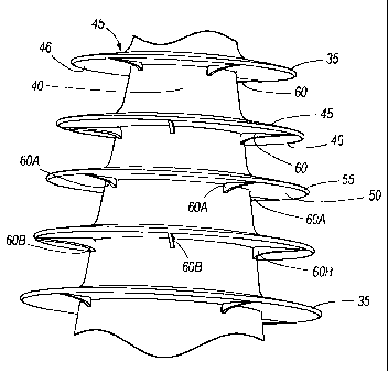
[0011] Figs. 1 through 4 illustrate an exemplary cable termination 10
operable to support
a high-voltage cable 11 therethrough and to connect the high-voltage cable 11
to ground 14
(schematically shown in Fig. 3). In the illustrated construction, the cable
termination 10 is
defined by a substantially elongated tubular body 12 extending along a center
axis 65 (Fig.
3). The cable termination 10 includes a first end 17, and second end 22 and a
through
aperture 19 extending between the first end 17 and the second end 22. The
cable termination
also includes a first portion 15 adjacent to the first end 17. The first end
17 has a first
diameter. The cable termination also has a second portion 20 adjacent to the
second end 22.
The second end 22 has a second diameter. In the illustrated construction, the
second diameter
is greater than the first diameter. However, other constructions of the cable
termination 10
can include a tubular body with a constant diameter or alternatively more than
two portions
with different diameters. The cable termination 10 also includes a number of
sheds 35
extending from the tubular body 12, which are described in more detail below.

CA 02694813 2012-09-07
WO 2009/020461 PCT/US2007/075486
3
[0012] As indicated above, the cable termination 10 is operable to support
a high-voltage
cable 11 extending therethrough, where the second end 22 of the cable
termination 10 is
adjacent to the ground 14. Accordingly, the first end 17 of the cable
termination 10 can be
defined as the high-voltage end and a second end 22 can be defined as the
ground or
connecting end of the cable termination 10. Moreover, the longitudinal
distance on the
surface of the cable termination 10 and between the first end 17 and the
second end 22 can be
defined as the creepage distance. For the purposes of this application,
"creepage" is defined
as the electrical leakage on a solid dielectric surface (e.g., the surface of
the cable termination
10). Accordingly, the "creepage distance" is the shortest distance on the
dielectric surface
between two conductive elements (e.g., high-voltage cable 11 and the ground
14), where
current tracks or crawls across a generally non-conductive element between two
conductive
elements.
[0013] The dimensions of the cable termination 10 are at least in part
based on the
voltage rating of the cable extending through the cable termination 10 (e.g.,
cable 11 in Fig.
3). For example, the longitudinal distance between the first end 17 and the
second end 22 can
be calculated or determined based on the voltage rating of the cable supported
by the cable
termination 10. In one embodiment of the invention, the cable termination 10
is designed to
support a cable with a voltage rating generally between 69 kV and 800 kV. For
a voltage
rating of 130 kV, the longitudinal distance between the first end 17 and the
second end 22 of
the cable termination is about 8 ft.
[0014] In the embodiments shown in Figs. 1 and 4, a number of sheds 35
extend radially
from an outer surface 40 of the tubular body 12. In the illustrated
construction, the
longitudinal distance between any two sheds 35 is substantially constant. Each
shed 35 is
defined by a substantially flat plate in a ring-like form including a top
surface 45 and a
bottom surface 46. The top and bottom surfaces 45, 46 of each shed 35 are
defined between
an inner edge 50 and an outer edge 55 of the ring-like plate. The diameter of
the inner edge
50 is dependent on the portion of the cable termination 10 from which the shed
35 extends.
For example, a shed 35 extending from the second portion 20 includes an inner
edge 50 with
a larger diameter than a shed 35 extending from the first portion 15. However,
the radial
distance between the inner edge 50 and the outer edge 55 is substantially
equal for every shed
35 of the cable termination 10. In the illustrated construction, the inner
edge 50 and the outer

CA 02694813 2010-01-27
WO 2009/020461 PCT/US2007/075486
- 4 -
edge 55 define an annulus. However, the inner edge 50 and outer edge 55 can
define
different shapes in other constructions of the cable termination 10.
[0015] With reference to Fig. 4, the cable termination 10 also includes a
set of four
supports 60 integrally molded with each shed 35 (only three supports 60 for
each shed 35 are
shown in Fig. 4). Each support 60 includes a rib extending from the outer
surface 40 of the
cable termination 10 to the outer edge 55 of the shed 35. The four supports 60
corresponding
to a shed 35 are separated from one another by a 90 degree angle.
Additionally, the ribs of
supports 60 coupled to one shed 35 (for example, supports 60A) are offset with
respect to the
ribs of supports 60 coupled to an immediately adjacent shed 35 (for example,
supports 60B)
by a 45 degree angle. The ribs of each support 60 are substantially
perpendicular to a center
axis 65 (shown in Fig. 3) of the cable termination 10. Other constructions of
the cable
termination 10 can include a different number of supports 60 coupled to each
shed 35 as well
as a different angular separation between each support 60. For example, two
supports 60 can
be separated by an angle between about 45 and about 180 degrees. The supports
60 can also
include a shape different than the one illustrated in Fig. 4. Also, supports
60 of one shed 35
can be off-set with supports 60 of another shed 35 by an angle between about 0
and about 180
degrees.
[0016] With reference to Fig. 3, the through aperture 19 of the cable
termination 10
includes a first part 70 aligned with the axis 65 and includes a first
diameter d. The through
aperture 19 also includes a second part 75 that is also aligned with the axis
65 and includes a
second diameter D. In the illustrated construction, the diameter D of the
second part 75 is
greater than diameter d of the first part 70. When the cable termination 10
and the high-
voltage cable 11 are assembled, the cable 11 snugly fits through the first
part 70 of the
through aperture 19. A space 77 is formed between the outer surface of the
cable 11 and the
inner surface of the second part 75 of the through aperture 19. In some
constructions, the
space 77 at least partially surrounds a connection or support element (not
shown) of the high-
voltage cable 11.
[0017] Still with reference to Fig. 3, the illustrated construction of the
cable termination
includes a primary or main portion 80 and a secondary or inner portion 85
integrally
formed with the primary portion 80 and adjacent to the second end 22 of the
cable
termination 10. The main portion 80 of the cable termination 10 is
manufactured of a silicon
rubber material and includes the sheds 35. The inner portion 85 of the cable
termination 10

CA 02694813 2010-01-27
WO 2009/020461 PCT/US2007/075486
- 5 -
includes a molded rubber electrode. The molded rubber electrode of the inner
portion 85 can
be a silicon-based material with semiconductive properties. Other
constructions of the cable
termination 10 can include one or more portions of silicon rubber material
with additives that
provide the one or more portions with conductive properties based on desired
parameters of
the cable termination 10.
material is that the silicon rubber material provides the cable termination 10
with a self-
cleaning feature. More specifically, the cable termination 10 can deform in a
manner such
that dirt, debris and other undesired elements are cleaned from the sheds 35
by natural agents
(e.g., wind and rain). In addition, forming the sheds 35 with the silicon
rubber material and
providing the sheds 35 with the supports 60 allows the sheds 35 to deform such
that the self-
cleaning can occur but contact of the sheds 35 with one another is prevented
or reduced.
[0019] Another advantage of manufacturing the cable termination 10 with
silicon rubber
material and forming supports 60 is that the supports 60 allow the use of less
material in the
manufacturing of the cable termination 10 which reduces costs. As a
consequence, the cable
termination 10 can include a relatively low number of sheds 35 and the sheds
35 can include
a thinner annulus. The use of less silicon rubber material and the cable
termination 10
including a lesser number of sheds 35 results in the cable termination 10
providing a longer
creepage distance, thus improving the performance of the cable termination 10.
[0020] Various features and advantages of the invention are set forth in
the following
claims.

Representative Drawing
A single figure which represents the drawing illustrating the invention.
Administrative Status

2024-08-01:As part of the Next Generation Patents (NGP) transition, the Canadian Patents Database (CPD) now contains a more detailed Event History, which replicates the Event Log of our new back-office solution.

Please note that "Inactive:" events refers to events no longer in use in our new back-office solution.

For a clearer understanding of the status of the application/patent presented on this page, the site Disclaimer , as well as the definitions for Patent , Event History , Maintenance Fee  and Payment History  should be consulted.

Event History

Description Date
Common Representative Appointed 2019-10-30
Grant by Issuance 2013-09-24
Inactive: Cover page published 2013-09-23
Inactive: Final fee received 2013-07-02
Pre-grant 2013-07-02
Notice of Allowance is Issued 2013-04-08
Letter Sent 2013-04-08
4 2013-04-08
Notice of Allowance is Issued 2013-04-08
Inactive: Approved for allowance (AFA) 2012-12-31
Amendment Received - Voluntary Amendment 2012-09-07
Inactive: S.30(2) Rules - Examiner requisition 2012-03-08
Inactive: IPC assigned 2012-01-31
Amendment Received - Voluntary Amendment 2011-08-08
Inactive: IPC removed 2010-09-23
Inactive: First IPC assigned 2010-09-23
Letter Sent 2010-09-07
Request for Examination Requirements Determined Compliant 2010-08-24
All Requirements for Examination Determined Compliant 2010-08-24
Request for Examination Received 2010-08-24
Letter Sent 2010-06-07
Inactive: Office letter 2010-06-07
Inactive: Single transfer 2010-04-23
Inactive: Declaration of entitlement - PCT 2010-04-23
Inactive: Cover page published 2010-04-16
Inactive: First IPC assigned 2010-03-29
IInactive: Courtesy letter - PCT 2010-03-29
Inactive: Notice - National entry - No RFE 2010-03-29
Inactive: IPC assigned 2010-03-29
Application Received - PCT 2010-03-29
National Entry Requirements Determined Compliant 2010-01-27
Application Published (Open to Public Inspection) 2009-02-12

Abandonment History

There is no abandonment history.

Maintenance Fee

The last payment was received on 2013-07-23

Note : If the full payment has not been received on or before the date indicated, a further fee may be required which may be one of the following

  • the reinstatement fee;
  • the late payment fee; or
  • additional fee to reverse deemed expiry.

Patent fees are adjusted on the 1st of January every year. The amounts above are the current amounts if received by December 31 of the current year.
Please refer to the CIPO Patent Fees web page to see all current fee amounts.

Owners on Record

Note: Records showing the ownership history in alphabetical order.

Current Owners on Record
G & W ELECTRIC COMPANY
Past Owners on Record
MINGYANG ZHOU
Past Owners that do not appear in the "Owners on Record" listing will appear in other documentation within the application.
Documents

To view selected files, please enter reCAPTCHA code :


To view images, click a link in the Document Description column (Temporarily unavailable). To download the documents, select one or more checkboxes in the first column and then click the "Download Selected in PDF format (Zip Archive)" or the "Download Selected as Single PDF" button.

List of published and non-published patent-specific documents on the CPD .

If you have any difficulty accessing content, you can call the Client Service Centre at 1-866-997-1936 or send them an e-mail at CIPO Client Service Centre.


Document
Description 
Date
(yyyy-mm-dd) 
Number of pages   Size of Image (KB) 
Abstract 2010-01-26 1 58
Representative drawing 2010-01-26 1 13
Description 2010-01-26 5 255
Drawings 2010-01-26 4 64
Claims 2010-01-26 4 129
Cover Page 2010-04-15 1 38
Claims 2012-09-06 3 108
Description 2012-09-06 5 253
Representative drawing 2013-08-28 1 12
Cover Page 2013-08-28 1 39
Notice of National Entry 2010-03-28 1 197
Courtesy - Certificate of registration (related document(s)) 2010-06-06 1 125
Acknowledgement of Request for Examination 2010-09-06 1 179
Commissioner's Notice - Application Found Allowable 2013-04-07 1 164
PCT 2010-01-26 3 115
Correspondence 2010-03-28 1 19
Correspondence 2010-04-22 3 69
Correspondence 2010-06-06 1 15
PCT 2010-06-28 1 48
Fees 2011-07-26 1 203
Correspondence 2013-07-01 1 44