Note: Descriptions are shown in the official language in which they were submitted.
CA 02694918 2010-01-28
WO 2009/019231 PCT/EP2008/060177
Diagnostic method for an internal combustion engine through
analysis of its exhaust gases and a device for implementing same
[0001] The present invention relates to a diagnostic method
for an internal combustion engine through analysis of its exhaust
gases and a device for implementing said method.
[0002] It relates more particularly to the analysis of the
combustion of Diesel engines, in particular in order to diagnose
the efficiency of the pollution control system connected to this
type of engine.
[0003] Indeed, the fight against pollution, regardless of its
origin, is at the center of international discussions today. All
land vehicles, including the automobile, are partially
responsible. Governments and manufacturers have therefore been
working for years to limit the polluting emissions of these
vehicles. The measures taken have gone in the direction of a
tightening of anti-pollution standards in the years to come.
[0004] While vehicles equipped with spark ignition engines
(gasoline, GPL (liquefied petroleum gas), GNV (natural gas for
vehicles) and E85 engines) are relatively easy to clean using
catalysts, Diesel engines are much less so. The particles emitted
by this type of engine do not pose any particular problems,
insofar as very effective filters are available on the market and
equip a growing number of Diesel vehicles.
[0005] The reduction of nitrogen oxides (NOX), however, is
much more delicate, due to the fact that the pollution control
systems used, generally EGR (Exhaust Gas Recirculation) valves,
work depending on many related variables which may drift. This
drift, often difficult to diagnose, creates problematic
malfunctions impacting the proper pollution control of the
engine, in particular.
CA 02694918 2010-01-28
WO 2009/019231 PCT/EP2008/060177
2
[0006] More precisely, as one knows, a Diesel engine works in
surplus air mode, therefore in the presence of a large amount of
oxygen, which chemically causes strong emissions of nitrogen
oxides (NOx). Through the EGR valve, exhaust gases are re-
injected into the intake, thereby delaying the flash point, and
thereby reducing the formation of NOx. The EGR valve is driven by
a computer from idle to approximately 3000 rpm, depending on
various parameters.
[0007] The combustion of a Diesel engine, as perfect as it may
be, creates soot in addition to particles. This soot causes a
sooting up of the EGR valve and the intake manifold at variable
mileages. Any geometric modification of the intake manifold
(narrowing of the conduits due to sooting) will cause a
malfunction for lack of air filling. The performance and power of
the engine will be greatly affected.
[0008] The exhaust line and the pollution control system will
also clog, intensifying the engine malfunctions. When the
pollution control system becomes inoperative, the computer
controls the EGR valve in the closed position, but also reduces
the engine performance by limiting the supercharging pressure.
[0009] Although a number of methods exist which make it
possible to determine whether an engine's exhaust gases exceed
the prescribed admissible atmospheric pollution values, such as,
for example, that described in patent application BE 84 46 22
which proposes, in particular, analyzing the engine's exhaust
gases in order to determine whether, for different prescribed
control modes, their levels exceed the stipulated admissible
atmospheric pollution values in carbon monoxide (CO) and
hydrocarbon (HC).
[0010] Furthermore, devices and methods for engine control,
e.g. for determining the amount of exhaust gases to be re-
introduced to the engine's combustion air, are known. For
example, US 2002/157458 describe a method to measure carbon
dioxide in the recirculated air of an engine's precombustion.
US6457461 disclose a system and a method for diagnosing a
component failure in an internal combustion engine to divert
CA 02694918 2010-01-28
WO 2009/019231 PCT/EP2008/060177
3
exhaust gas from the engine exhaust to the engine intake.
Whereas, US 2003/191575 describe a system and a method for
estimating NOx content of exhaust gas produced by an internal
combustion engine to determine the correct proportions of air,
fuel and exhaust gas to control the engine, EGR system and/or
turbocharger.
[0011] On the other hand, DE 10 2005013936 discloses
measurements of carbon dioxide levels to monitor the normal or
sufficient regeneration of a Diesel engine particle filter in an
exhaust line.
[0012] Currently, in Diesel engine maintenance or repair, to
diagnose malfunctions on the engine, it is well known to measure
smoke emission. However, the smoke-opacity test do not allow to
diagnose precisely which part of the engine, or device
associated, is defective.
[0013] There is currently no method allowing precisely and
simply to diagnose malfunctions negatively impacting the degree
of pollution of the exhaust gases from a Diesel engine.
[0014] The present invention discloses a method and a device
to diagnose malfunctions on the engine in Diesel engine
maintenance or repair.
[0015] Furthermore, it discloses a method to determine whether
the Diesel engine, or at least one device associated with it, is
affected by a malfunction of a nature, for instance, to alter the
engine's performance, cause a breakdown of the engine or to
determine whether the device is defective.
[0016] It proposes, in general, a diagnostic method for a
Diesel engine to determine whether the engine, or at least one
device associated therewith, is affected by one or several
malfunctions negatively influencing the degree of pollution of
the exhaust gases produced by this engine. The pollution control
system will be likewise affected.
[0017] The diagnostic method according the present invention
comprises the steps of analysing the level of a first exhaust
gas, or the evolution of the first exhaust gas level, according
to a predetermined state of said engine, and deducing or
CA 02694918 2010-01-28
WO 2009/019231 PCT/EP2008/060177
4
characterizing, from said analysis, any malfunction
affecting the engine and/or the device connected thereto.
[0018] The predetermined state of the engine has to be
understood as being any suitable engine speed.
[0019] The inventors indeed noticed that from the analysis of
an exhaust gas of Diesel engines allow to precisely characterize
the principal malfunctions affecting the pollution control system
of a the engine, and more generally, a good number of
malfunctions affecting the Diesel engine, or at least one device
associated therewith, and in particular having a direct impact on
the pollution level of this engine.
[0020] According to particular embodiments, the method may
comprise one or a combination of any of the following
characteristics:
- the level or evolution of the first exhaust gas is analyzed in
combination with the level, or evolution of the level, of at
least another exhaust gas,
- the first exhaust gas and the at least another exhaust gas are
selected from the group consisting in carbon dioxide (C02),
carbon monoxide (CO), oxygen (02), nitrogen oxides (N0X), and
unburnt hydrocarbons (HC),
- the level and the evolution of the level of the gases selected
from the group consisting in carbon dioxide (CO2), carbon
monoxide (CO), oxygen (02), nitrogen oxides (N0X) and unburnt
hydrocarbons (HC), are analysed depending on several
predetermined states, and, from said analysis, the malfunctions,
which may be affecting the engine and/or the device connected
thereto, are deduced or characterized,
- according to a predetermined operating state of the engine, the
level of the first exhaust gas, alone or in combination with at
least another exhaust gas, is measured and compared to a first
level of said exhaust gas measured for a state representing a
normal operation of said engine or the device connected thereto,
and/or compared to a second level of said exhaust gas measured
for a state representing a abnormal operation of said engine, or
the device connected thereto, and characterizing a predetermined
CA 02694918 2010-01-28
WO 2009/019231 PCT/EP2008/060177
malfunction, and from said comparison, deducing that said
engine, or said device connected thereto, is affected by said
predetermined malfunction,
- the predetermined state of the engine is idle, off after being
5 idle, start-up, idle after being started-up, 1200 rpm, between
around 3000 and around 3500 rpm, full load, idle after being
full-loaded
[0021] According to other preferred embodiments, preferably
taken in combination:
- the method comprises the steps of:
= analyzing the evolution of the level of carbon dioxide
according to an operating state of the engine causing the opening
of an exhaust gas recirculation (EGR) valve connected to said
engine, using a computer controlling the opening and closing of
said valve, and
= deducing, from a lack of increase of the level of carbon
dioxide after theoretical opening of the exhaust gas
recirculation valve, that said valve is not controlled by the
computer or blocked in the closed position,
or the steps of:
= analyzing the evolution of the carbon dioxide level
according to an operating state of said engine causing the
closing of an exhaust gas recirculation valve connected to said
engine using a computer controlling the opening and closing of
this valve, and
= deducing, from a lack of decrease, for an engine speed
between 3000 and 3500 rpm, of the carbon dioxide level after
theoretical closing of the exhaust gas recycling valve, that said
valve is blocked in the open position,
or the steps of:
= analyzing the evolution of the carbon dioxide level, for
an engine operation at a speed below 2700 rpm and at a speed
between 3000 and 3500 rpm, and
= deducing from a carbon dioxide level for said 3000 and
3500 rpm speed equal to, or higher than, the value measured for
a speed less than 2700 rpm, that said valve lacks sealing,
CA 02694918 2010-01-28
WO 2009/019231 PCT/EP2008/060177
6
- the method comprises the steps of:
= analyzing the carbon dioxide level and oxygen level,
engine off after an idle operation, and
= deducing that the exhaust line connected to said engine is
clogged, if, at the end of approximately 40 seconds, the carbon
dioxide level has not dropped to a value below approximately 1%
and the oxygen level is not higher than or equal to
approximately 20%,
- the method comprises the steps of:
= analyzing the carbon dioxide level and the oxygen level
for a fully loaded engine operation, and
= deducing, from a total carbon dioxide and oxygen level
less than approximately 19%, that the engine has insufficient air
filling,
- the method comprises the steps of:
= analyzing the carbon dioxide level for a fully loaded
engine operation, and
= deducing, from a decrease in the carbon dioxide level
during the fully loaded operation, that a common rail injector
system connected to said engine is affected by an internal leak,
or
= deducing, from a carbon dioxide level dropping by
approximately 1% to approximately 5% between the beginning and
the end of a fully loaded phase lasting approximately 15 seconds,
that a common rail injector system connected to the said engine
is affected by an internal leak,
or the steps of:
= analyzing, the evolution of the carbon monoxide level for
an idle operation of the engine and at a speed higher than, or
equal to, 1200 rpm, and
= deducing, from an increase in the carbon monoxide level
relative to the idle phase, that a common rail injector system
connected to said engine has an internal leak,
- the method comprises the steps of:
= analyzing the carbon dioxide level for a fully loaded
operation of the engine, and
CA 02694918 2010-01-28
WO 2009/019231 PCT/EP2008/060177
7
= deducing, from an increase of the carbon dioxide
level during fully loaded operation, that the flow regulator
connected to a high pressure pump of a common rail injection
system equipping said engine is defective,
or the steps of:
= analyzing either the evolution of the level of carbon
dioxide, from ignition of the engine until a stabilized idle
speed of said engine without exhaust gas recirculation, or the
level of carbon dioxide for a fully loaded operation of said
engine, and
= deducing, from an increase in the carbon dioxide level not
exceeding approximately 4 seconds and not exceeding approximately
1.5%, that the high pressure pump of the fuel injection system
equipping said engine is defective, or from an increase in the
carbon dioxide level exceeding 2.5% that the distributor-type
pump of said fuel injection system is defective,
- the method comprises the steps of:
= analyzing the carbon dioxide level and the oxygen level
for a fully loaded engine operation, and
= deducing, from a total level of carbon dioxide and oxygen
less than approximately 19%, with a carbon dioxide level higher
than approximately 8%, and an oxygen level lower than
approximately 10%, that the turbocharger equipping said engine is
defective,
or the steps of:
= analyzing the evolution of the concentration of unburnt
hydrocarbons for a speed increase or a return to idle thereof,
and
= deducing, from an increase in the level of hydrocarbons
for the increase in speed, and a concentration higher than
approximately 40 ppm after returning to idle, that the
turbocharger equipping said engine has an oil leak on at least
one of its bearings,
- the method comprises the steps of:
= analyzing the carbon monoxide level and the unburnt
hydrocarbons level, and
CA 02694918 2010-01-28
WO 2009/019231 PCT/EP2008/060177
8
= deducing, from a carbon monoxide level higher than
approximately 0.05% and a hydrocarbon level higher than
approximately 10 ppm, that a poor spraying of the injectors is
affecting said engine,
or the steps of :
= analyzing the level of nitrogen oxides, either for an idle
operation of the engine with exhaust gas recirculation, or for a
fully loaded operation, and
= deducing, for a direct injection Diesel engine, from a
level of nitrogen oxides higher than approximately 120 ppm at
idle operation, or higher than approximately 250 ppm at fully
loaded operation, that a poor spraying of the injectors is
affecting said engine
- the method comprises the steps of:
= analyzing, the level of carbon monoxide and the level of
nitrogen oxides for an idle operation of the engine, or at a
speed of approximately 3000 rpm, and
= deducing:
a) from a carbon monoxide level lower than 0.005% and a
nitrogen oxide level higher than approximately 140 ppm for a
direct injection engine operating at idle with exhaust gas
recirculation, that said engine has an injection advance excess;
or
b) from a carbon monoxide level lower than approximately
0.005% and a nitrogen oxide level higher than approximately 90
ppm for an indirect injection engine operating at idle, with
exhaust gas recirculation, that said engine has an injection
advance excess; or
c) from a carbon monoxide level higher than 0.02% and a
nitrogen oxide level lower than 90 ppm for a direct injection
engine operating idle, that said engine lacks injection advance;
or
d) from a carbon monoxide level higher than 0.02% and a
nitrogen oxide level higher than 100 ppm for a direct injection
engine operating at a speed of approximately 3000 rpm, that said
engine lacks injection advance; or
CA 02694918 2010-01-28
WO 2009/019231 PCT/EP2008/060177
9
e) from a carbon monoxide level higher than 0.02% and a
nitrogen oxygen level lower than 60 ppm for a direct injection
engine operating at idle, that said engine lacks injection
advance; or
f) from a carbon monoxide level higher than 0.02% and a
nitrogen oxide level higher than 60 ppm for a direct injection
engine operating at approximately 3000 rpm, that said engine
lacks injection advance,
- the method comprises the steps of:
= analyzing the evolution of the carbon monoxide level and
the nitrogen oxygen levels over a speed increase of the engine,
from idle to approximately 1200 rpm, and
= deducing, from a decrease in the level of nitrogen oxides
without variation of the carbon monoxide level, that the intake
circuit equipping said engine has an air scoop,
- the method comprises the steps of:
= analyzing the level of unburnt hydrocarbons (HC) for an
engine operating at idle, and
= deducing from a level higher than 100 ppm that the
engine's injection circuit is affected by a seizing of the
injectors,
[0022] The present invention also relates to a device for
diagnosing a Diesel engine to determine whether said engine, or
at least one device connected thereto, is affected by at least
one malfunction negatively influencing the degree of pollution of
the exhaust gases produced by said engine, comprising means for
measuring at least a first exhaust gas selected from the group
consisting in carbon dioxide (COz), carbon monoxide (CO), oxygen
(02), nitrogen oxides (N0X), and unburnt hydrocarbons (HC) or a
combination thereof, means for analyzing the level of said gas,
or the evolution of said level, according to one or several
predetermined states of said engine, and processing means capable
to characterize, from said analysis, any malfunction(s) affecting
said engine and/or the devices connected thereto
CA 02694918 2010-01-28
WO 2009/019231 PCT/EP2008/060177
[0023] According to particular embodiments, the
diagnostic device may comprise one or a combination of any of the
following characteristics:
- the analysis means comprise at least one gas detector in the
5 form of a measuring cell,
- the predetermined state of the engine is idle, off after being
idle, start-up, idle after being started-up, 1200 rpm, between
around 3000 and around 3500 rpm, full load, idle after being
full-loaded.
10 [0024] The present invention relates also to a computer
program executable on the device, according to the present
invention, containing instructions that, when executed, perform
the method steps of the method according to the present
invention.
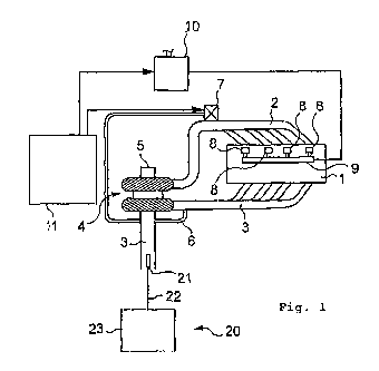
[0025] The Diesel engine, for which a diagnostic is
established using the diagnostic device according to the present
invention, is illustrated in figure 1. It is, in a known manner,
a Diesel internal combustion engine 1, for example for a car, a
truck, a tractor, or a boat. In figure 1, the engine uses direct
injection, which comprises, on the intake side, a supercharging
air supply circuit 2 and, on the exhaust side, an exhaust gas
conduit 3. In another embodiment, the Diesel engine may be of the
indirect injection type.
[0026] The exhaust gases in the exhaust gas conduit 3 drive a
turbocharger 4 provided with an atmospheric air inlet 5.
[0027] These exhaust gases can be processed through a catalyst
and a particle filter, not shown in the figure, then discharged
into the environment.
[0028] Also provided is an exhaust gas recirculation device
comprising a bleed line for bleeding of exhaust gases on the
exhaust gas conduit 3 and an EGR valve 7 controlling the
admission of these exhaust gases bled through the line 6 in the
intake circuit, i.e. here the supercharging air supply circuit 2.
[0029] The Diesel engine is also supplied with fuel (diesel
oil) through injectors 8, themselves supplied, by a common rail 9
connected to a high-pressure injection pump 10.
CA 02694918 2010-01-28
WO 2009/019231 PCT/EP2008/060177
11
[0030] In another embodiment, the Diesel internal
combustion engine may not comprise a turbocharger. Moreover, the
common rail 9 and the high-pressure injection pump 10 may be
replaced by a distributor-type fuel injection pump.
[0031] An electronic control center 11 is also provided to
control, in particular, the EGR valve 7 and the high-pressure
injection pump 10.
[0032] The diagnostic device 20, according to the present
invention, comprises a multi-gas analyzer 21 protected by a
filtration system. In practice, this is a five-gas analyzer
equipped with several gas detectors present in the form of an
optical bench detecting hydrocarbons (HC), carbon monoxide (CO)
carbon dioxide (COz), and oxygen and nitrogen oxide detection
cells, for example of the type marketed by the company City
Technology, able to measure gas levels.
[0033] More precisely, the gases detected by these cells and
this bench are carbon dioxide (COz), carbon monoxide (CO), oxygen
(02), nitrogen oxide (NOx) and unburnt hydrocarbons (such as
hexane and propane, for example).
[0034] The collection tube 22 of the analyzer is introduced
into the exhaust line; however, in another embodiment the
analysis may be done at the outlet of the line. It is also
possible to implement a system comprising detectors coupled to
means for analyzing signals emitted by gas detectors, in order to
calculate the respective gas levels.
[0035] The multi-gas detector 21 is functionally connected by
the measurement tube 22 to means 23 for interpreting the various
measured values. The means 23 comprise signal processing
electronics allowing in particular a phasing of the values, and a
traditional microcomputer, comprising a central processing unit,
random access memory (RAM) and read only memory (ROM), and
input/output units interconnected by buses as well as a power
supply.
[0036] Means for displaying the results of the diagnostic are
also provided with the device 20 here.
CA 02694918 2010-01-28
WO 2009/019231 PCT/EP2008/060177
12
[0037] The microcomputer is a diagnostic apparatus
specially dedicated to the implementation of the diagnostic
method according to the present invention. In another embodiment,
it may be a microcomputer of a diagnostic apparatus for a more
general internal combustion engine or the microcomputer of a
personal computer (PC).
[0038] Printing means may be connected to the apparatus, to
print the report, or reports, related to the diagnostic,
preferably maintenance sheets indicating the checks and repairs
to be performed.
[0039] The algorithms (modeled defaults) used for the
implementation of the diagnostic method according to the present
invention are thus present in the form of at least one program
transferred into the microcomputer to interpret the various
measured values.
[0040] The diagnostic method is present, in a preferred
embodiment, in the form of the protocol which will now be
described in more detail as a complement to table 1, which makes
it possible to diagnose the effectiveness of the pollution
control system associated with the Diesel engine described in
support of figure 1.
[0041] The protocol makes it possible to sweep the entire
working range of the engine's operation by checking all steps of
combustion with their related chemical transformation. It makes
it possible in particular to very precisely diagnose the
malfunctions of the engine or devices associated with the engine
which are the causes of the malfunction of this engine's
pollution control system.
[0042] Before launching the measurement and diagnostic method,
the protocol asks the user to specify the type of Diesel engine
on which the diagnostic is being performed (injection mode,
turbocharger present or not...).
[0043] Preferably, the measurement is done every 500 ms.
[0044] The diagnostic device 20 according to the present
invention, implementing the diagnostic method described, is
CA 02694918 2010-01-28
WO 2009/019231 PCT/EP2008/060177
13
present in the form of an independent apparatus able to
be incorporated, in order to perform load measurements.
[0045] It should be noted in this respect that the gas levels
are expressed, in the framework of the present invention, either
in percentages, or in ppm (mg/1).
[0046] The dynamic diagnostic method according to the
invention is implemented with the device according to the
protocol which will now be described as a complement to table 1
below. It is preferably implemented on a hot Diesel engine.
[0047] 1. First idle
During this phase, the level of unburnt hydrocarbons (HC) is
measured. Indeed, a hydrocarbon (HC) level higher than 100 ppm at
idle is the sign of a significant problem with the injection
circuit corresponding to a seizing of the injectors. In this
case, the protocol will not be able to continue and the
diagnostic device will display the observed anomaly. It will then
be necessary to check the injectors and the diesel oil circuit.
The tube introduction test makes allow to determine whether the
tube was indeed introduced into the exhaust line.
[0048] 2. Cutting the engine
The duration of this phase is variable depending on the level of
carbon dioxide (COz): initially planned to last 50 seconds, it
may extend itself 60 seconds longer if the value of this gas is
too high to detect and analyze the increase of the carbon dioxide
(CO2) during starting-up of the engine, in the following step.
[0049] 3. Starting up of the engine with maintenance at idle
During this phase, the proper operation of the EGR valve and of
the pump and injectors is analyzed. What is check is the:
- operation of the control of the EGR valve (command in
closed position) by the computer;
- operation of the EGR valve through the carbon dioxide
(CO2) value, the level of which must increase with its opening.
- operation of the EGR valve through the nitrogen oxide
(NOx) value, the level of which must drop consecutively to its
opening;
CA 02694918 2010-01-28
WO 2009/019231 PCT/EP2008/060177
14
- level of gas recirculated through the carbon
dioxide (CO2) value;
- increase in pressure of the diesel oil circuit through the
increase time of the carbon dioxide (C02) value (increased
pressure of the pump);
- spraying of the injectors through the carbon monoxide
(CO), hydrocarbon (HC) and nitrogen oxide (NOx) values;
- injection point through the carbon monoxide (CO) and
nitrogen oxide (NOx) values;
- the compression of the engine (general condition of the
mechanics) through the hydrocarbon (HC) and carbon monoxide (CO)
values;
- air filling coefficient of the engine through the
combination of the carbon dioxide (CO2) and oxygen (02) values.
The carbon dioxide (C02) level, after starting up of the engine,
must quickly reach 1.7% to 2.7%, which means that the quantity of
diesel oil injected is correct. Then it must increase
proportionally to the opening of the EGR valve without exceeding
a value of 5.6%.
[0050] 4. Engine at 12000 rpm
At this speed, there is balancing of the manifold pressure with
the atmospheric pressure. This enables the detection of any air
scoop on the intake circuit. To highlight this malfunction, one
takes the nitrogen oxide (NOx) and carbon monoxide (CO) levels
into account: the nitrogen oxide (NOx) value must drop
significantly and the carbon monoxide (CO) value remains the
same, relative to the idle speed.
[0051] 5. Engine at an engine speed between 3000 and 3500 rpm
Over this range of speeds, the EGR valve must be closed. During
this phase, what is check is the:
- closing of the EGR valve through the decrease of the
carbon dioxide (C02) value;
- sealing of the EGR valve through the carbon dioxide (CO2)
level;
- sealing of the main turbocharger bearings through the
hydrocarbon (HC) value;
CA 02694918 2010-01-28
WO 2009/019231 PCT/EP2008/060177
- the closed EGR valve filling coefficient through the
combination of the carbon dioxide (CO2) and oxygen (02) levels;
- the injection timing through the carbon monoxide (CO) and
nitrogen oxide (N0x) values.
5 [0052] 6. Fully loaded engine
This test is done with accelerator wide open at the maximum
governing speed. During this phase, what is check is:
- internal leaks of the injectors through the carbon dioxide
(COz) value;
10 - the flow regulator on common rail systems through the
carbon dioxide (C02) level;
- operation of the turbocharger through the carbon dioxide
(COz) value;
- insufficient filling of the engine with oxygen, for
15 example due to clogging of the intake manifold, by taking the
combination of oxygen (02) and carbon dioxide (COz) into account;
- the flow of the high-pressure pump through the carbon
dioxide (COZ) value;
- the spraying of the injectors through the nitrogen oxide
(NOx) level.
[0053] 7. Return to idle
This phase makes allows to confirm the proper or improper
operation of the EGR valve as well as its control. One will also
be able to check the sealing of the main bearings of the
turbocharger.
[0054] 8. Cutting the engine
During this phase, any clogging of the exhaust line will be
highlighted through the carbon dioxide (COz) and oxygen (02)
values (the 02 level must quickly reach 20% and the carbon
dioxide (CO2) level must tend toward zero) In the event of
clogging of the exhaust line, the exhaust gas recirculation level
will be too high and will lead to a malfunction of the pollution
control circuit.
CA 02694918 2010-01-28
WO 2009/019231 PCT/EP2008/060177
16
TABLE 1
Engine Idle Engine Start-up Idle Around Between Fully Idle Engine
start- cut 1200 3000 loaded cut
up rpm and 350D
rpm
30e or 40s 30s 90s 15s 30s 90s
110s
Injecto
r
seizing
test
Test
on
c02
levels
Tube
intro-
duction
test
Exhaust
line
clogging
Poor
spraying
of
the
injectors
Internal
leaks
On
injectors
EGR
valve
deective
EGR EGR
valve valve
poorly poorly
controlled controlled
or or
neutralized neutralized
Leaks Leaks
On On
Main Main
Bearing bearing
of of
turbo- turbo-
cnarger charger
Turbo-
charger
defective
HP HP
pump Pump
defective defective
Flow
regulator
defective
Engine
Filling
problem
Air
scoop
on
intake
circuit
Flow Flow Flow
problem problem problem
Lack Lack
of Of
advance advance
Too Too
much Much
advance advance
CA 02694918 2010-01-28
WO 2009/019231 PCT/EP2008/060177
17
[0055] The test is thus described by a person at the
controls of the vehicle who follows the instructions provided by
the software during performance of the protocol.
[0056] The various malfunctions which may also be detected and
characterized using the present invention are described in more
detail below.
[0057] 1. EGR valve not controlled or neutralized
As indicated above, the EGR valve enables the recirculation of
part of the exhaust gases in the intake so as to limit the
presence of nitrogen oxides (NOx) . The checking method is based
on the carbon dioxide (CO2) value, which increase when the
computer commands the opening of the EGR valve. The carbon
dioxide (COz) value, EGR valve closed, at idle, is normally
between 1.6% and 2.7%. By admitting, for example, that one
recycles 100% of these values, then the carbon dioxide (CO2)
level should be within a range between 3.2% and 5.4%. If these
values are between 1.6% and 2.7%, on both idle phases of the
protocol, the EGR valve is not commanded by the computer, for
example due to a defective air flowmeter, or neutralized (blocked
in the closed position).
[0058] 2. Defective or non-sealing EGR valve
The EGR valve is commanded by the computer over speed ranges
taken into account by the protocol: toward 3000 rpm, in practice
between 2700 rpm and 3000 rpm, the computer closes the EGR valve
and therefore the recirculation of exhaust gases in the intake,
which normally creates a drop of the carbon dioxide level.
Moreover, if the EGR valve lacks sealing due to fouling, the
carbon dioxide (COZ) value will be equal to, or higher than, the
levels measured during the idle and 1200 rpm phases (at idle,
during opening of the EGR valve, the recirculated carbon dioxide
(CO2) value must not exceed the value of 5.8% and even,
preferably, 5.60). In this respect, significant clogging of the
exhaust line may be at the origin of the fouling of the EGR
valve.
CA 02694918 2010-01-28
WO 2009/019231 PCT/EP2008/060177
18
[0059] 3. Clogged exhaust line
The role of the exhaust line is crucial: the reduction of
decibels of the engine and the evacuation of burned gases. On
vehicles with pollution control, the exhaust line is equipped
with an oxidation pipe or a particle filter. These elements must
have a minimum of load loss to operate well. An engine problem,
driving a discharge of unburnt gases and soot and particles in
too large a quantity, will clog the exhaust line. Moreover, this
will cause an excess of recirculated exhaust gas in the intake
through the EGR, thereby increasing the initial malfunction and
causing a higher quantity of polluting gases to be discharged.
This has significant consequences for the operation of the engine
and its pollution control system. In extreme cases, it may
prevent the engine from starting up. It is during the last phase
of the protocol, engine cut, that the exhaust line is checked.
When the engine is stoped, the carbon dioxide (C02) values must
quickly fall to a value below 1% and the oxygen 02 value must,
likewise, exceed 20%. If these levels are not reached at the end
of 40 seconds, the exhaust line is considered to be clogged.
[0060] 4. Filling problem
Filling is the physical capacity of the engine to admit air. In a
Diesel engine, air compression enables the ignition of the diesel
oil through the elevation of the temperature in the cylinder. A
deficient quantity of air admitted into the engine causes the
following malfunctions:
- too long an ignition delay with, as consequences, a
formation of soot and particles;
- an increase in consumption with loss of power observed on
the road;
- smoke at the exhaust during acceleration;
The possible causes of a filling problem are:
- clogging of the exhaust line;
- clogging of the intake conduit;
- a non-sealing EGR valve;
- a defective turbocharger solenoid valve;
- a defective turbocharger;
CA 02694918 2010-01-28
WO 2009/019231 PCT/EP2008/060177
19
- incorrect clearance at the valves;
- wearing of the engine.
As the atmosphere is made up of approximately 20.9% oxygen (02)
per air contents, and taking the combustion of the hydrocarbons
(HC) into account upon combustion in the idle phase, the addition
of oxygen (02) and carbon dioxide (C02) levels must be at least
equal to 19% during the fully loaded phase. In the contrary case,
the engine has insufficient filling.
[0061] 5. Internal leak of the common rail injectors
The common rail injectors are generally of the electrohydraulic
type. On the hydraulic level, they are equipped with two chambers
(upper and lower) in which the balance or imbalance of pressure
allow to maintain the needle of the injector either in the closed
position, or in the open position. An internal circuit makes
allow to connect these two chambers and ensure the return of
diesel oil. When there is an internal leak on the injector
return, the quantity of fuel (pressure decrease) and the moment
of passage into the open position of the needle of the injector
are modified. This causes a lack of performance (correction of
the injection point and lack of flow). In the case of a
significant loss, this malfunction may even prevent the engine
from starting. Revealing internal leaks on the injectors is done:
- at 1200 and 3000 rpm through an increase in carbon
monoxide (C0) relative to the idle phase; or
- fully loaded, by a carbon dioxide (C02) level dropped by 1
to 5% between the beginning and the end of the phase.
The two analyses may, of course, be done to complement one
another.
[0062] 6. Checking the flow regulator of the high-pressure
(HP) pumps on the common rail systems
The common rail systems are equipped with a HP pump, the role of
which is to generate pressure according to the load and speed.
The quantity of diesel oil injected into the combustion chamber,
per cycle, depends on this pressure. The flow regulator serves to
inject the necessary and sufficient quantity of diesel oil, which
results in greatly limiting the temperature of the fuel at the
CA 02694918 2010-01-28
WO 2009/019231 PCT/EP2008/060177
level of the return circuit in the tank. When the flow
regulator is defective, the optimal quantity of diesel oil will
not be injected into the cylinders, which will result in
decreasing the engine's performance. Showing the malfunction of a
5 flow regulator is done at full load, when the pump provides
maximal pressure on its first two pistons. When the flow
regulator is hydraulically defective, the maximal pressure is not
immediately reached, and so the flow is not constant. This will
be translated in carbon dioxide (C02) level, connected to the
10 quantity of diesel oil injected and burned, showing an increase
in its values between the beginning and the end of the full load
phase. This increase of volume concentration (C02) must be higher
than 8% to validate the malfunction.
[0063] 7. Defective high pressure pump
15 The high pressure pump allow to generate a diesel oil pressure
depending on the engine speed and the load (in practice up to
1800 bars; 1 bar = 105 Pa). This pressure is variable according
to the types of pump and the systems used. One visualizes the
increase in pressure of the pump through the carbon dioxide (C0z)
20 slope upon start-up of the engine, but also at its maximal value
at idle (EGR valve closed). The carbon dioxide (CO2) increase
phase until stabilized idle must not exceed 4 seconds and its
value must exceed 1.6%, and even 1.7% in practice. During the
fully loaded phase, the pump must deliver at full flow on its
first two pistons. If this is defective, the carbon dioxide
(C02) value will not exceed 2.5%. On distributor-type fuel
injection pumps, although their operating principle is different,
the values will be identical.
[0064] 8. Poor spraying of the injectors
The quality of the spraying of the injectors is essential to
ensure optimal combustion of all of the diesel oil injected into
the combustion chamber. In the contrary case, the post combustion
will extend and generate an increase in the temperature with
significant formation of nitrogen oxides (NOx). There will also
be unburned elements in the form of residual hydrocarbons (HC)
and carbon monoxide (C0) ((HC) level higher than 10 ppm and CO
CA 02694918 2010-01-28
WO 2009/019231 PCT/EP2008/060177
21
value higher than 0.05%, regardless of the speed).
During improper spraying of the injectors, the level of nitrogen
oxides (NOx) will depend on the type of injection:
- direct injection: level higher than 120 ppm at idle (EGR
valve open) and value higher than 300 ppm fully loaded;
- indirect injection: level higher than 120 pm at idle (EGR
valve open) and value higher than 250 ppm fully loaded.
[0065] 9. Leaks on turbocharger main bearings
The turbocharger allows to increase the air filling of the
engine, and therefore its performance. This is a rotating machine
which uses the pressure from the exhaust gases to suck up and
compress the outside air admitted into the engine. The blade and
the axis of the turbocharger can exceed a speed of rotation of
150,000 rpm. At this speed, any lubrication flaws will cause the
destruction of the bearings and the turbocharger. Breaking of the
bearings causes the oil to be sucked up again and the engine to
race until it breaks. An oil leak on a turbocharger bearing is a
worrisome sign of wear. Upon leaks on the turbocharger bearings:
- at the speed of 3000 rpm, the level of hydrocarbons HC
will increase in relation to the values measured at idle and at
1200 rpm;
- similarly during the fully loaded phase, the level of
hydrocarbons HC will be higher than the values measured at 3000
rpm;
- upon return to idle, the level of hydrocarbons HC exceeds
the value of 40 ppm.
[0066] 10. Defective turbocharger
When the turbocharger is defective, due to a seized blade or a
cutting of the supercharging pressure, in particular, the filling
coefficient will drop significantly. At full load, the addition
of the oxygen (02) and carbon dioxide (C02) levels will then be
less than 19% with a carbon dioxide (C02) value higher than 8%
and an oxygen (02) level less than 10.5%.
[0067] 11. Injection advance excess
A diesel oil injection done too early causes too quick an
increase in pressure in the cylinder, characterized by engine
CA 02694918 2010-01-28
WO 2009/019231 PCT/EP2008/060177
22
rattles. On vehicles equipped with a distributor-type fuel
injection pump, blocking is necessary, but on common rail
systems, it is necessary to act on the origin of the malfunction
because there is no manual blocking action. An advance excess is
characterized by:
- direct injection values: At idle, EGR valve open, the
carbon monoxide (CO) levels are below 0.005% with nitrogen oxide
(NOX) values higher than 140 ppm.
- indirect injection values: At idle, EGR valve open, the
carbon monoxide (CO) values are below 0.005% with nitrogen oxide
(NOX) values higher than 90 ppm.
[0068] 12. Lack of injection advance
A lack of advance is characterized by a performance deficiency
due to a combustion still present during the descent of the
piston. The diesel oil injected therefore cannot burn correctly
because when the piston descends, the temperature drops. During a
lack of advance, the remarkable values of the gas will be:
- direct injection values:
at idle, the carbon monoxide (CO) levels are higher than
0.02% with nitrogen oxide (NOX) values less than 90 ppm;
. at a speed of approximately 3000 rpm, the carbon monoxide
(CO) levels are higher than 0.02% with nitrogen oxide (NOx)
values higher than 100 ppm.
- indirect injection values:
. at idle, the carbon monoxide (CO) levels are higher than
0.02% with nitrogen oxide (NOX) values less than 60 ppm.
. at a speed of approximately 3000 rpm, the carbon monoxide
(C0) levels are higher than 0.02% with nitrogen oxide (NOX)
values higher than 60 ppm.
[0069] 13. Air scoop on the intake circuit
When the engine turns at approximately 1200 rpm, there is
balancing of the manifold pressure with the atmospheric pressure.
This allows to detect any air scoop on the intake circuit. To
highlight this malfunction, the levels of nitrogen oxides (NOX)
and carbon monoxide (CO) are taken into account. In practice, the
nitrogen oxide (NOx) value should drop significantly and the
CA 02694918 2010-01-28
WO 2009/019231 PCT/EP2008/060177
23
carbon monoxide (CO) value should remain identical, in
relation to the idle speed.
[0070] 14. Flow problem
As indicated previously, the diesel oil flow is controlled by the
values of CO2 over the entire range of speeds. At idle, if the
CO2 value is less than 1.7% and this does not exceed 2.5% fully
loaded, a problem on the diesel oil flow is then proven. The CO2
value must be higher than 1% to continue the test.
[0071] The diagnostic method according to the present
invention implements a dynamic monitoring of the combustion of
the Diesel engine, in particular through the measurement of at
least one of (i) the concentration of each of two different gases
for a predetermined engine speed, (ii) the concentration of a
same gas at two different moments of a stabilized engine speed or
over each of two different ranges of engine speeds or for each of
two different states of a device connected to the engine, in
order to determine a state resulting from the sum of the volume
concentrations of two different gases or of a variation of
concentration of a same gas in order to establish the existence
of a given malfunction in case of drift relative to a reference
state.
[0072] According to this method, one analyzes at least the
volume concentration in carbon dioxide, and, preferably, also at
least one of the gases chosen from the group including carbon
monoxide (CO), oxygen (02), nitrogen oxides (NOX) and unburnt
hydrocarbons (HC) the five gases being very advantageously
analyzed to establish a complete diagnostic.
[0073] Of course, the present invention is not limited to the
embodiments described and illustrated.
[0074] In particular, the diagnostic device may, for example,
take the form of an incorporated system.