Note: Descriptions are shown in the official language in which they were submitted.
CA 02694921 2010-01-28
- 1 -
SAFETY CONSOLE
FIELD OF THE INVENTION
The present invention relates to a keyboard, in particular
a security keyboard with travel, for example, for the
secure input of a PIN with keystrokes.
BACKGROUND OF THE INVENTION
Keyboards, in particular keyboards for input of a PIN with
keystrokes, as they are conventionally manufactured
industrially at the present time, are usually constructed
from a keyboard conductor plate and movable keys. By
depressing the key a contact on the conductor plate is
closed and information can generated and/or forwarded.
Since confidential data can be involved the keyboard must
be protected against any tampering. For example, any
recording of the inputted PIN by an attacker must be
prevented.
In the case of keyboards with travel a possible attack
consists in disassembly of the keyboard, the subsequent
installation of a pressure-sensitive keyboard foil, and/or
making direct contact with the key contacts and recording
the PIN with the aid of evaluation electronics. Avoidance
of this kind of problem by the use of keyboards with no
travel that cannot be disassembled, such as touch screens,
for example, does not satisfy all keyboard users. In
particular a keyboard with travel is essential for blind
people, since here the actuation of a key can best be
achieved via the sense of touch.
A previous starting point to prevent any tampering with a
keyboard with travel is the installation of appropriate
housing switches; these are designed to prevent the
disassembly of the keyboard, in that they initiate an alarm
or the deletion of data in the event of interruption of
CA 02694921 2010-01-28
- 2 -
particular contacts that are, for example, arranged between
parts of the housing. However, an attacker can circumvent
this precautionary measure by removing just the keys and
installing evaluation electronics, without interrupting the
contacts in the housing that are located underneath the
keyboard. Here these contacts are designed to protect
individual parts of the keyboard from disassembly.
It can therefore be seen as an object of the present
invention to provide a keyboard, i. e. a security keyboard,
which enables the removal of a key, or the disassembly of
the keyboard, to be detected.
SUMMARY OF THE INVENTION
This object can be achieved by the subject of the present
invention according to the independent claims. Advantageous
forms of embodiments of the present invention are described
in the dependent claims.
In accordance with a first aspect of the present invention
a keyboard is described that has a key and a contact plate.
The contact plate has a first and a second contact
arrangement with in each case at least two electrically
conducting elements. To this end the key, when in a non-
actuated state, is configured to connect the conducting
elements of the first contact arrangement electrically with
one another, and not to connect the conducting elements of
the second contact arrangement electrically with one
another. Furthermore the key, when in an actuated state, is
configured to connect the conducting elements of the first
contact arrangement electrically with one another, and to
connect the conducting elements of the second contact
arrangement electrically with one another.
Expressed in other words in accordance with the first
dimension the idea of the present invention is based on a
two-level key function of the keyboard. The keyboard has at
least one key and one contact plate, for example, in the
CA 02694921 2010-01-28
- 3 -
form of a conductor plate. On the contact plate are located
two contact arrangements, with in each case at least two
electrically conducting contacts. The key can feature a
switching mat with two switching points. In the non-
actuated state the switching mat can have an initial
mechanical tension such that the switching mat already
makes contact with the contact plate. In this manner the
switching mat can close a (security) contact of one of the
two contact arrangements while still in the non-actuated
state. Thus any tampering, such as, for example, the
removal, or the absence, of the key, or the disassembly of
the keyboard, can be detected, and appropriate precautions
and security measures can be introduced as soon as the
security contact is interrupted, for example, in the event
of unauthorized removal of the key. A further function of
the keyboard is implemented by the actuation of the key: In
the depressed state the switching mat closes the contacts
of both contact arrangements on the contact plate and
information can be inputted or forwarded. By means of this
arrangement and the two-level function of the keyboard
possible attacks, for example, by the introduction of
pressure-sensitive keyboard foils, making direct contact
with the key contacts, or disassembly of the keyboard, can
be made more difficult and thus the transfer of data can be
substantially secured.
In what follows, features, individual elements, and
possible advantages of a keyboard according to the first
aspekt of the invention are discussed in detail.
The key can be a mechanical actuation element, which is
operated by means of exertion of a force, or a depression,
for example by the finger of one hand, and after the
removal of the force returns again to the initial state. It
can have a plurality of parts, which in each case can
consist of various materials. Moreover the key can be
executed in various geometrical shapes, for example, cubic
or cylindrical.
CA 02694921 2010-01-28
- 4 -
The contact plate can be a keyboard conductor plate, for
example, a conventional printed circuit board. The base
material of the contact plate can be an electrically
insulating substrate material, such as, for example,
plastic or resin-impregnated glass fibre mats. On the
contact plate are located contact arrangements; these are
fitted such that in each case one key is located over two
contact arrangements. Each contact arrangement has a
plurality of conducting elements, which consist of
electrically conducting materials, such as, for example,
copper. Each contact arrangement must, however, have at
least two conducting contact elements in order that an
electric circuit can be closed by the connection of these
elements. More details concerning the geometrical
arrangement of the conducting elements on the contact plate
will be given below.
The keyboard can be a keyboard with travel, so that an
application of force is necessary between the non-actuated
state and the actuated state, and the key moves distinctly
from an initial position into an alternative position.
In accordance with one form of embodiment of the present
invention the conducting elements of the second contact
arrangement, with reference to a geometrical central point
of the first contact arrangement, are arranged radially
outside the first contact arrangement.
In the case of a circular contact arrangement the geometric
central point can be the point that has the minimum
separation distance from all points on the circle. The
first contact arrangement can, however, be configured in
any shape. The conducting elements of the second contact
arrangement should be arranged externally around the
conducting elements of the first contact arrangement. In
other words, the elements of the first contact arrangement
should be located as far as possible away from the edge of
the key, and thus should be as difficult to access from the
outside as possible. In addition they should also be
CA 02694921 2010-01-28
- 5 -
surrounded by elements of the second contact arrangement,
so that a possible attacker can already cause a short
circuit before he gains access to the elements of the first
contact arrangement. In this manner improved security is
guaranteed and the keyboard is protected from any
tampering.
Here the conducting elements of the first contact
arrangement can be the security contacts, which should also
be closed in the non-actuated state of the key. The
conducting elements of the second contact arrangement can
represent appropriate contacts that are closed when the key
is actuated and are responsible for the transfer of the
data. Depending on which of the two functions, security or
data transfer, has a higher priority, the two-level
keyboard can, however, also be configured in reverse. That
is to say, in the event that data transfer should enjoy a
higher priority than security, the conducting elements of
the first contact arrangement, which are located in the
centre of the key, are provided for the transfer of data.
In accordance with a further form of embodiment of the
present invention the conducting elements of the first
contact arrangement are arranged concentrically with
respect to each other.
Here concentrically can be understood to mean that the
central points of the individual conducting elements of the
contact arrangement coincide. The conducting elements are
preferably configured as circular areas or as circular
rings. This has the advantage that the conducting elements
with as large as possible a surface area can be located as
far as possible from the edge of the key. In addition a
conducting circular area that is surrounded at a small
separation distance by a conducting circular ring provides
the opportunity for the contacts of the first contact
arrangement to close even if the key is somewhat displaced
or tilted relative to the contact plate such that the
contacts are not located, for example, immediately
CA 02694921 2010-01-28
- 6 -
underneath the geometrical central point of the key.
In accordance with a further form of embodiment of the
present invention the key has a flexible mat and an
electrically conducting layer. Here the conducting layer is
arranged on a surface of the mat facing towards the contact
plate.
The flexible mat can be bounded on the outward facing side
by a keypad such that it is protected from contamination
and moisture. The key can, however, also be configured such
that the switching mat is actuated directly. In order to be
able to change between the actuated and non-actuated state
of the key the switching mat should consist of an elastic
material such as silicon, for example. Furthermore recesses
and cavities can be present in the material in order to
enable a compression of the flexible mat in the actuated
state.
In the actuated state of the key the electrically
conducting layer enables a closing of the contacts on the
opposing contact plate by connecting the electrically
conducting elements of the contact arrangements. The
conducting elements consist of a conducting material, such
as, for example, a metal like gold or copper, or are
configured as carbon tablets. The geometric or spatial
configuration of the electrically conducting layer can vary
in accordance with the configuration of the conducting
elements on the contact plate. If, for example, the
conducting elements of the first contact arrangement are
arranged as concentric circles, as described above, then
the conducting layer on the switching mat can be a circular
area with a radius that corresponds at least to the radius
of the outermost circle of the conducting elements.
By the arrangement of the flexible mat over the conducting
layer both the contact arrangement and also the conductor
plate are additionally protected from moisture and attacks.
CA 02694921 2010-01-28
- 7 -
In accordance with a further form of embodiment of the
present invention the flexible mat has a first and a second
electrically conducting layer. Here the first and second
electrically conducting layers are separated from one
another electrically.
By the spatial, or electrical separation of the conducting
layer into two regions two independent electrical circuits
can be closed via the conducting elements of the contact
arrangements on the conductor plate. Thus on the one hand
the presence of the key can be verified by a continuous
closure of the security contact, and on the other hand an
actuation of the key can be detected by a brief closure of
the contacts in another region of the conductor plate.
In accordance with a further form of embodiment of the
present invention the flexible mat is configured such that
in the non-actuated state of the key the first electrically
conducting layer has a smaller separation distance from the
contact plate than the second electrically conducting
layer.
In accordance with a further form of embodiment of the
present invention the flexible mat is configured such that
in the actuated state of the key the first electrically
conducting layer has the same separation distance from the
contact plate as the second electrically conducting layer.
A spatial and electrical separation of the conducting layer
into a first and a second layer can, for example, occur by
the configuration of the flexible mat in a stepped shape.
That is to say, in the non-actuated state the second
conducting layer can have a larger separation distance from
the conductor plate than the first conducting layer. In
particular the separation distance between the conducting
elements of the first contact arrangement and the first
conducting layer on the key can be zero. In the actuated
state the flexible mat is compressed by depression of the
key such that the two conducting layers on the mat are in
CA 02694921 2010-01-28
- 8 -
one plane, i. e. have the same separation distance from the
contact plate. In particular this separation distance can
be zero.
In accordance with a further form of embodiment of the
present invention the keyboard is furthermore configured
such that for a transition between the non-actuated state
of the key and the actuated state of the key the key is to
be displaced through a travel.
Data input via a keyboard with travel is, for example, more
convenient for visually impaired people. The latter can
register an actuation of the desired key via their sense of
touch. The travel of a key should therefore be detectable
by touch.
In accordance with a second aspect of the present invention
a security keyboard is described that has a keyboard in
accordance with one of the previous forms of embodiment and
a security circuit. Here the security circuit monitors an
electrical resistance between two conducting elements of
the first contact arrangement.
Expressed in other words, presence of the key can be
monitored with a security keyboard in accordance with the
second aspect of the present invention. The security
contact of the first contact arrangement is closed both in
the actuated state of the key and also in the non-actuated
state of the key by means of the conducting layer of the
switching mat. By closure of the electric circuit a voltage
can, for example, fall across a resistance in the security
circuit, and be registered. In the event of alteration of
this voltage across the resistance outside certain defect
limits, or if there is no longer any voltage drop across
the resistance, tampering with the keyboard can be assumed
and appropriate steps can be taken.
The security circuit can be fitted in a protected box on a
side of the contact plate opposite to the key and can be
CA 02694921 2010-01-28
- 9 -
protected from attacks by a robust configuration of the
box, and in addition by a layer of closely adjacent
conductor tracks arranged in a meandering shape, also known
as a meandering layer. The circuit has at least two
contacts, which pass through the meandering layer to the
contact plate, and can be closed by the conducting layer on
the key. The security circuit is furthermore able to
initiate deletion of the data present in a connected
system, and/or to transmit an alarm signal, in the event
that any tampering is detected.
In accordance with a further form of embodiment of the
present invention the security keyboard also has an
evaluation circuit. Here the evaluation circuit monitors an
electrical resistance between at least two electrically
conducting elements of the second contact arrangement.
The evaluation circuit can, for example, detect an
actuation of the key via a resistance between the
conducting elements of the second contact arrangement.
After the key is depressed and the contacts of the second
contact arrangement are closed, the evaluation circuit
detects an alteration of resistance in the second contact
arrangement and initiates a transfer of data, such as, for
example, the forwarding of PIN numbers that have been
inputted. The evaluation circuit and the security circuit
can be configured as one circuit.
In accordance with a further form of embodiment of the
present invention the second contact arrangement has at
least three conducting elements, which are arranged
alongside one another on a curved track, such that
conducting elements that are connected with a signal output
of the evaluation circuit, and conducting elements that are
connected with a signal input of the evaluation circuit,
are arranged alternately along the curved track.
The plurality of conducting elements of the second contact
arrangement can be connected alternately with a signal
CA 02694921 2010-01-28
- 10 -
input and a signal output. Here, for example, the signal
input is connected with the plus pole of a voltage supply,
and the signal output is connected to the corresponding
minus pole, or vice versa. A curved track, on which the
conducting elements are arranged, can be understood to mean
a line with a certain curvature. Here this line can be
closed on itself, in other words it can represent a circle,
an ellipse, or a rectangle, or it can be open, for example,
a wavy line. In a preferred form of embodiment the curved
track corresponds to a circle and the conducting elements
correspond to segments of a circular ring, which are
arranged at small separation distances from one another on
the curved track.
A significant advantage of the alternate arrangement of
conducting elements on a curved track, and in particular on
a circular track, is based on the fact that in the event of
an uneven actuation of the key at least two neighbouring
contacts can nevertheless be closed. If, for example, the
force is exerted only on one side of the key, e. g. on the
right-hand half of the key, then the switching mat is also
compressed only in this region, and the conducting layer
can only connect together the conducting elements in a
limited right-hand region of the conductor plate. The
alternation of signal input and signal output conducting
elements ensures that an actuation of the key is
nevertheless detected. The geometric arrangement of the
conducting layer on the key is here configured in
accordance with the arrangement of the contacts on the
contact plate.
Further features and advantages of the present invention
are evident to the person skilled in the art from the
following description of examples of embodiment with
reference to the accompanying drawings; however, these are
not to be construed as limiting the invention.
DESCRIPTION OF THE FIGURES
CA 02694921 2010-01-28
- 11 -
Fig. 1 shows a schematic, partially cut-away side view in
perspective of a switching mat with two switching points
for use in a keyboard according to the invention.
Fig. 2 shows schematically a partial view of a key
according to the invention from underneath, with a
switching mat and conducting layers.
Fig. 3 shows a schematic plan view onto a keyboard
conductor plate for use in a keyboard according to the
invention.
Fig. 4 shows a schematic, partially cut-away side view in
perspective of a keyboard according to the invention with a
key and a keyboard conductor plate.
Fig. 5 shows a schematic, partially cut-away overall view
in perspective of a keyboard according to the invention
with a non-actuated key.
Fig. 6 shows schematically an enlarged scrap section of a
keyboard assembled according to the invention with the non-
actuated key from Fig. 5.
Fig. 7 shows schematically a section through the overall
view of a keyboard according to the invention with the non-
actuated key from Fig. 5.
Fig. 8 shows a schematic, partially cut-away overall view
in perspective of a keyboard according to the invention
with an actuated key.
Fig. 9 shows schematically an enlarged scrap section of a
keyboard assembled according to the invention with the
actuated key from Fig. 8.
Fig. 10 shows schematically a section through the overall
view of a keyboard according to the invention with the
actuated key from Fig. 8.
CA 02694921 2010-01-28
- 12 -
Fig. 11 shows a schematic, partially cut-away overall view
in perspective of a keyboard according to the invention
with a partially disassembled key.
Fig. 12 shows schematically an enlarged scrap section of a
keyboard according to the invention with the partially
disassembled key from Fig. 11.
Fig. 13 shows schematically a section through the overall
view of a keyboard according to the invention with the
partially disassembled key from Fig. 11.
Fig. 14 shows a schematic overall view of a security
keyboard according to the invention with a security and
evaluation circuit.
All figures are just schematic representations of keyboards
manufactured according to the invention or their
components. In particular, separation distances and size
relationships are not reproduced in the figures to a true
scale. In the various figures similar or identical elements
are allocated the same reference numbers.
Figs. 1 to 4 describe the individual components of a
keyboard 1. Figs. 5 to 7 represent the keyboard 1 with an
assembled, non-actuated key 21. Figs. 8 to 10 show the
keyboard 1 with an assembled and actuated key 21. And Figs.
11 to 13 represent the keyboard 1 with a partially
disassembled key 21. In what follows the individual figures
are described in detail.
Fig. 1 represents a schematic side view of a flexible mat
23 according to the invention, in what follows also
designated as a switching mat, with two electrically
conducting layers 25, 27 on the lower side facing towards
the contact plate 41, in what follows also designated as a
conductor plate. The switching mat 23 consists of silicone
and the electrically conducting layers 25, 27 consist of a
CA 02694921 2010-01-28
- 13 -
metal, such as copper or gold, or are configured as carbon
tablets. The electrically conducting layers 25, 27 are
embodied as a security contact layer 25 and a key contact
layer 27. In the relaxed, non-actuated state the switching
mat 23 is here constructed in two levels. The security
contact layer 25 is located on a first level 29 of the
switching mat 23. The key contact layer 27 is fitted on a
second level 31, which has a somewhat larger distance from
the contact plate 41 than the first level 29. As
represented in Figs. 8 to 10, in the actuated state of the
key 21 both levels 29, 31 are on the same plane, so that
both the security contact layer 25, and also the key
contact layer 27 close the electrically conducting elements
43, 45, 47, 49 on the contact plate 41.
Fig. 2 shows schematically the lower face of a key 21
according to the invention with the switching mat 23 and
the conducting layers 25, 27. The conducting layer 25,
which is configured as a circular area and is located in
the interior of the key 21, is here configured as a
security contact layer 25, that is to say, this conducting
layer closes corresponding electrically conducting elements
43, 45 on the contact plate 41, which monitor the presence
and/or integrity of the key 21. The second conducting layer
27 is arranged concentrically to the first conducting layer
25 and is configured as an annular circular area. Here it
is configured as a key contact layer 27 and with the
actuation of the key 21 is designed to close the
electrically conducting elements 47, 49 on the contact
plate 41; these are responsible for the transfer of data.
Fig 3 represents a schematic plan view onto a keyboard
contact plate 41 according to the invention. The
electrically conducting elements 43, 45, 47, 49, 51 are
located on a face of the contact plate 41 facing towards
the key 21. The electrically conducting elements 43, 45,
47, 49 are configured as security contact element
outputs 43, security contact element inputs 45, key contact
element outputs 47, and key contact element inputs 49. A
CA 02694921 2010-01-28
- 14 -
security contact element output 43 is located on the
contact plate 41 under the geometric central point of the
key 21, i. e. directly under the security contact layer 25
on the switching mat 23; a voltage is applied to this
output. A security contact input element 45 is
concentrically arranged as an annular circular area around
the security contact element output 43 at a small
separation distance. Here the radius b of the outer ring of
the security contact element output 43 can be smaller than
the radius a of the security contact layer 25 on the
switching mat 23.
Key contact elements 47, 49 are located further outwards.
By connecting these electrically conducting elements 47, 49
via the key contact layer 27 an actuation of the key 41 is
registered. The key contact elements 47, 49 are arranged on
a circular track, which is arranged concentrically to the
security contact elements 43, 45. Here the key contact
output elements 47 alternate at small separation distances
with key contact input elements 49. Two further contacts,
so-called guard rings 51, are likewise arranged
concentrically to the security contact elements 43, 45. The
guard rings 51 additionally increase the security of the
keyboard 1, in that they detect any undesired closure of
all electrically conducting elements 43, 45, 47, 49, 51 and
provide for the introduction of appropriate security
measures. A form of attack that can be prevented by the
guard rings 51, for example, is the introduction of a
conducting fluid into the keyboard 1 such that all
electrically conducting elements 43, 45, 47, 49, 51 are
short-circuited.
Fig. 4 shows a schematic side view of a keyboard 1
according to the invention, with a key 21 and a contact
plate 41 in a non-assembled state. Here the key 21 is
located above the contact plate 41. The security contact
elements 43, 45 on the contact plate 41 are located
opposite to the security contact layer 25 on the switching
mat 23.
CA 02694921 2010-01-28
- 15 -
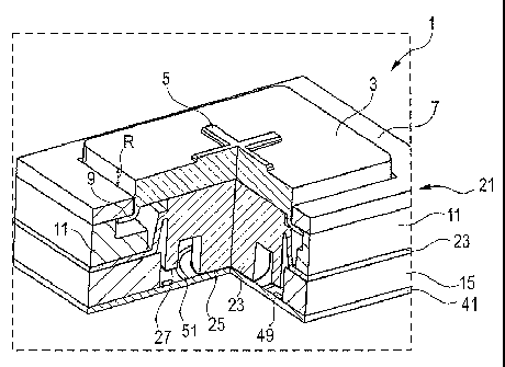
Fig. 5 represents a schematic overall view of the keyboard
1 according to the invention, with a key 21 that is
assembled and not actuated. The keyboard 1 can, for
example, be a security keyboard, or a so-called encrypted
PIN pad (EPP) for the secure input of PINs.
Here the key 21 has a keypad 3 of metal, which provides
additional protection and hinders attacks. The keypad 3 is
fitted with a flange 9 that engages under the edge of a
cover plate 7. By means of this configuration a removal of
the keypad 3 is inhibited. In addition too deep a
depression of the key 21 can be inhibited by means of a
stop frame 11 that together with the flange 9 prescribes a
maximum travel h. In this manner the structures in the
interior of the key are protected against an uncontrolled
application of force. On the surface of the keypad 3 is
located a tactile aid 5, here, for example, in the form of
a cross. The tactile aid 5 is three-dimensionally designed
in a tactile manner as a recess or an elevation so as to
ease the operation of the keyboard 1 for visually impaired
people.
The cover plate 7 is a metal overlay and serves to provide
stability and protection for the keyboard 1. Under the
cover plate 7 is located the stop frame 11. The switching
mat 23 follows as the next layer; this is integrated both
in the interior of the key 21 and also at the edge in the
supporting structure. Located at the edge of the key 21,
between switching mat 23 and contact plate 41, is a spacer
frame 15. This consists of metal and provides for the
necessary stability of the keyboard 1.
Under the key pad 3 is located the main component of the
switching mat 23. The switching mat 23 is in direct contact
with the key pad 3 and, via the security contact layer 25,
also with the contact plate 41; thus the security contact
elements 43, 45 are connected even when the key 21 is not
actuated, and thus the presence and integrity of the key 21
CA 02694921 2010-01-28
- 16 -
can be detected in the security circuit 37 (see Fig. 14)
under the contact plate 41.
As represented in Figs. 8 to 10, by an actuation of the key
21 a force is transferred from the keypad 3 onto the
switching mat 23, and the switching mat is compressed. As a
result the key contact layer 27 comes into contact with the
key contact elements 47, 49 on the contact plate 41 such
that a circuit is closed in an evaluation circuit 53 (see
Fig. 14) and the actuation of the key 21 can be registered.
As a result of the alternating arrangement of key contact
element inputs 45 and key contact element outputs 43 on the
contact plate 41, closure of the contacts can be ensured
even in the event of a non-uniform force distribution.
Since a key contact element input 45 is always adjacent to
a key contact element output 43, at least one input 45 is
connected with one output 43 by, for example, a one-sided
depression of the key 21.
Figs. 11 to 13 show a schematic view of a keyboard 1
according to the invention with a partially disassembled
key. Here the arrangements of the contact layers 25, 27 on
the switching mat 23 opposite to the contact elements 43,
45, 47, 49 are once more represented.
Fig. 14 shows a schematic overall view of a security
keyboard 101 according to the invention with a possible
security circuit 37 and a possible evaluation circuit 53.
The electrically conducting elements 43, 45, 47, 49 on the
contact plate 41 are connected with circuits 37, 53 in the
interior of a protected space. The protected space is
bounded underneath by a robust security cover 35 or a
similar covering providing protection from access. On the
side facing towards the keyboard the space can be protected
from attacks by a meandering layer 33.
If the security contact elements 43, 45 on the contact
plate 41 are closed by means of the security contact layer
25 of the switching mat 23, a voltage is detected across
CA 02694921 2010-01-28
- 17 -
the resistance 39 in the security circuit 37. Analogously,
if the key contact elements 47, 49 are closed a voltage is
detected across a resistance 55 in the evaluation circuit
53. Both the security circuit 37 and also the evaluation
circuit 53 are connected with an internal and/or external
data network 57. This enables a transfer of data, for
example, in the event of input of a PIN or a monetary
amount. In the event that any tampering with the keyboard
101 is detected, an alarm can be triggered via the
connection with the data network 57, or the deletion of
data can be initiated. Closure of the security contact
elements 43, 45 can be evaluated either with a static
signal or with dynamic signals.
The examples of embodiment represented in the figures
represent in an exemplary manner the mode of assembly and
the mode of operation of the keyboard 1 or the security
keyboard 101. In practice there are a plurality of options
for configuring the keyboard 1, 101 such that with the
actuation of the keyboard 1, 101 described a non-linear
force curve can be measured with, for example, at least one
distinctive pressure point. The shape of the force curve,
i. e. of the force-displacement diagram, alters according
to the configuration of the switching mat 23. For example,
the number and position of pressure points in the force-
displacement diagram can be varied by means of the geometry
of the switching mat 23. Non-linear force curves with
distinctive pressure points contribute to an improvement of
the tactile qualities/haptics of the key.
In conclusion it is observed that expressions such as
"having", or similar, are not designed to exclude the
possibility that further elements or steps can be provided.
Furthermore it should be noted that "a" or "an" does not
exclude a plurality of items. Moreover features described
in connection with the various forms of embodiment can be
combined with one another in any manner. It is further
observed that the reference symbols in the claims are not
to be construed as limiting the scope of the claims.
CA 02694921 2010-01-28
- 18 -
REFERENCE SYMBOL LIST
1 Keyboard
3 Keypad
Tactile aid
7 Cover plate
9 Flange
11 Stop frame
Spacer frame
21 Key
23 Switching mat
Electrically conducting layer
(security contact layer)
27 Electrically conducting layer
(key contact layer)
29 First level of the switching mat
31 Second level of the switching mat
33 Meandering layer
Security cover
37 Security circuit
39 Resistance
41 Contact plate
43 Electrically conducting element
(security contact element output)
Electrically conducting element
(security contact element input)
47 Electrically conducting element
(key contact element output)
49 Electrically conducting element
(key contact element input)
51 Guard ring
53 Evaluation circuit
Resistance
57 Data network
101 Security keyboard
a Radius of the security contact layer
b Radius of the inner ring of the security contact
element output
h Travel