Language selection

Search

Patent 2694991 Summary

Third-party information liability

Some of the information on this Web page has been provided by external sources. The Government of Canada is not responsible for the accuracy, reliability or currency of the information supplied by external sources. Users wishing to rely upon this information should consult directly with the source of the information. Content provided by external sources is not subject to official languages, privacy and accessibility requirements.

Claims and Abstract availability

Any discrepancies in the text and image of the Claims and Abstract are due to differing posting times. Text of the Claims and Abstract are posted:

  • At the time the application is open to public inspection;
  • At the time of issue of the patent (grant).
(12) Patent: (11) CA 2694991
(54) English Title: IMPROVED ORIFICE HOLDER CONSTRUCTION
(54) French Title: CONSTRUCTION AMELIOREE D'UN SUPPORT D'ORIFICE
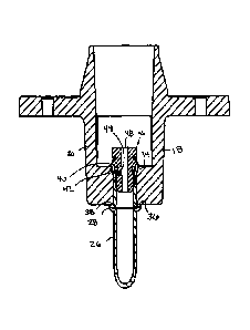
Status: Granted and Issued
Bibliographic Data
(51) International Patent Classification (IPC):
  • F24C 03/08 (2006.01)
  • F16L 05/00 (2006.01)
  • F23D 14/62 (2006.01)
(72) Inventors :
  • FROST, TIMOTHY (United States of America)
  • LEESEBERG, TONY BYRON (United States of America)
(73) Owners :
  • BURNER SYSTEMS INTERNATIONAL, INC.
(71) Applicants :
  • BURNER SYSTEMS INTERNATIONAL, INC. (United States of America)
(74) Agent: NEXUS LAW GROUP LLP
(74) Associate agent:
(45) Issued: 2015-10-13
(86) PCT Filing Date: 2008-08-13
(87) Open to Public Inspection: 2009-03-05
Examination requested: 2013-02-20
Availability of licence: N/A
Dedicated to the Public: N/A
(25) Language of filing: English

Patent Cooperation Treaty (PCT): Yes
(86) PCT Filing Number: PCT/US2008/009712
(87) International Publication Number: US2008009712
(85) National Entry: 2010-01-13

(30) Application Priority Data:
Application No. Country/Territory Date
11/848,736 (United States of America) 2007-08-31

Abstracts

English Abstract


An orifice holder
assembly provides a boss connected
by at least one arm to a base having
an outlet therethrough. The boss is
provided below the outlet. A tube is
inserted through the boss until a bead
contacts a first boss surface and the
tube end is then deflected to form a lip
where the lip and the bead connects
the tube to the boss. An orifice body
is then inserted in the tube end.


French Abstract

L'invention porte sur un support d'orifice présentant un bossage relié par au moins un bras à une base munie d'un orifice de sortie. On insère un tube à travers le bossage jusqu'à ce qu'un bourrelet touche une première surface du bossage, puis on défléchit l'extrémité du tube pour former une lèvre, ladite lèvre et le bourrelet assurant la fixation du tube au bossage. Un corps d'orifice est alors inséré dans l'extrémité du tube.

Claims

Note: Claims are shown in the official language in which they were submitted.

1. An orifice holder assembly comprising:
an orifice holder having a base connected by at least one arm to a boss, said
boss located
below the base and having a bore therethrough extending from a first boss
surface to a second
boss surface with said second boss surface located above the first boss
surface;
a tube received by the boss, said tube having a preformed bead disposed about
the tube
spaced from a tube end, said bead contacting the first boss surface with a
portion of the tube
extending through the bore of the boss, said tube then deformed at the tube
end to provide a lip
with a lip engagement surface in contact with the second boss surface external
to the bore with
the lip and the bead forming a mechanical connection of the tube to the boss
by entrapping a
portion of the boss between the lip and the bead; and
an orifice body connected to the tube end and having a bore therethrough, said
orifice
body located below the base with a space above the orifice body and below the
base and said
orifice body terminating internal to the boss above the first boss surface.
2. The orifice holder assembly of claim 1 wherein the orifice body has
external threads
which are in contact with an internal portion of the tube toward the tube end.
3. The orifice holder assembly of claim 1 wherein at least one arm is
integrally connected to
and extends from the boss.

4. The orifice holder assembly of claim 3 wherein the at least one arm is
integrally
connected to the base and the first boss surface against the bead is the
lowest portion of the boss.
5. The orifice holder assembly of claim 1 wherein the orifice holder
further comprises an
outlet which extends through the base above the orifice body.
6. The orifice holder assembly of claim 1 wherein the at least one arm
further consists of two
arms extending from the base to the boss.
7. The orifice holder assembly of claim 6 wherein the two arms are
oppositely and
symmetrically disposed relative to the orifice body.
8. The orifice holder assembly of claim 1 manufactured by the process of
providing a tube
end having a smaller cross section than the bore of the boss until physically
deflected to provide
the lip, inserting the tube end through the bore of the boss until the bead
contacts the first boss
surface, and then deflecting the tube end to provide the lip external to the
bore of the boss.
9. The orifice holder assembly of claim 8 wherein the process of
manufacturing the orifice
holder assembly further comprises after deflecting the tube end to provide the
lip, then inserting
the orifice body at the tube end.
7

10. The orifice holder assembly of claim 9 wherein the orifice body has
self-tapping external
threads which connect the orifice body to the tube end.
11. An orifice holder assembly comprising:
an orifice holder having an outlet, and the orifice holder further having a
base connected
by at least one arm to a boss, said boss located under the outlet and having a
bore therethrough
extending from a first boss surface to a second boss surface with said second
boss surface located
above the first boss surface;
a tube received by the boss, said tube having a preformed bead disposed about
the tube
spaced from a tube end, said bead contacting the first boss surface with a
portion of the tube
extending through the bore of the boss, said tube deformed after insertion to
provide a lip at the
tube end with a lip engagement surface in contact with the second boss surface
external to the
bore with the lip and the bead forming a mechanical connection of the tube to
the boss by
entrapping portion of the boss between the lip and the bead; and
an orifice body connected to the tube end and having a bore therethrough, said
orifice
body located below the outlet with a space above the orifice body and below
the outlet, and said
orifice body terminating internal to the boss above the first boss surface.
12. The orifice holder assembly of claim 11 manufactured by the process of
providing a tube
end having a smaller cross section than the bore of the boss until physically
deflected to provide
the lip, inserting the tube end through the bore of the boss until the bead
contacts the first boss
surface, and then deflecting the tube end to provide the lip external to the
bore of the boss.
8

13. The orifice holder assembly of claim 11 wherein the tube end is
physically deflected with
a device extending through the outlet of the orifice holder which is removed
after forming the
lip.
14. The orifice holder assembly of claim 13 wherein the process of
manufacturing the orifice
holder assembly further comprises after deflecting the tube end to provide the
lip, then inserting
the orifice body at the tube end.
15. The orifice holder assembly of claim 14 wherein the orifice body has
self-tapping
external threads which connect the orifice body to the tube end.
16. The orifice holder assembly of claim 11 wherein the orifice body has
external threads
which are in contact with an internal portion of the tube toward the tube end
and the bead is
located external to the bore.
17. The orifice holder assembly of claim 11 wherein the at least one arm is
integrally
connected to the base and the boss and the bead is located below the first
boss surface.
18. The orifice holder assembly of claim 11 wherein the at least one arm
further comprises
two arms extending from the base to the boss and at least a portion of the lip
is located above the
second boss surface.
9

19. The
orifice holder assembly of claim 18 wherein the two arms are oppositely
disposed
relative to the orifice body.

Description

Note: Descriptions are shown in the official language in which they were submitted.


CA 02694991 2014-11-12
IMPROVED ORIFICE HOLDER CONSTRUCTION
Field of the Invention
[0001] The present invention relates to a tubing assembly and more
particularly, to tube orifice
and orifice holding assembly improvements.
Background of the Invention
[0002] Member and tube assemblies such as the improvements shown in U.S.
Patents 5,607,194
and 5,727,303 have been performed by the applicant. While these improvements
are useful, in
order to connect the tube and orifice to an orifice holder, a separate
connection system has been
utilized to perform that connection. In the prior art, this connection was
been done typically by
screwing the threads such as the threads 41 of Figure 4 of U.S. Patent No.
5,607,194 into
cooperating threads of an orifice holder. While this would provide easy
installation replacement,
it also could allow for such conditions to exist as imprecise placement of a
tube relative to the
orifice holders, (i.e., such as if the fitting was not inserted the proper
amount). Furthermore,
since the tubes which are connected to the fittings are not usually straight
when they are installed
in an oven, it may be extremely difficult to rotate a tube relative to an
installed orifice holder.
Furthermore, since there are not normally any moving parts at this location
once installed, the
opportunity for failure of these component parts is particularly small so
replacement of one part
relative to the other is not believed to be commonly performed.
[0003] While the prior art technology is certainly useful and continues to be
widely practiced by
the applicant, an improved manufacturing method and completed apparatus is
believed to be
desirable at least for some applications.
1
(Replacement Sheet)

CA 02694991 2014-11-12
Summary of the Invention
[0004] It is an object of the present invention to provide a tube securely
connected to an orifice
holder independent of cooperating threads.
[0005] It is another object of the present invention to provide a tube
connected to an orifice
holder in an improved manner.
[0006] It is another object of the present invention to provide a tube secured
to an orifice holder
such that the tube is connected to the orifice holder by the use of at least
one tool applied through
an air/fuel outlet of the orifice holder during the manufacturing process.
[0007] Accordingly, an orifice holder, tube and orifice assembly of the
presently preferred
embodiment preferably includes a tube which includes a bead or other stop on
an exterior surface
of the tube which contacts a first position of an orifice holder. A portion of
the tube passes
through a bore extending from the first position to a second position in the
orifice holder. A tool
such an a mandrel is preferably inserted through an outlet of the orifice
holder and is used to
flare out the tube at a second position of the orifice holder so that the tube
is then secured to the
orifice holder so that the orifice holder outlet as well as the tube outlet
are disposed beyond the
second position of the orifice holder. The tube is then provided with an
orifice such as by
screwing the orifice into the tube. The preferred method is believed to
provide a cost savings to
the manufacturer through construction while providing a high quality product
for the completed
product.
2
(Replacement Sheet)

CA 02694991 2014-11-12
Brief Description of the Drawings
[0008] The particular features and advantages of the invention as well as
other objects will
become apparent from the following description taken in connection with the
accompanying
drawings in which:
Figure 1 shows a side view of an assembled orifice holder connected to a tube
and an
orifice of the presently preferred embodiment of the present invention from a
side view;
Figure 2 shows a top view of the orifice holder assembly shown in Figure 1;
Figure 3 shows a process of manufacturing the orifice holder assembly as shown
in
Figures 1 and 2; and
Figure 4 shows a detailed cross sectional view of a detail marked as A in
Figure 3 after
the manufacturing step has been completed and the orifice installed as would
be in Figures 1-2.
Detailed Description of the Preferred Embodiment
[0009] Figure 1 shows an orifice holder assembly 10 having an orifice holder
12 which is
typically a cast part, and in the preferred embodiment, has been cast out of
aluminum. Of
course, other manufacturing techniques could be utilized to make other orifice
holders. Casting
has been found to be economical while providing a quality product.
[00010] The orifice holder 12 has an outlet 14, shown in Figure 2, at a top
end 16. The outlet 14
of this embodiment is illustrated as being at least substantially round and
directs a fuel gas
mixture from below through the outlet 14 past the top end 16 for use by a
burner which is not
shown. Many burner designs have been constructed. Other orifice holders have
been utilized in
the past for such uses.
[00011] This orifice holder has two arms 18,20 which are shown in Figure 3,
extending from a
base 22. These arms connect at a boss 24 which is configured to have a bore
therethrough which
3
(Replacement Sheet)

CA 02694991 2014-11-12
receives a portion of tube 26 therethrough. A bead 28 is preferably utilized
to stop the tube 26 a
desired position relative to the boss 24 as shown in Figures 3 and 4 during
the assembly process.
Other mechanisms known in the art can also be utilized which provide a stop so
that no further
travel of the tube 26 through the bore can occur due to the presence of the
bead 28.
[00012] Once the tube 26 is installed as shown in Figure 3, an anvil 30 or
other device is
inserted through the outlet 14 of the orifice holder 12 and causes the end 32
of the tube 26 to be
deflected such as shown in Figure 4 so that the boss 24 of the orifice holder
is secured relative to
the lip 34 created by the bent tube 26 and the bead 28. This method of
construction is believed
to be a large improvement over the prior art in that in the prior art such as
shown in U.S. Patent
Nos. 5,607,194 and 5,727,303.
[00013] In the prior art, a separate nut and thread arrangement was utilized
to secure those
fittings to orifice holders. By manufacturing an orifice holder as shown and
described in the
figures herein, at least several manufacturing steps and parts can be omitted
which is believed to
result in a cost savings to at least the manufacturer, if not the end user.
[00014] As shown in Figure 4, the bead 28 has a boss engagement flange 36
which is shown
adjacent to boss surface 38 and lip 34 as a lip engagement surface 40 which
engages boss surface
42. Additionally, arms 18,20 are illustrated extending above the lip 34 as
well as above orifice
body 46.
[00015] After connecting the tube 26 to the orifice holder 12, if the tube end
32 is not already
provided with threads is may be tapped so that it has threads 44 as shown in
Figure 4 by
directing the tap (not shown) through the outlet 14 and providing the threads
44 as shown in
Figure 4 in a similar manner as anvil 30 is shown applied in Figure 3.
Alternatively, and more
preferably, the orifice body 46 may make its own threaded connection (i.e.,
somewhat self
4
(Replacement Sheet)

CA 02694991 2014-11-12
tapping). The orifice body 46 with its cooperating threads is then inserted
preferably through the
outlet 14 so that its cooperating threads engage threads 44 so it can be
provided in the position
shown in Figure 4. The orifice body 46 then has bore 48 which allows for the
gas from the tube
26 to then mix with air in the space 49 prior to being directed through the
outlet 14 where mixing
can further continue to occur within a burner (not shown) before being lit and
providing heat in a
stove type configuration.
[000161 While it is alternatively possible to provide an anvil 30, tap or
orifice at the space 48
below to the base 22 to flare the lip 34 and/or install the orifice body 46 in
a similar manner, the
presently preferred embodiment as described herein provides the connection of
the tube 26 to the
boss 24 through application through the outlet 14 as well as the machining of
the tube 26 to
provide threads 44 if not done prior to the installation of the tube 26 to the
boss 24. Finally it is
also presently preferred to install the orifice body 46 through the outlet 14.
[00017] It is important to remember that in the prior art the machining of the
tube 26 to a fitting
has been performed before installing the fitting to an orifice holder 12.
(Repldcement Sheet)

Representative Drawing
A single figure which represents the drawing illustrating the invention.
Administrative Status

2024-08-01:As part of the Next Generation Patents (NGP) transition, the Canadian Patents Database (CPD) now contains a more detailed Event History, which replicates the Event Log of our new back-office solution.

Please note that "Inactive:" events refers to events no longer in use in our new back-office solution.

For a clearer understanding of the status of the application/patent presented on this page, the site Disclaimer , as well as the definitions for Patent , Event History , Maintenance Fee  and Payment History  should be consulted.

Event History

Description Date
Maintenance Request Received 2024-08-23
Maintenance Fee Payment Determined Compliant 2024-08-23
Common Representative Appointed 2019-10-30
Grant by Issuance 2015-10-13
Inactive: Cover page published 2015-10-12
Pre-grant 2015-06-18
Inactive: Final fee received 2015-06-18
Letter Sent 2015-05-28
Notice of Allowance is Issued 2015-05-28
Inactive: QS failed 2015-03-25
Inactive: Approved for allowance (AFA) 2015-03-25
Amendment Received - Voluntary Amendment 2014-11-12
Inactive: S.30(2) Rules - Examiner requisition 2014-05-14
Inactive: Report - No QC 2014-04-29
Letter Sent 2013-03-04
Request for Examination Received 2013-02-20
Request for Examination Requirements Determined Compliant 2013-02-20
All Requirements for Examination Determined Compliant 2013-02-20
Inactive: Agents merged 2011-07-07
Inactive: IPC assigned 2010-04-21
Inactive: First IPC assigned 2010-04-21
Inactive: IPC removed 2010-04-21
Inactive: Cover page published 2010-04-07
Inactive: Notice - National entry - No RFE 2010-04-06
Inactive: Office letter 2010-04-06
Letter Sent 2010-04-06
Inactive: IPC assigned 2010-04-01
Application Received - PCT 2010-03-30
Inactive: IPC assigned 2010-03-30
Inactive: IPRP received 2010-03-30
Inactive: First IPC assigned 2010-03-30
Inactive: IPRP received 2010-01-14
National Entry Requirements Determined Compliant 2010-01-13
Application Published (Open to Public Inspection) 2009-03-05

Abandonment History

There is no abandonment history.

Maintenance Fee

The last payment was received on 2015-05-20

Note : If the full payment has not been received on or before the date indicated, a further fee may be required which may be one of the following

  • the reinstatement fee;
  • the late payment fee; or
  • additional fee to reverse deemed expiry.

Patent fees are adjusted on the 1st of January every year. The amounts above are the current amounts if received by December 31 of the current year.
Please refer to the CIPO Patent Fees web page to see all current fee amounts.

Owners on Record

Note: Records showing the ownership history in alphabetical order.

Current Owners on Record
BURNER SYSTEMS INTERNATIONAL, INC.
Past Owners on Record
TIMOTHY FROST
TONY BYRON LEESEBERG
Past Owners that do not appear in the "Owners on Record" listing will appear in other documentation within the application.
Documents

To view selected files, please enter reCAPTCHA code :


To view images, click a link in the Document Description column. To download the documents, select one or more checkboxes in the first column and then click the "Download Selected in PDF format (Zip Archive)" or the "Download Selected as Single PDF" button.

List of published and non-published patent-specific documents on the CPD .

If you have any difficulty accessing content, you can call the Client Service Centre at 1-866-997-1936 or send them an e-mail at CIPO Client Service Centre.


Document
Description 
Date
(yyyy-mm-dd) 
Number of pages   Size of Image (KB) 
Abstract 2010-01-12 2 61
Description 2010-01-12 5 199
Drawings 2010-01-12 2 28
Claims 2010-01-12 4 107
Representative drawing 2010-04-06 1 8
Description 2014-11-11 5 171
Claims 2014-11-11 5 117
Representative drawing 2015-09-20 1 6
Confirmation of electronic submission 2024-08-22 3 79
Reminder of maintenance fee due 2010-04-14 1 115
Notice of National Entry 2010-04-05 1 197
Courtesy - Certificate of registration (related document(s)) 2010-04-05 1 102
Acknowledgement of Request for Examination 2013-03-03 1 177
Commissioner's Notice - Application Found Allowable 2015-05-27 1 162
Fees 2012-06-14 1 156
Fees 2013-05-15 1 156
PCT 2010-01-13 6 299
PCT 2010-01-12 2 74
PCT 2010-01-13 6 298
Correspondence 2010-04-05 1 15
Fees 2010-05-03 1 34
PCT 2010-07-28 1 46
Fees 2011-05-15 1 202
Fees 2014-05-14 1 25
Fees 2015-05-19 1 26
Final fee 2015-06-17 1 35
Fees 2016-08-03 1 26
Maintenance fee payment 2017-07-25 1 26