Note: Descriptions are shown in the official language in which they were submitted.
CA 02695284 2010-02-01
WO 2009/017927 PCT/US2008/068902
SYS'i'EMS AND METHODS OF BREWING LOW-CHOLESTEROL ESPRESSO
TECHNICAI, FIELD
[0001] The present application generally relates to systems and methods of
brewing
espresso, and more particularly relates to systems and methods of brewing
relatively low-
cholesterol espresso.
BACKGROUND
10002] Espresso is a type of beverage made by forcing water through ground
coffee
beans at high pressure to extract solids and oils from the coffee beans. The
solids and oils
become dispers.-d throughout and emulsified with the water. Thc result is a
thick and
flavorful beverage that is normally consumed short[y after extraction or is
mixed with
other liquids to form an espresso-based beverage. For example, an "Americano"
is an
espresso-based beverage made by mixing espresso with water while cappuccino is
an
espresso-based beverage made by mixing espresso, milk, and milk foam.
10003] Espresso and espresso-based beverages tend to be high in cholesterol.
Coffee
beans may inchjde high-cholesterol oils that are extracted along with the
other solids and
oils during the brewing process and become incorporated into the espresso.
Teipenes, for
example, are oils found in coffee beans that tend to contain LDL cholesterol.
The
presence of high-cholesterol oils such as terpenes in espresso may be
undesirable to
individuals who want to limit the intake of cholesterol for health reasons.
For example,
LDL cholesterol in particular has been shown to increase the risk of diseases
such as heart
disease, among; others.
SIJM?vIARY
100041 "I'he present application describes a low-cholesterol brewed beverage
disperrser.
The low-cholesterol brewed beverage dispenser includes a high-pressure brewing
area, a
low-pressure area, and a filter. The high-pressure brewing area is confiryured
for brewing
water and a brevvable material at a relatively high pressure. "E'he low-
pressure area is
positioned to receive the brewed beverage from the high-pressure brewing area.
The
CA 02695284 2010-02-01
WO 2009/017927 PCT/US2008/068902
2
pressure in the low-pressure area is relatively lower than the pressure in the
high-pressure
brewing area. The filter is positioned in the low-pressure area. The filter is
configured to
remove at least some high-cholesterol oils from the beverage.
[0005] The present application further describes a method of making relatively
low-
cholesterol espresso. The method includes brewing espresso at a relatively
high pressure,
reducing the pressui-e of the espresso, and filtering the espresso to remove
at least some of
the high-cholesterol oils from the espresso,
[0006] The preser.it application also describes a pod cartridge. The pod
cartridge
includes a sidewall, a base, and a filter. The sidewall defines an interior
space. The base
separates the interior space into a brewing area and an accumulation area. The
brewing
area is configured for brewing espresso at a relatively high pressure and the
accumulation
area is configured tiir allowing the espresso to return to a lower pressure.
The filter is
positioned in the accumulation area. The filter is configured to remove at
least some high-
cholesterol oils froni the espresso after the pressure of the espresso has
been lowered.
BRIEF DESCRIPTION OF THE DRAWINGS
[0007] The preserit disclosure may be better understood with reference to the
following
drawings. Matching reference numerals designate corresponding parts throughout
the
drawings, and components in the drawings are not necessarily to scale.
100081 Fig. I is a perspective view of one embodiment of a beverage dispenser
system
for use with the present invention.
[0009] Fig. 2 is a top plan view of the beverage dispenser system of Fig. 1.
[0010] Fig. 3 is a perspective view of a turret system of the beverage
dispenser system of
Fig. 1.
[0011] Fig. 4 is a perspective view of an injector assembly of the beverage
dispenser
system of Fig. 1, with the guide wheels and the return spring of the support
plate shown in
phantom lines.
[0012] Fig. 5 is a rear perspective view of the injector assembly of the
beverage
dispenser system of'Fig. 1, with the idler wheel and the limit switch shown in
a cut away
view.
[0013] Fig. 6 is perspective view of a pod as described herein.
[0014] Fig. 7 is perspective view of a pod as described herein.
CA 02695284 2010-02-01
WO 2009/017927 PCT/US2008/068902
3
[0015] Fig. 8 is a side cross-sectional view of the pod of Fig. 6.
[0016] Fig. 9 is a top perspective view of the pod o1'Fig. 6.
100171 Fig. 10 is a bottom perspective view of the pod of Fig. 6.
10018) Fig. I 1 is a side cross-sectional view of a pod showing the lid.
100191 Fig. 12 is a side cross-sectional view of'a pod cartridge with an
amount of
brew ing material positioned therein.
100201 Fig. 13 is a side plan view of an alternative embodiment of the lip of
the pod of
Fig. 6.
[0021] Fig. 14 is a side cross-sectional view of the pod of Fig. 13.
I 0 100221 Fig. 15 is a side plan view of a grinder for use with the invention
as described
herein.
[0023] Fig. 16 is a side plan view of an embodiment of a!ow-cholesterol
espresso
dispenser.
[0024] Fig. 17 is a perspective view of an embodiment of a pod cartridge that
can be
used with the beverage dispenser system of Figs. 1-5.
100251 Fig. 18 is a perspective view of the pod cartridge shown in Fig. 17.
100261 Fig. 19 is a cross-sectional view of the pod cartridge shown in Fig.
17, taken
along line 19-19.
100271 Fig. 20 is a block diagram illustrating an embodiment of a inethod of
rnaking
relatively low-cholesterol espresso and espresso-based beverages.
DETAILED DESCRIPTION
[0028] Referring now to the drawings, in which like numerals refer to like
elements
throughout the several views, Figs. I and 2 show one application of a beverage
dispenser
system 100. In these figures, a pod brewing apparatus 300 is shown. Ttte pod
brewing
apparatus 300 may include a heat exchanger 150 positioned within a hot water
reservoir
160 and in commLuiication with an injection nozzle 200 as is shown. In this
embodiment,
the eleinents of the beverage dispenser system 100 as a whole are mounted onto
a
dispenser frame 305. The dispenser frame 305 rnay be made out of'sta'snless
steel,
aluminum, other types of inetals, or other types of substantially noncorrosive
materials.
[0029] The injection nozzle 200 may interact with one or tnore pod cartridges
210 so as
to produce the desired beverage in a cup 230 or any other type of receptacle.
'I'he poci
CA 02695284 2010-02-01
WO 2009/017927 PCT/US2008/068902
4
cartridges 210 may be positioned in the beverage dispenser system 100 within a
turret
assembly 310. The turret assembly 310 may be fixedly attached to the dispenser
frame
305. As is shorvn ir- Fig. 3. the turret assembly 310 may include a turret
plate 320
positioned within a turret frame 325. The turret frame 325 may be made out of
stainless
steel, aluminum, other types of conventional metals, or sitnilar types of
substantially
noncorrosive materiials. The turret plate 320 may be substantially circular or
have any
convenient shape. The turret plate 320 may include a number of pod apertures
330. The
pod apertures 330 may be sized to accommodate the pod cartridges 210. The
turret plate
320 may spin about a turret pin 340. A turret motor 350 may drive the turret
assembly
310. The turret moitor 350 may be a conventional AC motor or a similar type of
device.
'l'he turret motor 350 may drive the turret assembly 310 at about six (6) to
about thirty (30)
rpm, with about twenty-five (25) rpm preferred.
10030] The turret plate 320 also may have a number of detents 360 positioned
about its
periphery. The detents 360 niay be positioned about each of the turret
apertures 330, The
detents 360 may cooperate with one or more limit switches 365 so as to control
the
rotation of the turret plate 320. The rotation of the plate 320 may be stopped
when the
limit switch 360 encounters one of the detents 360. Rotation of the plate 320
may be
controlled by similar types of devices.
100311 Positioned. adjacent to the turret assembly 310 may be an injector
assembly 400.
'1'he irijector assembly 310 may be fixedly attached to the dispenser frame
305. The
injector assembly 400 also may include an injector frame 410 extending above
the turret
assembly 310. The injector frame 410 may be made out of stainless steel, other
types of
metals, or similar types of substantially noncorrosive materials,
[0032] Referring now to Figs. 4 and 5, the injector assembly 400 may include
the
injection nozzle 201) as described above with respect to Fig. 2. The injection
nozzle 200
may have a narrow tip so as to penetrate the pod cartridge 210 if needed or a
wide mouth
to accommodate the entire pod cartridge 210. The injector assembly 400 may
include an
injector head 420 that cooperates with the injection nozzle 200. I'he injector
head 420
may be slightly larger in diameter than the pod cartridges 210. The injector
head 420 also
may be made out oif stainless steel, plastics, or similar types of
substantially noncorrosive
materials. The injector head 420 may include a sealing ring positioned about
its lower
periphery. The sealing ring may be made otit of rubber, silicone, or other
types of elastic
CA 02695284 2010-02-01
WO 2009/017927 PCT/1JS2008/068902
materials such that a substantially water tight seal mav be tormed between the
injector
head 420 and the pod cartridge 210. The heat exchanger 150 inay be in
communication
with the injector head 420 so as to provide hot, pressurized water to the pod
cartridges
210.
5 (0033] The injector head 420 rnay be moveable in a substantially vertical
plane via a
cam system 440. (The terms "vertical" and "horizontal" are used as a frame of
reference
as opposed to absolute positions. 't'he injector head 420 and the other
elenlents described
herein may operate in any orientation.) A catn systern drive motor 450 may
drive the cam
svstem 440. The drive motor 450 may be a conventional AC motor similar to the
turret
motor 350 described above. The drive motor 450 also may be a shaded pole or a
DC type
motor. The drive motor 450 may rotate an eccentric cam 460 via a drive belt
system 470.
The drive motor 450 and the gear system 470 may rotate the eccentric cain 460
at about
six (6) to about thirty (30) rpm, with about twenty-f3ve (25) rpm preferred.
The eccentric
cam 460 tnay be shaped such that its lower position may have a radius of'about
4.1 to
about 4.8 centimeters (about 1.6 to 1.9 inches) while its upper position may
have a radius
ofabout 3.5 to 4.1 centimeters (about 1.3 to about 1.7 inches).
[00341 The eccentric cam 460 may cooperate with an idler wheel 480. The idler
wheel
480 may be in communication with and mounted within a support plate 490. "I'he
support
plate 490 may maneuver about the injector frame 410. "1'he support plate 490
trtay be
made out of staitiless steel, other types of steei, plastics, or other
materiais. The support
plate 490 may be fixedly attached to the injector head 420. The support plate
490 nlay
have a number ofguide wheels 500 positioned thereon such that the support
plate 490 can
move in the vertical direction within the injector !'rame 410. A return spring
520 also may
be attached to the support plate and the injector frame 410. A limit switch
530 rnay be
positioned about the cam 460 such that its rotation may not exceed a certain
atnount.
[0035] "I he injector head 420 thus may nianeuver up and down in the vertical
direction
via the cam systeni 440. Specifically, the drive motor 450 may rotate the
eccentric cam
460 via the gear system 470. As the eccentric cam 460 rotates with an ever-
increasing
radius, the idler wheel 480 pushes the support plate 490 downward such that
the injector
head 420 comes in contact with a pod cartridge 210. The eccentric cam 460 may
lower
the injector head 420 by about 6_4 to about 12.7 millimeters (about one-
duarter to about
one-half inch). Once the injector head 420 comes into contact with the pod
cartridgc 210.
CA 02695284 2010-02-01
WO 2009/017927 PCT/US2008/068902
6
the eccentric cam 460 may continue to rotate and increases the pressure on the
pod
cartridge 210 until the cam 460 reaches the limit switch 530. The injector
head 420 may
engage the pod cartridge 210 with a downward force of about 136 to 160
kilograms (about
300 to 350 pounds). The sealing ring thus may form a substantially airtight
and water
tight seal about the pod cartridge 210. The drive motor 450 may hold the cam
460 in place
for a predetermined amount of time. The cam system 440 then may be reversed
such that
the injector head 420 returns to its original position.
[00361 Once the i:njection nozzle 200 of the injector head 420 is in contact
with the pod
cartridge 210, the hot, high pressure water may flow from the heat exchanger
150 into the
injector head 420. The pressure of the water flowing through the pod cartridge
210 may
vary with the nature of the brewing material 550 therein.
100371 Figs. 6- 12 show an embodiment of the pod cartridge 210 that may be
used with
the beverage dispenser system 100 or other types of beverage systems. In fact,
the pod
cartridge 210 may be used with any type of mixable material, flavoring,
additives, and
other substances. The pod cartridge 210 may be substantially in the shape of a
cup 600.
The cup 600 may be made out of a conventional thermoplastic such as
polystyrene,
polyethylene, polypropylene and similar types of materials. Alternatively,
stainless steel
or other types of substantially non-corrosive materiats also may be used. The
cup 600
may be substantially rigid so as to withstand the heat and pressure of the
brew cycle
without imparting any off-tastes. As described below, however, by the term
"rigid" we
mean that the cup 600 may flex or deform slightly while under pressure.
[0038] The cup 600 inay include a substantially circular sidewall 610 and a
substantially
flat base 620. Other shapes also may be used. The sidewal1610 and the base 620
of the
cup 600 may be molded and form a unitary element or a separate sidewal1610 and
a
separate base 620 rnay be fixably attached to each other. The side-svall 610
and the base
620, as well as the cup 600 as a whole, may have any convenient diameter so as
to
accommodate the pod apertures 330 of the turret plate 320 of the turret
assembly 310 and
the injector head 420 of the injector 400. Alternatively, the sidewall 610 and
the base 620
of the cup 600 may have any convenient diameter so as to accommodate other
types of
beverage dispenser systems 100 or similar types of devices.
100391 By way of example, the sidewall 610 may have an inside diameter of
about 39.3
millimeters (about 1.549 inches) with a wall thickness of about 1.1
millimeters (about
CA 02695284 2010-02-01
WO 2009/017927 PCT/US2008/068902
7
0.043 inches), The sidewall 610 may have a slight taper from the top to the
bottont. Other
sizes or dimensions may be used as desired.
[00401 "1'he cup 600 as a whole may have a variable depth depending upon the
amount of
brewing material intended to be used therein. In the case of the cup 600
intended to be
used for about a 355 milliliter (about twelve (12) ounce) beverage, the cup
600 may have a
total height of about 28.7 millirneter (about 1. 13 iriches) and a useable
inside height of
about 17.1 millimeters (about 0.674 inches). The height to diameter ratio for
the 355
milliliter cup 600 therefore may be about 0.73 for the total height and about
0.435 for the
usable inside lieight_ '1'he cup 600 rnay have about 6.4 grams of a
polypropylene material.
[00411 A cup 600 to be used with, for example, about a 237 milliliter (about
an eight (8)
ounce) beverage may have a height of about 22.5 millimeters (about 0,887
inches) and a
usable inside height of about 11.8 millimeter (about 0.463 inches). The ratio
thus may be
about 0.57 for the total height and about 0.3 for the usable inside height.
Thc cup 600 may
have about 5.8 grams of a polypropylene material.
100421 These ratios between dianieter and depth provide the cup 600 and the
cartridge
210 as a whole with sufficient strength and rigidity while using a minimal
amount of
material. The cartridge 210 as a whole may have about five (5) to about eight
(8) grams of
plastic material therein when using, for example, a polypropylene
homopolynter. As a
result, the cup 600 and the cartridge 210 as a whole may withstand
temperatures of'over
about 93 degrees Celsius (about 200 degrees Fahrenheit) for up to sixty (60)
seconds or
more at a hydraulic pressure of over about ten (10) bar (about 1 50 pounds per
square
inch). Although the cup 600 having these ratios may flex or deform somewhat,
the cup
600 and the cartridge 210 as a whole should withstand the expected water
pressure passing
therethough. These dimensioris and characteristics are for the purpose of
example only.
The sidewall 610 and the base 620 of the cup 600 may take any desired or
convenient size
or shape_ For example, the sidewall 610 may be straight. tapered, stepped. or
curved if
desired.
[0043] '1'he base 620 may include a number of apertures 640 formed therein. "I
he
apertures 640 may extend through the width of the base 620. I'he apertures 640
may be
largely circular in shape with a diameter each of about 1.6 rnillimeters
(about 0.063
inches). Any desired shape or size, however, may be used, In this embodiment,
about 54
apertures 640 are used herein, although any number may be used. Thc selected
number
CA 02695284 2010-02-01
WO 2009/017927 PCT/US2008/068902
8
and size of apertures 640 provide the appropriate pressure drop when a cup 600
of a given
dimension is used.
[0044] The base 620 also may have a number of support ribs 650 positioned
thereon.
An inner circular rib 660, an outer circular rib 670, and a number of radial
ribs 680 may be
used. In this embodiment, the ribs 650 may have a depth of about one (1)
millimeter
(about 0.04 inches), although any desired thickness may be used. Likewise, any
desired
number and/or shape of the ribs 650 may be used. The design of the ribs 650
also
provides increased support and stability to the cartridge 210 as a whole with
a minimum
amount of material.
[0045] The sidewal1610 of the cup 600 also may include an upper lip 700. The
upper
lip may include a substantially flat top portion 710. The flat top portion 710
may have a
width of about 3.45 millimeters (about 0.136 inches) and a height in the
vertical direction
of about 3.4 millirneters (about 0.135 inches). The lip 700 may be configured
to
accommodate the size of the pod apertures 330 and the injector head 420 as
well as the
expected force of the hot water provided by the injector head 420 while using
as little
material as possible. This is particularly true given that the cartridge 210
as a whole
generally is supported only about its lip 700 during the injection process.
[0046] Figs. 13 and 14 show an alternative embodiment of the lip 700. In this
embodiment, a lip 720 may include the substantially flat top portion 710 and a
downwardly angled flanged 730 that extends from the top portion 730. The
flange 730
may extend downvvard so as to form a pocket 740 with the sidewall 610. The top
of the
pocket 740 may have a curved inner radius. The flange 730 and the pocket 740
of the lip
720 are sized to accommodate the size of the pod apertures 330.
(0047] Referring again to Figs. 6-- 12, the sidewal1610 of the cup 600 also
may include
a number of cutouts 760 formed therein. In this embodiment, a first cutout
770, a second
cutout 780, and a third cutout 785 may be used. Any number of cutouts 760,
however,
may be used. For example, only two (2) eutouts 760 may be used with a 237
milliliter
(about an eight (8) ounce) cup 600. The cutouts 760 may be continuous around
the inner
circumference of the sidewalls 610 or the cutouts 760 may be intermittent.
100481 'I'he cutotrts 760 may cooperate with a lid 790. The lid 790 may have
an edge
800 that is substantially wedge-shaped about its perimeter for insertion
within a cutout
760. The use of the cutouts 760 ensures that the lid 790 remains in place. The
edge 800
CA 02695284 2010-02-01
WO 2009/017927 PCT/US2008/068902
9
may be continuous or intermittent so as to mate with the cutouts 760. The lid
790
preferably is bowed inwardly or may be largely concave in shape. The lid 790
may have
about 0.8 gratns of a polypropylene material.
[00491 The lid 790 may be placed in one of the cutouts 760 depending upon the
amount
of brewing material that is to be placed in the cup. "fhe lid 790 may be bowed
downward
in a concave shape so as to tap the brewing material 550 down under pressure
and to keep
the brewing material therein from shifting. "l'he lid 790 may provide the
correct tainp
force to the brewing material 550 and holds the material under load via
essentially a
13ellville washer principle. The use of the lid 790 to tamp the brewing
material 550 also
permits a faster fill rate when loading the cup 600 with the brewing material
550. "rhe lid
790 also may have a number of apertures 810 therein so as to permit water
froin the
injector head 420 to pass therethrough. Depending upon the nature of the
injector head
420, the use of thc lid 790 may not be necessary.
[0050] The cup 600 may be lined with one or more layers ol'a filter paper 850.
"1'he
filter paper 850 may be standard filter paper used to collect the brewing
material 550 whilc
allowing the beverage to pass therethrough. The lilter paper 850, however,
should have
sufficient strength, stifFness, and/or porosity such that it does not deflect
into the apertures
640 of the base 620 and/or allows fine particles of the brewing material 550
to close or
clog the apertures 640. Clogging the apertures 640 may create an imbalance in
the
pressure drop though the cartridge 210. Because of the stilf paper 850 that
substantially
resists deformation, the apertures 640 ofthe base 620 ofthe cup 600 mav have a
somewhat larger diameter for increased flow therethrough.
[0051] For example, the filter paper 850 may be tnade with a combination of
cellulose
and thermoplastic fibers. Examples of suitable filter papers 850 are sold by
J. R.
C.rompton, Ltd. of Gainesville, Georgia under the designations PV-377 and PV
347C. For
example, the PV-347C material may have a grammage of about forty (40) grams
per
square meter and a wet burst strength of about 62 kilopascals. Similar types
of materials
may be used. Multiple sheets of paper also may be used, '1'he multiple sheets
each may
have the same or differing characteristics.
(0052[ The pod cartridge 210 tnay have an upper filter layer 860 and a lower
liltcr layer
870. 'The lower filter layer 860 is generally positioned therein without the
tise of
adhesives. The upper filter layer 860 may not need as much strength as the
lower layer
CA 02695284 2010-02-01
WO 2009/017927 PCT/US2008/068902
l0
870. The upper filter layer 860 generally provides water dispersion and
prevents the
grinds from clogging the injector head 420. The brewing material 550 itself
may be
positioned between the upper and lower filter layers 860, 870. Preferably, the
brewing
material 550 is in direct contact with the sidewall 610, i.e., there is no
filter paper 850
position around the inner diameter of the cup 600. This positioning forces the
water to
travel through the brewing material 550 itself as opposed to traveling through
the cup 600
via the filter paper 850.
[0053] The brewing material 550 may be placed within a foil envelope or other
type of
substantially air impermeable barrier. The foil envelope 590 may serve to keep
the
brewing material 550 therein fresh and out of contact with the ambient air.
Alternatively,
the entire pod cartridge 210 may be placed within a foil envelope, either
individually or as
a group, until the cartridge 210 is ready for use.
10054] The brewable material 550 itself usually is prepared in a grinder 900.
The
grinder 900 may take the raw material, coffee beans in this example, and grind
them into
coffee grinds. As is shown in Fig. 15, the grinder 900 preferably is a roller
grinder. An
example of such a grinder 900 is manufactured by Modern Process Equipment,
Inc. of
Chicago, Illinois under the designation of model 660FX. A roller grinder 900
is preferred
over other types o1'grinders such as a burr grinder. The roller grinders seem
to provide
better particle size distribution, i.e., the particle size distribution is
more consistent. The
roller grinder 900 provides fewer large particles that may tend to under-
extract and
provide off tastes and fewer "fines" or very sinall coffee particles that tend
to alter the
taste of the final btverage by over-extracting and contributing to bitterness.
Limiting fines
also has an effect on the back pressure within the pod cartridge 210 as the
back pressure is
inversely proportional to the square of the particle size. '1"he back pressure
thus increases
as the particle size decreases.
[0055] A comparison between a roller grinder and a burr grinder is shown
below. The
roller grinder particle distribution (the "Rainforest" grind with the spike to
the left) ends at
about the 8.0 m fiarticle size while the burr grinder (the "Milano" grind
with the spike to
the right) continues to about the 0.1 m particle size. Likewise, there are
fewer larger
particles with the roller grinder:
CA 02695284 2010-02-01
WO 2009/017927 PCT/US2008/068902
11
12
14 ~ #r ~s
Lil g rr f1 ,5t !
> 4
.,._ `
2
p ..w.._.~. _...__.. .
0 , ta ti10 1000 3000
Particte. Size (pra)
100561 As is shown. over eighty percent (80%) of the grinds ground with the
roller
grinder 900 have a particle size distribution between about 220 and about 250
microns
(micrometers) with over ninety-nine percent (99%) having a particle size
distribution
between about eight (8) micron and 650 microns. Broadly, over seventy-five
percent
(75%) percent ofthe coffee grinds may have a particle size distribution of
between about
200 and about 300 microns. Although a consistent particle size distribution of
around 250
microns provides an improved beverage, a certain amount of'tine particles also
nlay he
desired so as to provide the resistance and desired pressure during brewing,
'I'he lack of
enough fines may allow the water to pass through too quickly. As such, ten
(10) to twenty
(20) percent ofthe distribution inay be in about the forty micron range.
[00571 In order to control the number of fines and to control the back
pressure and
resistatice, an evaluation of the particle size of the smallest ten percent
(1011%) (d(0. i)) may
be used. The smaller this number is, the greater the percentage of the
particles that are
smaller than a given diameter. The position of d(0.1) is shown below:
D(v, 0.5)
D(v, 0.1) D(v, 0.9)
~ ~iZ@ Urn
D(3,2) D(4,3)
[0058) Generally speaking and by way of cxample, d(0.1) of about 43 microns
may be
acceptable while 25 inicron may be unacceptable.
CA 02695284 2010-02-01
WO 2009/017927 PCT/US2008/068902
12
[00591 A similar approach is to look at the surface area mean diameter. The
surface area
mean diameter is useful because as particle size decreases, the surface area
to volume ratio
quickly increases. The surface area mean diameter is calculated by multiplying
each
particle diameter by the total surface area of material in all particles of
that size, summing,
and dividing by the total surface area of all particles. Thus, for a diameter
at the
coordinates of 3,2 shown above, the calcufation is:
3
= D'n'
I3[3,2,
EDZn;
[0060] Generally speaking and by way of example, a surface area mean diameter
at
D[3,2] of 116 microns may be acceptable while a diameter of 78 microns may not
be
acceptable.
[00611 Similar calculations may be made that focus on the presence of larger
particles.
For example, the volume mean diameter Df4,3] also may be calculated:
ED:n!
D[4,3]=
1 ;
Dtn i
[0062] The roller grinder 900 thus provides a narrower and more consistent
particle size
distribution. Similarly, the number of fines can be monitored so as to limit
bittemess
while maintaining a consistent pressure therethrough. Such a particle size
distribution
provides a coffee beverage with improved and consistent taste.
[0063] The grincler 900 also may include a densifier 910. The densifier 910
may include
a number of blades so as to form the individual grinds into a more uniform
size and shape.
Specifically, the grinds have a more uniform spherical shape and seem to be
somewhat
hardened. Densification of the grinds results in changing the brew
characteristics in that
the increase in density changes the nature of the water flow through the
grinds.
[0064] In addition to creating substantially uniform spheres, the densifier
920 also seems
to reduce the number of fines or small particles by "sticking" the smaller
particles to the
larger particles, The sticking may be due to the oils in the grinds, the work
added to the
grinds, or other causes. For example, with densification, solids in the coffee
may about six
(6) percent. Without densification, however, the solids may reach about 7.5
percent,
which provides a finished product that may be too strong. The net result is a
smaller, more
uniform particle size distribution. Although densification has been used to
improve the
CA 02695284 2010-02-01
WO 2009/017927 PCT/US2008/068902
13
packing of coffee, densification has not been employed so as to change the
brew
characteristics of the grinds.
[0065] In use, the lower layer 870 of filter paper may be placed with the cup
600 of the
pod cartridge 210 along the base 620. An amount of.'the brewing material 550
then may
be positioned therein. The upper layer 860 of the filter paper then may be
placed on the
brewing material 550 if desired. The lid 790 then may be placed within the cup
600 so as
to tamp down the brewing material 550 with about 13.6 kilograms of' force
(about thirty
(30) pounds of force). The amount of force mav vary. Once the lid 790 has
compacted
the brewing material 550, the edge 800 of the lid 790 is positioned within the
appropriate
cutout 760 within the sidewall 610 of the cup 600. The pod 210 then may be
scaled or
othenvise shipped for use with the beverage dispenser system 100 or otherwise.
100661 'l'he pod 210 may be positioned within one of the pod apertures 330 in
the turret
assembly 310. Specifically, the outer edge of the pod aperture 330 aligns with
the lip 700
of the cup 600 such that the cup 600 is supported by the lip 700. The injector
head 420
then may be positioned about the pod 210. 1'he sealing ring of the injector
head 420 may
seal about the top portion 710 of the lip 700 of the cup 600. '1'he use of a
rounded lip or a
lip with a non-flat shape inay cause damage to the sealing ring given the
ainount of
pressure involved, i.e., the injector head 420 may engage the pod cartridge
210 with a
downward force of about 136 to about 160 kilograms of force (about 300 to
about 350
pounds) and the incoming water flow niay be pressurized at about ten (10) to
about
fourteen (14) bar (about 145 to 200 pounds per square inch (psi)). "1'he
pressure of the
water flowing through pod cartridge 210 may vary with the nature of the
brewing material
550. The hot pressurized water may be provided to the cartridge 210 from any
source.
[0067] The water passing through the injection head 420 mav spread out over
the lid 790
and the apertures 810 thereof and into the brewing material 550. 1'he nature
of the water
flow through the cartridge 210 as a whole depends in part upon the geometry
and size of
the cartridge 210, the nature, size, and density ofthe brewing material 550,
the water
pressure, the rvater tempcraturc, and the brew tirne. Altering any of thcsc
paramctcrs may
alter the nature of the brewed beverage. The brewed beverage niav then pass
through the
apertures 640 in the base 620 of the cup 600.
100681 As is shown in Fig. 12, the pod canridges 210 may be filled with
difterent typcs
of grinds, leaves, or ottier types of a brewing material 550. In the case ofa
single servinn
CA 02695284 2010-02-01
WO 2009/017927 PCT/US2008/068902
14
espresso beverage of about thirty-five (35) milliliters, about six (6) to
about eight (8)
grams of specially ground coffee may be placed in the pod cartridge 210.
Likewise. the
same amount of ground coffee may be used to brew an American style coffee with
the
addition of about 180 milliliters (about six (6) ounces) of water. About two
(2) to about
five (5) grams of tealeaves may be added to the pod cartridge 210 in order to
brew about a
180 milliliter (about six (6) ounce) cup of tea.
[00691 Each different type of coffee or other type of brewing material 550 has
a different
size grind. For example, one coffee bean may be ground to about 500 to 800
particles for
a typical drip filter-type coffee. The same coffee bean may be ground to over
3500
particles for an espresso grind. The particles themselves have different sizes
and weights.
100701 Maintaining particle size uniformity, as described above, is preferred.
Coffee
grind particles that are not the correct size will generally over extract or
under extract the
soluble solids out of the coffee. "I`he use of the grinder 900 helps to ensure
a more
consistent particle size. The use of the densifier 910 also assists in
providing particle size
uniformity. Tamping the coffee grinds down assists in providing uniform fluid
flow
through the cup 600. As described above, particle size relates to the back
pressure that
does the "work" of'brewing the beverage.
100711 With respect to brew time and temperature, brew temperatures are
typically in the
range of about 85 to about 100 degrees Celsius (about 185 to about 212 degrees
Fahrenheit) or soinetimes warmer at about 10 to about 14 bar. The water within
the hot
water reservoir 160 may be heated to about 102 degrees Celsius (about degrees
215.6
degrees Fahrenheit) by the heat exchanger 150. The water loses some of its
heat as it
passes thought the injector head 420 and into the cartridge 210.
100721 By way of example, a "Roma" espresso beverage as described above, may
use
the 237 milliliter (eight (8) ounce) cartridge 210 with about six (6) grams of
coffee grinds
therein. The cartridge 210 may produce about thirty-five (35) milliliters of
the beverage.
'I'he water may leave the hot water reservoir 160 at about 102 degrees Celsius
(about
degrees 215.6 degrees Fahrenheit) and have a brew time of about eight (8)
seconds (plus
or minus two (2) seconds) at about eleven (11) bar. (Densification of the
grinds may
speed up the brew time and reduce the amount of extracted materials.) The 355
milliliter
(twelve (12) ounce) cartridge 210 also could be used if the lid 790 is placed
in a lower
CA 02695284 2010-02-01
WO 2009/017927 PCT/US2008/068902
cutout 760. A"1)ark" beverage has similar properties, but uses about 7.3 grams
of the
grinds. As a result, the brew time is about fourteen (14) seconds.
100731 A Rain Forest beverage also may use the 237 milliliter (eight (8)
ounce) cartridge
210 with about six (6) grams of grinds therein. rI'hese grinds, however, are
coarser than
5 the Roma grinds, such that the flow rate through the cartridge 210 may be
faster. Hence
the brew time would be about seven (7) seconds (plus or minus two (2)
seconds). A
certain amount of make up water (about 180 milliliters) also may be added to
the beverage
after brewing. An "Americano" beverage may use the espresso grinds described
above
with the various grinds and blends having differing characteristic and tastes.
10 [00741 As is shown, the cartridge 210 also may be tised to brew tea. In
this example,
about 2.8 grams of tealeaves may be used. As opposed to the traditional method
ot
seeping tea over several minutes, this example about a 210 milliliter (about
seven (7)
ounce) beverage mav be brewed in about 6.2 seconds. Iced tea also may be
brewed with
the addition of an amount of make-up water.
15 100751 Various examples of the brewing pararneters are shown below:
Coffee I Coffee II Coffee III Coffee IV
Type Roma Dark Rainforest Breakfast Chai
Blend
Particle 255 m 250 gm 250 m 255 m
Size
Pod size 8 ounce 8 ounce 8 ounce 8 ounce 8 ounce
_ _ .__.._ - __ _-- - ------- ,
Weight 6 grams 7.3 grams b rams _ 6.75 rams 2.8ffams
Density 0.378 g/ml 0.371 g/ml 0.425 g/ml 0.425 g/ml 0.426
! E.. . gim I }
Water 102 C 102 C 102 C ~ 102 C 102 C.
temperatu
re
_ ______
Pressure 11 Bar 11 Bar 11 Bar 11 Bar 11 l3ar
Brew 8.0 seconds 14.0 seconds 7.0 seconds 8.9 seconds 6.2
time seconds
Beverage 35 ml for 35 ml for 210 ml for 210 ml for 210 mi
size espresso; 210 espresso; 210 Americano Americano
m 1 for ml for
Americano: Americano;
Cappuccino Cappuccino
has 4 ounces of has 4 ounces of foamed milk; foamed milk;
Lattes have 6 Lattes have 6
ounces of hot ounces of hot
l._milk milk
CA 02695284 2010-02-01
WO 2009/017927 PCT/US2008/068902
16
100761 The combination of the variables described herein thus provides a pod
cartridge
210 that produces a beverage with a consistent taste. Specifically, the
beverage taste is
consistent across tt-e use of any number of cartridges 210.
[0077] Consumeirs also are interested in coffee and other types of beverages
that may
vary in flavor intensity and/or strength. As such, it is desirable to offer
specific beverages
in low, medium, and high intensity. Such varying intensity may be possible by
maintaining the sarne grade or type of beans, roasting characteristics,
particle size
distribution, i.e., the same grind profile, and other types of brewing
parameters, but
varying the gram weight of the grinds positioned therein
[0078] In other words, a consistent type of grind may be used for a particular
type of
coffee beverage. F'or example, the mean particle size distribution of a
particular type of
coffee may remain between about 200 to about 300 microns. Specifically, about
seventy-
five to about eighty-five percent (75-85%) of the cotTee grinds may have a
mean particle
size distribution of about 250 microns with the remainder being fines, i.e.,
grinds with a
particle size distribution of less than about 100 microns.
[0079] Depending upon the desired intensity of the beverage, the gram weight
of the
grinds may be varied. For example, a low intensity beverage may have about six
(6)
grams of the grinds while a high intensity beverage may have about 7.5 grams
of the
grinds for a typical eight (8) ounce coffee beverage. A medium intensity
beverage would
fall somewhere in between. Varying the amount of coffee also varies the brew
time with
more material requiring a longer brew time. At the specific particle size
distribution, the
pod cartridge 210 has the correct quantity of fine particles to restrict water
flow
therethrough so as to provide coffee extracts with a desired ratio of
aromatics and flavor
with the bitter compounds that are characteristic to coffee.
[00801 Certain grinds also are found to "bloom" at specific gram weights. In
other
words, certain flavors/aroma attributcs are intensified or optimized at a
particular gram
weight given the mean particle size. Representative blends in all three
categories of low,
medium, and high flavor intensities thus may be found.
[00811 Thus, the same grinding techniques, particlc size distribution, and
other brewing
parameters may be used for each type of coffee beverage while the intensity
may be varied
simply with varying the gram weight. The present system thus provides a vast
number of
beverages with varying intensities but with highly repeatable performance.
Variation on
CA 02695284 2010-02-01
WO 2009/017927 PCT/US2008/068902
17
the gram wcight also applies to brewable materials in addition to coffee such
a tea leaves.
Brewable, soluble, dispersible, and other types of ntaterials also may be
used.
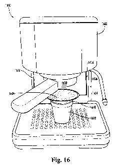
100821 Fig. 16 is side plan view of an embodiment of'a low-cholesterol
espresso
dispenser 1600. The low-cholesterol espresso dispenser 1600 generally may
inckude an
espresso brewing system 1602 and at least one filter 1604. The espresso
brewing
system 1602 may be configured to brew espresso at a relatively high pressure.
'Ihe
filter 1604 may be configured to filter the espresso at a relatively low
pressure after the
espresso is brewed. The relatively low pressure ensures at least sonte of the
high-
cholesterol oils in the espresso are retained by the filter 1604 instead of
being #orced
through the filter 1604.
[0083] `I'he espresso brewing system 1602 can be any system that brews
espresso at a
relatively high pressure. More specifically, the espresso brewing system 1602
has a high-
pressure brewing area 1606 in which cofJee beans and water interact. "f'he
relatively high
pressure in the high-pressure brewing area 1606 causes the solids and oils to
be extracted
from the coffee beans and to be dispersed throughout the water. 'l'hus,
espresso is created.
For purposes of this disclosure, the term "high pressure" generally denotes a
pressure
above atmospheric pressure that is suited for extracting solids and oils frotn
coffee beans.
T'he higlt pressure may be a pressure of about 3 bars to about 15 bai-s or
higher, depending
on the cmbodiment.
100841 The espresso brewing system 1602 inay be any type of conventional
espresso
machine, including a super-automatic espresso machine, an automatic espresso
machine, a
semi-automatic espresso machine, a manual espresso machine, a stove-top
espresso maker.
and similar types o1' devices. "I'ypically, conventional espresso machines
en7ploy a high
pressure between about 9 bars and about 10 bars within a brewing area 1608. As
shown in
Fig. 16, the espresso brewing system 1602 may be a semi-automatic espresso
niachine,
and the brewing area 1608 may be a conventional portafilter. The portafilter
may be
similar to that described in commonly-owned U.S. Patent Application Serial No.
11/160,531, filed ort June 28, 2005.
[00851 Alternatively, the espresso brewing system 1602 may be an embodiment of
the
beverage dispenser systern 100 described above with reference to Figs. 1- 14.
In such case,
the beverage dispenser system 100 entploys a pod cartridge 1710. `l'he pod
cartridge 1710
is described below with reference to Figs. 17-19. The pod cartridge 1710 may
have a
CA 02695284 2010-02-01
WO 2009/017927 PCT/US2008/068902
18
brewing area 1718, and the beverage dispenser system 100 employs a high
pressure of
about I I bars within the brewing area 1718. In still other embodiments, other
espresso
brewing systems 1602 can be used. Additionally, other high pressures can be
employed to
vary the flavor and consistency of the resulting espresso.
[0086 j"The high-pressure brewing area 1606 of the espresso brewing system
1602 rnay
have an exit 1610. Once the espresso is brewed, the espresso travels from the
high-
pressure brewing area 1606 through the exit 1610 and into a container 1612,
such as the
cup 230 described above. The container 1612 receives the espresso from the
exit 1610
and holds the espresso at about atmospheric pressure so that the espresso can
be
consumed, A relatively low-pressure area 1614 is formed between the exit 1610
of the
high-pressure brewing area 1606 and the container 1612. The espresso passes
through the
low-pressure area 1614 after exiting the high-pressure brewing area 1606 and
before
entering the container 1612. For the purposes of this disclosure, the tenn
"low pressure"
generally denotes a pressure that is relatively lower than the high pressure
used to brew the
espresso.
[0087] For example, the low-pressure area 1614 may be an area between the high-
pressure area brewing area 1606 and the container 1612 that is exposed to the
atmosphere.
In such cases and in other cases, the low pressure in the low-pressure area
1614 may be
about atmospheric pressure. The espresso may move through the low-pressure
area 1614
under the force of gravity. In the einbodiment shown in Fig. 16, the espresso
descends
from the brewing area 1608, through the low-pressure area 1614, and into the
container 1612 under the force of gravity. In the embodiment shown in Figs. 17-
19, the
espresso descends from a brewing area 1718 of the pod cartridge 1710, through
the low-
pressure area 1614, and into the container 1612 under the force of gravity. In
other
embodiments, the espresso may be moved through the low-pressure area 1614
under a
pressure that exceeds the force of gravity yet is relatively lower than the
pressure in the
high-pressure brewing area 1606.
[0088] To form the low-cholesterol espresso dispenser 1600, at least one
filter 1604 is
position about the low-pressure area 1614 of the espresso brewing system 1602.
"The
filter 1604 is configured to reniove high-cholesterol oils from the espresso.
Because the
filter 1604 is positiioned in the low-pressure area 1614, the fi lter 1604 can
capture at least
some of the high-cholesterol oils that would he forced through the filter 1604
at high
CA 02695284 2010-02-01
WO 2009/017927 PCT/US2008/068902
19
pressure. Therefore, the cholesterol content of the espresso may be reduced.
Although
only one filter 1604 is shown, additional filters 1604 may be employed as
desired.
[0089J More specifically, the filter 1604 may be positioned anywhere in the
low-
pressure area 1614. In some embodiments, the filter 1604 may be positioned
adjacent the
exit 1610 of the high-pressure brewing area 1606_ For example, the filter 1604
may be
positioned within the pod cartridge 1710, as described below with reference to
Figs. Ã 7-
19. In other embodiments, the filter 1604 may be positioned somewhere between
the exit
1610 of the high-pressure brewing area 1606 and an entrance 1618 into the
container
1612. Such positioning is shown in Fig. 16. As shown, the filter 1604 tnay be
positioned
on suspension arms 1616 that hang downward from the espresso brewing svstem
1602. In
still other embodiments, the filter 1604 may be positioned adjacent the
entrance 1618 into
the container 1612. For example, the filtcr 1604 may be a permanent filter
that is rested
on the entrance 1618 of the container 1612 betore the espresso is brewed, and
is set aside
for future use after the espresso is brewed. 't'he filter 1604 also may be a
disposable
filter 1604 that is coupled to the entrance 1618 ofthe container 1612 before
the espresso is
brewed, and is detached and discarded after the espresso is brewed. In
embodinients irt
which the filter 1604 is positioned soinewhere between the exit 1610 of the
high-pressure
brewing area 1606 and the entrance 1618 into the container 1612, or in cases
in which the
filter 1604 is positioned adjacent the entrance 1618, the filter 1604 may
liave a concavity.
'I'he concavity may enable the espresso to accumulate above the lilter 1604.
For example,
the espresso may descend at a rate that exceeds the rate at which the espresso
can pass
through the filter 1604. In such cases, the concavity provides an area where
the espresso
can accumulate betore passing through the filter 1604.
[0090] Any filter 1604 having a porosity and a inaterial suited to remove at
least some of
the high-cholesterol oils from the espresso can be used. For example, the
filter 1604 may
be formed from a paper material, a cloth material, a metallic material, a
ceramic material.
or any other material or conibination thereof. '1'he material of the filter
1604 may be suited
to separate the high-cholesterol oils from the espresso. In some embodiments,
the
filter 1604 may he formed from a material having an affinity for high-
cholesterol oils so
that the high-cholesterol oiÃs are attracted to the filter 1604. In some
embodiments, the
filter 1604 may be configured to remove at least some of the terpenes from the
espresso,
CA 02695284 2010-02-01
WO 2009/017927 PCT[US2008/068902
so that the LDL cholesterol content of the espresso is reduced. In such
embodiments, the
filter 1604 has a porosity selected to remove at least some of the terpenes.
10091] The filter 1604 may be disposable or permanent, depending on the
embodiment.
Filters 1604 that are disposable may be used one time or a few times before
being
5 replaced. Filters 1604 that are permanent may be permanently integrated into
the espresso
brewing system 1602. Such filters 1604 also may be removably integrated into
the
espresso brewing system 1602, so that espresso can be brewed without removing
the high-
cholesterol oils when desired.
[0092] Figs. 17 aind 18 are perspective views of an embodiment of a pod
cartridge 1710.
10 Fig. 19 is a cross-sectional view of the pod cartridge 1710 taken along
line 19-19. The
pod cartridge 1710 may be an embodiment of the pod cartridge 210, which is
generally
described above with reference to Figs. 6-14, The pod cartridge 1710 may be
used with
the beverage dispenser system 100, which is generally described above with
reference to
Figs. 1-5.
15 [0093] Like the pod cartridge 210, the pod cartridge 1710 may be configured
for
brewing espresso at a relatively high pressure. !n addition, however, the pod
cartridge 1710 may include the filter 1604 configured to remove at least some
high-
cholesterol oils from the espresso at relatively low pressure.
[0094] More sp"ifically, the pod cartridge 1710 may include the sidewall 1712
and the
20 base 1714, The sidewall 1712 defines an interior space 1716. The base 1714
separates the
interior space 1716 into a brewing area 1718 and an accumulation area 1720.
The brewing
area 1718 may be the high-pressure brewing area 1606 where the coffee beans
and water
interact. The accumulation area 1720 may be the low-pressure area 1614 where
the
cspresso is filtered.
[0095] More specifically, the brewing material 550 and the filter paper 850
may be
placed in the brewing area 1718, as described above, The base 1714 has
apertures 1722
that form the exit 1610 from the brewing area 1718 into the accumulation area
1720. The
filter 1604 may be positioned at an end 1724 of the accumulation area 1720
opposite from
the base 1714. The accumulation area 1720 is sized to allow the espresso to
accumulate in
the accumulation area 1720 at a relatively low pressure. Therefore, the
pressure of the
espresso is reduced before the espresso reaches the filter 1604. The espresso
then passes
CA 02695284 2010-02-01
WO 2009/017927 PCT/US2008/068902
21
through the filter 1604 when exiting the accumulation area 1720, so that at
least some ol'
the high-cholesterol oils in the espresso are captured.
100961 More specifically, the injector assembly 400 begins forcing water
through the
brewing arca 1718 when the brewing process begins. '1'he freshly-brewed
espresso begins
flowing into the accumulation area 1720 through the apertures 1722 and out of
the
accumulation area 1720 through the filter 1604. The flow rate of the espresso
into the
accumulation area 1720 may exceed the flow rate of the espresso out of the
accutnulation
area 1720 because the filter 1604 tends to impede the espresso. Therefore, the
espresso
may accumulate in the accumulation area 1720. However, the sizing of the
accumulation
area 1720 ensures the espresso is under relatively lower pressure in the
accumulation
area 1720 than in the brewing area 1718. Otherwise, if the accumulation area
1720 is too
small, the espresso may be subjected to a hackpressure that forces the high-
cholesterol oils
through the filter 1604. For example, the accumulation area 1720 may have a
volume
selected so that the volurne ol'the accumufation area 1720 exceeds a volume of
espresso in
the accumulation area 1720 at any point in the brewing process. "The espresso
can then
accumulate freely at a relatively low pressure, such as atmospheric pressure.
[0097] The sizing of the accumulation area 1720 may be adjusted based on the
con6guration of the apertures 1722 and the f ilter 1604. More specitically,
the (low rate
into the accumulation area 1720 may be determined by the apertures 1722 while
the flow
rate out of the accumulation area 1720 may be determined by the filter 1604.
However,
the apertures 1722 and the filter 1604 arc not primarily configured to achieve
the desired
flow rate. Instead, the apertures 1722 are primarily configured to achieve an
appropriate
high pressure in the brewing area 1718, while the filter 1604 is primarily
configured to
provide the appropriate filtration of high-cholesterol oils. For example, the
apertures 1722
may have a certain size, number, and distribution across the base 1714 while
the
filter 1604 may have a certain porosity. Because the apertures 1722 and the
tiltcr 1604
have configurations selected for reasons other than achieving the desired flow
rate, the
sizing of the accumulation area 1720 may be adjusted.
(00981 As shown in Fig. 19, the sidewall 1712 ol'the pod cartridge 1710 may be
extended in contparison with the sidewall ofthe pod cartridgc 210 shown in
Fig. 8.
Extending the sidewall 1712 increase the volume of the accumulation area 1720.
For
example, the sidewall 1712 may be extended so that the espresso freely
descends into the
CA 02695284 2010-02-01
WO 2009/017927 PCT/US2008/068902
22
accutnulation area 1720 and returns to about atmospheric pressure before being
filtered.
In such cases, the beverage dispenser system 100 may include a turret assembly
310
having pod apertures 1722 that can accommodate the pod cartridge 1710 with the
extended sidewall 1712. The support ribs on the pod cartridge 1710 may or may
not be
extended in such cases.
100991 In the illustrated embodiment, the pod cartridge 1710 may be
disposable. In such
embodiments, the i:ilter 1604 may be a disposable material such as paper. The
filter 1604
may be coupled to an interior surface of the sidewall 1712 adjacent a lower
edge below the
support ribs. For example, the filter 1604 may be welded to the sidewall 1712.
For the
purposes of this disclosure, the term "welded" generally denotes the filter
1604 is secured
to the sidewall 1712 by applying heat where the filter 1604 and the sidewall
1712
intersect. The heat causes the materials used to forin the filter 1604 and the
sidewall 1712
to commingle, forrning a secure connection. In other embodiments, the filter
1604 may be
attached at other positions or in other manners.
[0100] The low-cholesterol espresso dispenser 1600 may be conf-igured to brew
both
regular espresso and low-cholesterol espresso. For example, the beverage
dispenser
system 100 may be configured for use with both the pod cartridge 210 and the
pod
cartridge 1710 having the filter 1604. A user wishing to drink regular
espresso may select
the pod cartridge 210 while a user wishing to drink low-cholesterol espresso
may select
the pod cartridge 1710. The user may make the selection via a button or
control on the
low-cholesterol espresso dispenser 1600. The user may be influenced not only
by health
requirements but also by taste, as filtered espresso may have a different
taste than
unfiltered espresso.
101011 '1'he low-cholesterol espresso dispenser 1600 may be fiirther
configured to
incorporate the espresso into an espresso-based beverage. Espresso-based
beverages are
coffee beverages rnade by extracting espresso under high pressure and
subsequently
mixing the espresso with other liquid, such as water, milk, or chocolate.
Example
espresso-based coffee beverages include Americano, cappuccino, latte, and
mocha, among
others. In such enibodiments, the low-cholesterol espresso dispenser 1600 may
filter the
espresso before or after the espresso is mixed with the other liquids. For
example, in Fig.
16 the espresso brewing system 1602 may mix the espresso with other liquids
and the
CA 02695284 2010-02-01
WO 2009/017927 P('T/US20(18/068902
2 33
resulting espresso-based beverage may then pass through the filter 1604 into
the
container 1612.
10102J Fig. 20 is a block diagram iliustrating an embodiment of a niethod of
making
relatively low-cholesterol espresso and espresso-based beverages. In block
2002, the
espresso is brewed under a relatively high pressure, such as a high pressure
in the range of
about 3 bars to about 15 bars. For example, a high pressure of about 9 bars to
about 10
bars may be used to brew the espresso in a conventional espresso machine, or a
high
pressure of about 1 i bars may be used to brew the espresso using the beverage
dispenser
system 100. In block 2004, the pressure of the espresso is reduced to a
relatively low
pressure. The low pressurc is relatively lower than the high pressure used to
extract the
espresso and may be atmospheric pressure. The pressure ot'the espresso may be
reduced
to the low pressure by allowing the espresso to descend from a high-pressure
brewing area
into a low-pressure area, such as an area at at-nospheric pressure. For
example, the
pressure of the espresso mav be reduced to the low pressure by allowing the
espresso to
descend from the high pressure brewing area into an accumulation area of a pod
cartridge.
In block 2006, the espresso is filtered at the relatively low pressure to
remove at least
some ofthe high-cholesterol oils from the espresso. Filtering the espresso at
the relatively
low pressure allows at least some of the high-cholesterol oils to be removed
from the
espresso. For example, the espresso may be filtered by allowing the espresso
to descend
through a filter.
101031 In some embodiments, the espresso may be mixed with one or more other
liquids
to forni an espresso-based beverage in block 2008. For example, the espresso
may be
mixed with water to form Americano, or milk to form cappuccino. It should be
noted that
the espresso is filtered in block 2006 after the espresso is brewed in block
2002 and the
pressure is reduced in block 2004, flowever, the espresso may be mixed with
other liquids
in block 2008 either before or after the pressure is reduced in block 2004 and
the espresso
is filtered in block 2006.