Note: Descriptions are shown in the official language in which they were submitted.
CA 02695824 2010-02-08
Verification of SecuritX Elements Having Windows
The present invention relates to a method and an apparatus for verifying
value documents, such as banknotes, identification cards, payment cards,
admission tickets, drawing tickets or the like that exhibit a substrate having
at least one light-transmitting region, a first piece of information being
arranged in at least one light-transmitting region of the substrate. The
present invention further relates to a method and an apparatus for verifying
or for examining valuable articles that exhibit a display, for example a
computer, notebook or laptop, a cash register in a cash register system or a
handheld device.
Light-transmitting regions in security documents, such as windows, are
becoming increasingly attractive. There are, for example, already different
functionalities for a window in which pieces of information included in the
banknote are made visible through a self-verification in that, for example,
the
banknote is held alternatingly over a white and black background, or is lit
with a laser pointer through the window.
For example, publication WO 2006/018171 Al describes a security element
whose transparent or translucent substrate is provided with an
authenticating mark. Here, a phase-shifting layer and a linearly polarizing
layer are applied on a transparent foil, the main axis of the phase-shifting
layer being rotated by at least 10 against the polarization direction of the
linearly polarizing layer. The phase-shifting layer is formed from a
birefringent or an optically active material, such as a liquid crystal
material,
for example in the nematic or smectic phase. In transmitted light, this
authenticating mark conveys a first optical impression, and in reflected light
against a predetermined and easily accessible background, a second optical
impression that differs significantly from the first optical impression. This
CA 02695824 2010-02-08
-2-
facilitates a simple and quick authenticity check in which the security
element is first viewed in transmitted light and is then held against a
predetermined background.
The solutions in the background art make it possible for a certain
authenticating mark to be perceptible, but a temporary exchange of the
stored information, for example a monthly exchange of information, is not
possible.
It is thus the object of the present invention to develop an authenticity
check
of security elements in such a way that the counterfeit protection is further
increased and a temporary exchange of hidden pieces of information is made
possible.
This object is solved by the features of the independent claims.
Developments of the present invention are the subject of the dependent
claims.
In this context, the present invention comprises a method and an apparatus
for verifying value documents, such as banknotes, securities, credit, debit or
identification cards, passports, certificates, admission tickets, drawing
tickets
and the like, labels, packaging or other elements for product protection.
Here, a first piece of information is arranged in at least one light-
transmitting
region of a security element. According to the present invention, a separate
display, for example a screen of a computer, notebook or laptop, a monitor of
a cash register in a cash register system, or a display of a handheld device,
displays, at least in some regions, a second piece of information. Either in
the
first or the second piece of information, or also in both pieces of
information,
is hidden a further piece of information that is not, or is only hardly,
CA 02695824 2010-02-08
-3-
perceptible and,/or readable for a viewer without auxiliary means.
According to the present invention, a verification of the security element
occurs in that the first piece of information in the translucent region of the
security element is laid over the second piece of information and the hidden
piece of information becomes perceptible and/or readable as a moire pattern
and/or as a metamerism.
A particular advantage of the present invention is that the hidden piece of
information includes, for example, the emission value or the currency of a
banknote and can thus serve as an authenticity examination at a cash register
terminal. Here, the banknote is laid over the display of the cash register
terminal and the information hidden on the banknote shows up in clear
lettering for the cash register personnel.
The present invention further comprises a method and an apparatus for
verifying or for examining valuable articles that exhibit a display, for
example a computer, notebook or laptop, a cash register in a cash register
system, or a handheld device. Here, according to the present invention, a
separate verification element is used that exhibits at least one substrate
having at least one light-transmitting region, a first piece of information
being arranged in at least one light-transmitting region of the substrate.
Furthermore, through the display, a second piece of information is displayed
at least in some regions. In the first and/or second piece of information, a
further piece of information is hidden that is not perceptible and/or readable
for a viewer without auxiliary means. According to the present invention, a
verification or examination of the valuable article occurs in that the
verification element with its first piece of information is laid over the
second
piece of information and, in transmitted light, the hidden piece of
CA 02695824 2010-02-08
-4-
information becomes perceptible and/or readable as a moire pattern and/or
as a metamerism.
A particular advantage here is that the hidden piece of information includes,
for example, the name of the owner of the valuable article, and can thus
serve as a proof of ownership in the event of theft or loss of the valuable
article. Here, the verification element is laid over the display of the
valuable
article and the piece of information hidden on the display shows up in clear
lettering for the viewer, for example an investigating authority.
A display that can depict different pieces of information in alternation, or
also no information, is preferably an active display having its own
illumination source that illuminates the display from the back. Likewise, the
display can also be a passive display without its own illumination source, a
reflective surface that is arranged on the back of the display reflecting
daylight or ambient light and thus illuminating the display indirectly. The
present invention is preferably also applicable on a novel transparent display
whose base body is perceived by a viewer as (nearly) transparent. The
transparent display itself acts here as a (nearly) transparent window and the
pieces of information depicted on the transparent display are depicted as a
single- or multicolored clouding of the window that influences or weakens
the light passing through the transparent display.
The handheld device is, for example, a mobile phone, or cell, a digital
camera, digital clock, a credit card or an identification document, for
example a passport or an identification card, having a display or a portable
playback device for video or audio signals, such as an mp3 player or an I-
pod from App1e .
CA 02695824 2010-02-08
-5-
Within the meaning of the present invention, a piece of information is not, or
is only hardly, perceptible whenever a viewer does not see or perceive it
from the surrounding information without auxiliary means, or does so only
by chance and weakly pronounced. In the same spirit, a piece of information
is not, or is only hardly, readable whenever a viewer does not see the
alphanumeric or textual content of the information from the surrounding
information without auxiliary means, or does so only by chance and weakly
pronounced, or cannot read or interpret it correctly.
Within the meaning of the present invention, a moire pattern is an optical
appearance that can be observed upon transillumination of two stacked line-
shaped or punctiform grids with a parallel or nearly parallel light beam.
Here, a uniform or non-uniform distribution of basic pattern elements at
least in one region of the substrate and of the display is defined as the
grid,
the basic pattern elements being spaced apart. Basic pattern elements here
are preferably lines, that is, elements whose width is significantly smaller
than their length, and that are formed to be straight, wavy or bent, or
exhibit
a combination of these three embodiment types, or punctiform elements
whose width is approximately the same as their length, such as points,
circles or squares. If two grids that, for example, can be structured to be
nearly uniform, are laid one on top of the other, then the superimposition
results in light spots in certain regions and dark spots in other regions, the
so-called moire pattern.
The line-shaped or punctiform grid is preferably
- imprinted on the security element or the verification element from a
single- or multicolored lacquer layer and/or adhesive layer, or
- embossed in the substrate of the security element or of the verification
element, or
CA 02695824 2010-02-08
-6-
- produced through laser inscription of a substrate by means of measures
known from the background art, such as color coupler systems in the
presence of an IR absorber that is coordinated with the laser wavelength,
or
- produced through ablation from a contiguously applied coating.
In the latter case, the contiguously applied coating preferably consists of a
metal layer and the ablation occurs through a partial demetallization of the
metal layer. Here, a mechanical scraping, a laser ablation, a washing process
or other methods known in the background art may be used as the
demetallization. The contiguous coating can consist of an ink based on
pigments or dyes. A partial ablation or sublimation of the pigments or dyes
occurs through evaporation by means of laser radiation. The coating can
additionally contain IR absorbers, coordinated with the wavelength of the
laser radiation, to support the process.
Here, preferably, also an individualization of the hidden piece of information
is possible. In this way, an arbitrary individual piece of information, such
as
a serial number of a banknote or the name of the owner of the display, can be
introduced into the line-shaped grid. This occurs, for example, in that the
arbitrary individual piece of information is introduced into a metal layer
with a demetatlization.
Furthermore, the grid is preferably applied on the light-transmitting region
of the valuable article or of the verification element from opacifying or
opaque inks. This has the advantage that the contrast of the moire pattern is
increased by this.
CA 02695824 2010-02-08
-7-
In addition, the grid can be applied on the light-transmitting region of the
valuable article or of the verification element on both sides of the light-
transmitting region, that is, double-sided. Here, in each case, one grid is
applied both on the front and on the reverse of the light-transmitting region,
with the grid on the reverse of the light-transmitting region lying exactly
opposite the grid on the front. In this way, if one looks at the light-
transmitting region vertically, the two grids are superimposed such that,
particularly advantageously, the hiding power of the grid is enhanced and
the visibility of the moire pattern thus increased.
Alternatively, the line-shaped or punctiform grid is also produced from a
lacquer and/or adhesive layer that is not, or is only hardly, visually
visible.
If, for example, an adhesive is applied in a pattern via a printing process,
moire patterns likewise result through a scattering of the light at the
produced adhesive layer.
If the lacquer and/or adhesive layer of the grid is preferably produced
through opacifying pigments and/or opacifying fillers such as Ti02, then the
lacquer and/or adhesive layer is not, or is only hardly, visually visible in
top
view. When looked through, that is, against a background having an
identical or similar color as the grid, the grid becomes visible or
perceptible.
In a further embodiment, the first piece of information of the light-
transmitting region is produced by means of a blind embossing of the
transparent region of the substrate.
In a preferred embodiment, the valuable article or the verification element
consists of a card, composed of at least two laminated substrates, that
CA 02695824 2010-02-08
-8-
exhibits at least one light-transmitting region. Here, the grid is applied in
or
on at least one of the light-transmitting regions of the card, wherein
- the grid is first applied to a light-transmitting substrate and the card
subsequently laminated or
- the card is first laminated and the grid subsequently introduced into the
laminate of the card, for example by means of laser radiation.
If the valuable article or the verification element consists of a value
document, for example a banknote, having a transparent foil element over a
window region, then the foil element to be applied can already include the
grid and appropriate overprints, for example transparent, optically variable
colors. Alternatively, the foil element can exhibit no or also only individual
intermediate steps, such as only the grid or only transparent, optically
variable colors, that are completed after application to the valuable article
or
the verification element.
In the case of a foil-based substrate having opacifying and non-opacifying
regions, a separate foil element is not required. In this case, the grid and
appropriate overprints are applied directly to the non-opacifying region of
the substrate.
A moire pattern likewise results when a grid composed of scattering
elements composed of blind embossings or optical lenses is applied to the
light-transmitting region of the security element or of the verification
element. A piece of microinformation that is not visually visible and is
coordinated with the lens embossing is depicted on the display. Especially
magnification effects occur here, the piece of microinformation being
depicted multiply magnified by the superimposition with the lens grid. For
example, a microtext that is pictured on the display and that is not
CA 02695824 2010-02-08
-9-
perceptible or readable for a viewer is magnified by the superimposition
with an appropriate lens grid in such a way that it is easily readable for the
viewer.
Within the meaning of the present invention, metamerism is a color disparity
that occurs upon changing the type of light or the wavelength range of
electromagnetic radiation. Two metameric inks thus appear uniform in a first
wavelength range, but exhibit a different color impression in a second
wavelength range. The first and second wavelength range here can be
completely different or exhibit a certain overlap region. Metameric ink pairs
are also referred to as conditionally identical.
Here, the metameric inks or the metameric ink pairs exhibit a comparable
transparency, and if possible, include no opacifying pigments andJor
opacifying fillers such as Ti02, that is, they are transparent.
In a preferred embodiment, in a first wavelength range, preferably in
daylight or a similar artificial lighting, at least two metameric inks produce
an identical color impression. Through the display, as a second piece of
information, light is now emitted in at least a second wavelength range at
which the at least two metameric inks produce at least two different color
impressions.
Alternatively, in the first wavelength range, the at least two metameric inks
produce at least two different color impressions. In this case, through the
displav is emitted, as a second piece of information, light in at least a
second
wavelength range at which the at least two metameric inks produce an
identical color impression.
CA 02695824 2010-02-08
-10-
If, in both cases, the display alternatingly emits light of different
wavelengths as a second piece of information, then a viewer perceives a
switch between a uniformly colored area and an area composed of different
colored sub-areas. This alternation preferably occurs in a chronological
sequence. For example, the display emits light of a first wavelength range
one second long, and thereafter, light of a second wavelength range one
second long, after which the sequence repeats regularly.
However, hybrid forms of moire patterns and metamerism are also possible.
For example, the basic pattern elements of the line-shaped or punctiform
grid can be imprinted from metameric inks such that, in one region, a hidden
piece of information can be decoded with the aid of the moire effect, and a
further hidden piece of information with the aid of the metamerism. In this
way, multiple different pieces of information can be hidden in one region.
Furthermore, the first, second or the hidden piece of information can be
executed to be single- or multicolored. Here, the basic pattern elements of a
line-shaped or punctiform grid are preferably executed to be multicolored
such that not only the usual light/ dark moire effect is created, but rather,
through color mixing, also different colors or color gradations are possible.
Within the meaning of the present invention, a light-transmitting substrate is
a substrate that allows impinging light to pass through in a certain
proportion. If light impinges on one side of the substrate, a certain
proportion of the light is passed through to the other side of the substrate
and exits again there. The larger the percentage proportion of light passing
through in relation to the impinging light, the more light-transmitting the
substrate is. If the percentage proportion is at least 90%, that is, if, as
with a
window, the substrate allows the impinging light to pass through nearly
CA 02695824 2010-02-08
-11-
unattenuated, the substrate is referred to as transparent. If a proportion of
less than 90% of the impinging light, preferably between 80 and 20%, passes
through the substrate, the substrate is referred to as translucent. In
contrast,
a substrate that allows less than 20%, preferably below 10% and particularly
preferably about 0% of the impinging light to pass through, that is, in which
the proportion of light passing through in relation to the impinging light is
low or near or equal to zero, is referred to as opaque or as non-light-
transmitting.
Particularly advantageously, the light-transmitting region of the substrate of
the security element or of the verification element is a transparent or
translucent plastic foil that is executed to be single- or multilayer, or a
transparent or translucent region within an otherwise opaque substrate, such
as a card body or a paper.
The further piece of information that is not, or is only hardly, perceptible
and/or readable for a viewer without auxiliary means is hidden either in the
first or the second piece of information, or also in both pieces of
information.
If the hidden piece of information is located at least partially within the
first
piece of information, that is, on or in the substrate, then, through
superimposition with the second piece of information, either the entire
hidden piece of information becomes visible or readable, or only a portion of
the hidden piece of information. If only a portion of the hidden piece of
information becomes visible, then, by displacing the second piece of
information, further portions of the hidden piece of information can become
visible such that the uncovered portion of the hidden piece of information
moves over the light-transmitting region of the substrate.
CA 02695824 2010-02-08
-12-
If, in contrast, the hidden piece of information is located at least partially
within the second piece of information and thus on the display, then the first
piece of information serves as a decoder, that is, the hidden piece of
information becomes visible or readable through superimposition with the
first piece of information. Here, it is possible to depict on the display
arbitrary second pieces of information that are coordinated with the first
piece of information such that, also in a certain region, either static or
different, varying or film-like-playing pieces of information are depictable
that, however, are not visible or readable without the first piece of
information. Preferably also sequences of color changes of the metameric
inks or wandering dark and light regions of the moire pattern can be
depicted here.
The hidden piece of information can also be located within the first and the
second piece of information. Here, the first piece of information is broken
down into two or more sub-areas on the security element or the verification
element, where a sub-area includes the information to be verified. The
second portion to be verified is depicted in the display and is arranged in
such a way that it is located next to the first portion to be verified and
does
not overlap therewith or does so only marginally.
In a preferred embodiment of the present invention, the at least one light-
transmitting region of the substrate is combined with a transparent or at
least translucent further security feature. Here, this further security
feature is
executed such that the inventive hidden piece of information that is not
perceptible and/or readable for a viewer without auxiliary means is not
disrupted and thus continues to be perceptible.
CA 02695824 2010-02-08
-13-
This further security feature consists especially of an ink having
interference
pigments or liquid crystals, or of an optically variable thin-film layer, as
is
known, for example, from WO 2005/108110. Here, an optically variable ink
having interference pigments is, for example, an ink having optically
variable pigments that exhibit at least one interference-capable, multilayer
structure, as is known, for example, from DE 10 2006 062 281. As explained
in DE 10 2006 062 281, these optically variable pigments can be altered with a
laser in such a way that, as an additional effect, another appearance results
in
transmitted light than in reflected light. A further example of an optically
variable ink is a so-called Iriodin ink.
An ink having liquid crystals or pigments composed of liquid crystals is
known, for example, from WO 2006/018171 A2, cited in the introduction to
this description. It has especially the property of exhibiting another
appearance or another color in front of a dark or black background than in
front of a light or white background. Furthermore, it has the property that,
regardless of the background, at a certain viewing angle or angle range, the
so-called glancing angle, it appears in a certain color, and at another
viewing
angle or angle range, does not appear.
The further security feature can be areal or patterned, for example an areal
pattern.
Furthermore, the further security feature can be executed such that it can be
perceived with a certain auxiliary means, in the case of ink having liquid
crystals or pigments composed of liquid crystals, for example, with the aid of
a polarizing filter.
CA 02695824 2010-02-08
-14-
Particularly preferably, the further security feature correlates with the
inventive piece of information that is hidden and not perceptible and/or
readable for a viewer without auxiliary means. In this way, the inventive
hidden piece of information can depict, for example, the number "50" and the
further security feature the lettering "EURO".
Furthermore, the further security feature and the inventive hidden piece of
information can complement each other. For example, the further security
feature depicts the lettering "EU" and the inventive hidden piece of
information the lettering "RO" and thus together "EURO".
Alternatively, the inventive hidden piece of information is called up at the
same time as the further security feature by tilting, in that the substrate
having the at least one light-transmitting region is tilted. Likewise, the
inventive hidden piece of information can be verified as a complement at the
same time as the further security feature by applying a polarizing filter to
the
print pattern.
If the light-transmitting region of the substrate of the security element or
of
the verification element is a transparent or translucent plastic foil, the
plastic
foil can additionally be developed as a polarizing filter. A contrast
enhancement of the uncovered hidden piece of information preferably
results in the form of the moire pattern or the metamerism.
In addition, also the light-transmitting region of the substrate can exhibit a
polarizing effect.
The uploading of the appropriate current second piece of information to the
display or to the electronics that control the display occurs via the
Internet,
CA 02695824 2010-02-08
-15-
by e-mail, in the case of mobile phones also as an SMS, or via removable
storage media such as memory cards, flash cards or CDs/DVDs.
A preferred application of the present invention results, for example, when
proving the ownership of a mobile device, such as a mobile phone. On an
identification card as a verification element, a first piece of information is
depicted in a light-transmitting region, and an image having a second piece
of information is displayed on the mobile phone. If the owner of the mobile
phone now lays the identification card over the display of the mobile phone,
a hidden piece of information becomes visible that includes, for example, the
name of the owner. In a first alternative possibility here, the hidden piece
of
information is located in the first piece of information on the identification
card, which must be executed to be personalized to the owner therewith. In
the second possibility, the hidden piece of information is located on the
display of the mobile phone, the identification card being, for example,
identical for all owners of mobile phones of the associated network operator
or the associated manufacturer of the mobile phone. Here, the hidden piece
of information is particularly preferably stored on the SIM card of the owner
or is produced according to a certain method via the personalized SIM card.
A further preferred application relates to drawing tickets having a win
functionality, on which a light-transmitting region, especially a window
having a first piece of information, is located. The owner of the drawing
ticket is sent, for example via SMS or via e-mail, a second piece of
information that he can display on the display of a mobile phone or a
computer. The owner now holds the drawing ticket over the display and
immediately establishes whether the drawing ticket is a winner or a blank.
Here, both possibilities exist, that the hidden piece of information is
located,
on the one hand, in the drawing ticket itself, or on the other hand, in the
CA 02695824 2010-02-08
-16-
second piece of information transmitted by SMS or e-mail. In the first case,
the owner sends the drawing ticket to the initiator of the contest as proof,
and in the second case, the proof is provided via the personalized SMS or e-
mail.
The advantages of the present invention will be explained with reference to
the following examples and supplementing drawings. The individual
features described and the exemplary embodiments described below are
inventive in themselves, but are also inventive in combination. The examples
depict preferred embodiments, to which, however, the present invention is
in no way intended to be limited. The proportions shown in the figures do
not correspond to the actual ratios and serve solely to improve clarity.
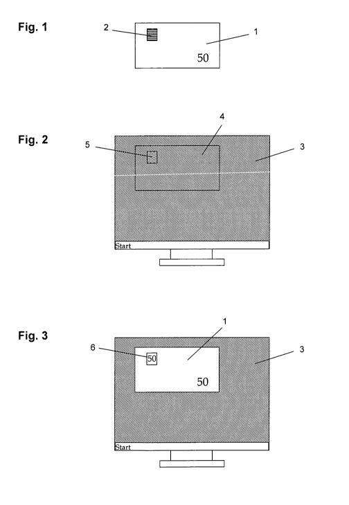
In detail, depicted schematically are:
Fig. 1 a banknote having a window and grid having a first piece of
information, in top view and/or when looked through,
Fig. 2 a screen having a grid having a second piece of information, in top
view,
Fig. 3 the screen from fig. 2 and the banknote from fig. 1, one on top of the
other,
Fig. 4 a cell display having a grid having a second piece of information, in
top view,
Fig. 5 the cell display from fig. 4 and the banknote from fig. 1, one on top
of the other,
CA 02695824 2010-02-08
-17-
Fig. 6 a banknote having a window and two hidden pieces of information
composed of a moire pattern and a metamerism within a first piece
of information, in top view, or top view and when looked through,
Fig. 7 the screen from fig. 2 and the banknote from fig. 6, one on top of the
other,
Fig. 8 an areal geometry for a metameric ink pair, in top view,
Fig. 9 a screened geometry for a metameric ink pair, in top view,
Fig. 10 a valuable article or a verification element composed of a substrate
having a light-transmitting region and a first piece of information
arranged in the shape of a grid on the front, in side view,
Fig. 11 the valuable article or the verification element from fig. 10 having a
grid on the reverse, exactly opposite the grid on the front,
Fig. 12 the valuable article or the verification element from fig. 10, on the
front, partially overprinted with an optically variable ink,
Fig. 13 the valuable article or the verification element from fig. 12 having a
further optically variable ink on the reverse,
Fig. 14 the valuable article or the verification element from fig. 11 on the
front and reverse, each partially overprinted with an optically
variable ink,
CA 02695824 2010-02-08
-18-
Fig. 15 the valuable article or the verification element from fig. 12 having a
portion of the grid composed of lithopone and a portion composed
of an opacifying black ink,
Fig. 16 the valuable article or the verification element from fig. 15,
additionally on the reverse having a grid composed of lithopone and
a portion composed of an opacifying black ink, overprinted with the
optically variable ink,
Fig. 17 the valuable article or the verification element from fig. 15, but
having two different optically variable inks,
Fig. 18 the valuable article or the verification element from fig. 15 having a
grid composed of an opacifying chromatic ink on the reverse,
Fig. 19 the valuable article or the verification element from fig. 10, the
grid
consisting of three-laver thin-film elements,
Fig. 20 one of the valuable articles or verification elements from fig. 15 to
18,
in top view from the front or reverse, the lines of the grid for
lithopone and for the black ink being executed to be joint to joint,
Fig. 21 one of the valuable articles or verification elements from fig. 16 and
17, in top view from the opposing side with respect to fig. 20, the
lines of the grid for lithopone and for the black ink being executed to
be joint to joint.
Examples of different preferred embodiments of the present invention are
explained in the following with reference to the figures. For the sake of
better
CA 02695824 2010-02-08
-19-
comprehensibility, the illustrations in the figures are highly schematized and
do not reflect the real conditions. For this, for the sake of better
comprehensibility, the described embodiments are reduced to the essential
core information. In practical implementation, significantly more complex
patterns or images in single- or multicolor printing can be used. The pieces
of information depicted in the following examples can likewise be replaced
by any complex pieces of image or text information.
The different exemplary embodiments are also not limited to the use in the
form described, but rather can also be combined with each other to increase
the effects.
A first exemplary embodiment relates to the verification of a banknote with a
display of a computer. In fig. I is depicted a banknote 1 having a window 2
in which a grid having a hidden piece of information is located. The grid is
formed, for example, by a line grid, the hidden piece of information being
formed by microscopically small offsets of individual lines in a certain
region
of the line grid. The microscopically small offsets of individual lines are
executed in such a way that they are not perceptible with the naked eye,
their border or their contour shape including a piece of alphanumeric or
graphic information.
Fig. 2 shows a liquid crystal screen 3 of a computer. A grid 5 having a second
piece of information is located in a defined region of the screen 3. In
addition, a template 4 that is coordinated with the banknote 1 is pictured in
screen 3. If the banknote 1 is laid on the screen 3 such that it is arranged
with
its contour flush in the template, in accordance with fig. 3, then the grid 5
and the window 2 lie exactly on top of one another.
CA 02695824 2010-02-08
-20-
Here, the hidden piece of information 6 becomes visible in the window 2 of
the banknote 1. In this case, the hidden piece of information 6 is, for
example,
the number "50", that is, the denomination of the banknote. However, also
any arbitrary other piece of information can be hidden in the grid of the
window 3, for example an alphanumeric character or a graphic image.
The grid 5 particularly advantageously consists of a film-like sequence of
different grids such that also a film-like sequence of different pieces of
information results as the hidden piece of information 6, for example:
- one second, no information is displayed, in the form of a white field,
- thereafter, the numeral "5" is displayed for one second,
- thereafter, the numeral "0" is displayed for one second,
- thereafter, the letter "T" is displayed for one second,
- thereafter, the letter "A" is displayed for one second,
- thereafter, the letter "L" is displayed for one second,
- thereafter, the letter "E" is displayed for one second,
- thereafter, the letter "R" is displayed for one second,
whereupon the series begins again from the start. Thus, altogether, the
information "50 TALER" is displayed in sequence.
In a second exemplary embodiment, instead of a computer screen, a screen
of other stationary or mobile data processing and communication devices is
used, as is illustrated by way of example in fig. 4 and fig. 5. Here, the
window 2 of the banknote 1 is laid over the display 7 of a mobile phone, the
grid 5 being pictured in the display 7.
In a third exemplary embodiment, according to fig. 6, two hidden pieces of
information are located within a first piece of information in the window 8 of
the banknote 1, the first piece of information being formed by a line grid
that
CA 02695824 2010-02-08
-21-
consists of a first metameric ink. The one hidden piece of information 10 is
formed by a phase shift of the line grid, the contour shape of the phase shift
resulting in the letter "L". The other hidden piece of information 9 is formed
by a change in the metameric ink such that, together with the metameric ink
of the first piece of information, a metameric ink pair results. The contour
shape of the hidden piece of information 9 yields the numeral "5".
The banknote 1 is now laid, in accordance with the first exemplary
embodiment from fig. 2, on the display 3 having the grid 5. The grid 5 now
shows the following second piece of information in sequence:
- contiguously, a first color, such as the color white, in which no
information is displayed in the window 8 of the banknote,
- contiguouslv, another color, such as the color red, in which the hidden
piece of information 9 is displayed in the form of the numeral "5" in the
window 8 of the banknote,
- contiguously, a second line grid that is matched with the line grid of the
first piece of information and, in combination, yields a moire pattern such
that, according to fig. 7b, the hidden piece of information 10 is displayed
in the form of the letter "L" in the window 8 of the banknote.
A fourth exemplary embodiment relates to the geometric arrangement of a
metameric ink pair in the window of a valuable article. According to fig. 8,
in
a window 13 of a banknote 1, the background is imprinted areally with a
first metameric ink 11 and, in front of the background, a numeral "5" in a
second metameric ink 12.
Alternatively, the information is imprinted on the window as a dot grid
according to fig. 9, a portion 14 that forms the background being imprinted
CA 02695824 2010-02-08
-22-
in a first metameric ink, and a portion 15 that forms the numeral "5" in a
second metameric ink, as individual dots.
The following exemplary embodiments relate to concrete embodiments of
the valuable article or of the verification element.
Fig. 10 shows a valuable article or a verification element composed of a
substrate 20 having a light-transmitting region 21, in side view. The light-
transmitting region 21 is formed by an opening or a hole in the substrate that
is covered with a transparent foil 22. Here, the foil 22 can be applied
directly
to the edge region of the hole in the substrate 20, as shown in fig. 10, or to
a
depression in the edge region of the hole such that the surface of the front
of
the foil 21 is flush with the surface of the substrate. Alternatively, the
foil can
also be embedded in the substrate such that the substrate surrounds the edge
region of the foil.
On the front of the foil is arranged, in the shape of a grid, a first piece of
information that consists of opaque basic pattern elements 23 composed of
lithopone.
According to fig. 11, on the reverse of the foil 22 can additionally be
arranged
a further grid composed of basic pattern elements 24 that lie exactly opposite
the basic pattern elements 23 on the front. Particularly preferably, also the
basic pattern elements 24 are executed to be composed of lithopone or
opacifying inks such that the hiding power of the grid is further increased
when looked through. Here, no additional information change is created by
tilting the valuable article or the verification element.
CA 02695824 2010-02-08
-23-
Fig. 12 shows the valuable article or the verification element from fig. 10,
the
grid on the front being covered at least in some regions with a transparent
layer 25 having Iriodin pigments and/or composed of liquid crystal material,
especially composed of cholesteric liquid crystal material.
Such a transparent layer 25 composed of liquid crystal material, especially
composed of cholesteric liquid crystal material, is known, for example, from
WO 2006/018171 A2, cited in the introduction to this description, whose
disclosure in this respect is fully incorporated herein by reference. This
transparent layer has the property that it displays another appearance
against a light or white background than against a dark or black background.
Thus, against a white background, the transparent layer 25 shows no further
piece of information, since the white background and the basic pattern
elements 23 composed of lithopone exhibit a similar and preferably the same
color tone. In particular, the basic pattern elements 23 are executed to be so
small in their lateral dimension that they are not perceptible for a viewer.
Against a dark or black background, however, the valuable article or the
verification element displays the contour shape of the transparent layer 25 as
a further piece of information. The further piece of information can
preferably constitute an alphanumeric text, a graphic, a barcode, a
pictographic illustration, such as the image of a person, or an arbitrary
pattern.
However, the further piece of information is perceptible not only over a dark
or black background, but rather, regardless of the background, also by tilting
the valuable article or the verification element. In this way, a viewer sees
the
further piece of information also against a white background at a certain
angle range, the so-called glancing angle.
CA 02695824 2010-02-08
-24-
In an exemplary embodiment according to fig. 13, the valuable article or the
verification element from fig. 12 can also be provided on the reverse with a
further transparent layer 26, having Iriodin pigments and/or composed of
liquid crystal material, that can, for example, also protrude beyond the edge
of the opening in the substrate 20. The viewer thus perceives, also from the
reverse of the valuable article or the verification element, a further piece
of
information that can correspond to the further piece of information on the
front or depicts another piece of information. If the transparent layer 26
protrudes over the edge of the opening in the substrate 20, a further piece of
information or a complementary piece of information preferably results.
To increase the hiding power of the grid when looked through, according to
fig. 14, between the foil 22 and the transparent layer 26 can be arranged, in
accordance with fig. 11, a further grid composed of basic pattern elements 24
that lie exactly opposite the basic pattern elements 23 on the front.
Fig. 15 shows the valuable article or the verification element from fig. 12, a
portion of the grid being executed to be composed of lithopone 23 and a
portion composed of an opacifying black ink 27. Here, when looked through,
the same effect results for a viewer as from fig. 12. In top view, however,
the
piece of information of the grid elements executed with black ink 27 shows.
At a tilt angle, the piece of information of the transparent layer 25 shows.
The portion of the grid executed in lithopone 23 is not perceptible when
looked through.
Fig. 16 shows the valuable article or the verification element from fig. 15, a
grid composed of lithopone and a portion composed of an opacifying black
ink additionally being arranged on the reverse. The lithopone on the front
covers the information of the black ink on the reverse and vice versa. In this
CA 02695824 2010-02-08
-25-
way, it is possible to depict on the front and reverse different pieces of
information that are perceptible in top view. In addition, the grid can be
overprinted on the reverse with a transparent layer 25.
If the same pieces of information are pictured on both sides of the foil 22,
then the same further piece of information appears, in each case right-
reading, on both sides of the valuable article or the verification element.
Alternatively, according to fig. 17, the reverse is printed on with a
transparent layer 26 that is different from the transparent layer on the front
such that the color impression of the further piece of information on the
front
differs from that on the reverse.
Fig. 18 shows the valuable article or the verification element from fig. 15
additionally having a grid composed of lithopone 24 and an opacifying
chromatic ink 29 on the reverse. For the viewer, an additional piece of
information results on the reverse due to the opacifying chromatic ink,
without the piece of information to be verified by means of a display being
disrupted.
Alternatively, the first piece of information from fig. 10 can also consist of
at
least three-layer thin-film elements arranged like a grid, according to fig.
19.
Here, when the valuable article or verification element is tilted, the color
of
the thin-film element changes, for example from green to magenta.
Fig. 20 shows one of the valuable articles or verification elements from fig.
15
to 18, in top view from the front or reverse, the lines of the grid for
lithopone
23 and for the black ink 27 being executed to be joint to joint.
CA 02695824 2010-02-08
-26-
Fig. 21 shows one of the valuable articles or verification elements from fig.
16
and 17, in top view from the opposing side with respect to fig. 20, the lines
of
the grid for lithopone 24 and for the black ink 28 being executed to be joint
to
joint.
Alternatively, it is also possible to use on the front and/or reverse, instead
of
black ink, an opacifying chromatic ink.
In general, instead of a line grid, also a dot grid, for example, can of
course
be used.
Furthermore, in figures 12 to 21, especially the visually visible information
can protrude over the light-transmitting region 21 to depict a further piece
of
information or a complementary piece of information.