Note: Descriptions are shown in the official language in which they were submitted.
CA 02696069 2012-06-11
INFRARED HEAT SOURCE TIED TO IMAGE SCANNER
FOR TRANSITIONAL DOCUMENT ERASING
Field of the Invention
[0001] This invention relates to the field of printing and imaging devices,
and
more particularly to a device and method for imaging information onto a print
medium, and for erasing previously imaged information from a print medium.
Background of the Invention
[0002]Printing devices such as computer printers, photocopiers, etc. which
place information onto one or more print media are well established. Less
established are devices which print an erasable image onto a print medium.
Various
marking formulations have been used which provide an image which can be easily
erased, requiring an exposure to heat and visible light for a period of less
than 10
seconds to effect a complete image erasure. However, these formulations have
the
drawback of fading over a period of three days or so when exposed to ambient
light.
Other erasable image marking formulations print a more permanent image and
have
a lifetime of weeks to months, but have the drawback of being difficult to
erase,
requiring about two minutes for complete erasure, which is generally
considered
excessively long for most uses.
[0003]An inkless erasable imaging formulation is the subject of U.S. Patent
No. 7,645,560 filed September 8, 2008 and titled "Inkless Reimageable Printing
Paper and Method" which is commonly assigned with the present application to
Xerox Corp. An embodiment of the chemical formulation detailed in the co-
pending
application comprises a photochromic material, for example an alkoxy modified
1
I
CA 02696069 2010-03-09
dithienylethene. Use of this material allows for the imaging of a pattern onto
the
medium using patterned ultraviolet (UV) light. In use, the print medium is
coated
with the chemical formulation which is then cured and exposed to a patterned
UV
light source, such as from a light emitting diode (LED). The UV light
chemically
alters the formulation to produce a visible image pattern. The image is
reasonably
stable and remains visible for a longer period of time when exposed to ambient
light
than conventional erasable inks, for example weeks to months, but is erasable
on
demand using one or more of visible light, heat, and infrared radiation. The
chemical
formulation is reprintable such that the same or a different pattern can be
printed
using a UV light pattern. The formulation comprises the use of an infrared-
absorbing
dye additive which heats faster than conventional dyes and thus effects
complete
erasure in a shorter period of time.
[0004]With the advent of a rewritable printing formulation which overcomes
the competing problems of image longevity versus erasure difficulty found with
conventional erasable image printing processes, other problems related to
printing
and erasing the chemical formulation onto a print medium can be addressed.
Summary of the Embodiments
[0005]According to various embodiments, a device for handling a transient
document can comprise a scanning light source for illuminating at least one
page of
a document and an erasing light source for erasing an imaged pattern on at
least
one page of a transient document. The scanning light source and the erasing
light
source can both located on a scan head of the device.
2
CA 02696069 2012-06-11
. . ,
,
[0006]According to various other embodiments, a method for handling a
document comprises transporting a first page having an image thereon to a scan
head and illuminating the first page with a first light source output by the
scan head.
Using the illumination of the first light source, the first page is scanned. A
second
page having an image thereon is transported to the scan head, and the second
page
is illuminated with a second light source output by the scan head. Using the
illumination of the second light source, the image on the second page is
erased.
[006a] In accordance with another aspect, there is provided a device for
handling a transient document, the device comprising:
a scanning light source for illuminating at least one page of the transient
document; and
an erasing light source for erasing an imaged pattern on the at least one page
of the transient document, wherein the scanning light source and the erasing
light
source are both located on a scan head of the device; and
the scan head is adapted such that during a scan cycle, only the scanning
light source is activated, and that during an erase cycle, both the scanning
light
source and the erasing light source are activated to erase the imaged pattern
from
the at least one page of the transient document.
[006b] In accordance with another aspect, there is provided a method for
handling a document the method, comprising:
transporting a first page having an image thereon to a scan head;
illuminating the first page with a scanning light source on the scan head;
using the illumination of the scanning light source to scan the first page;
transporting a second page having an image thereon to the scan head;
3
CA 02696069 2012-06-11
illuminating the second page with the scanning light source and an erasing
light source on the scan head; and
using the illumination of the scanning light source and the erasing light
source
to erase the image on the second page.
Brief Description of the Drawings
[0007]The accompanying drawings, which are incorporated in and constitute
a part of this specification, illustrate embodiments of the invention and
together with
the description, serve to explain the principles of the invention. In the
figures:
[0008]FIG. 1 is a perspective depiction of a transient document page having a
photochromic coating which allows for writing an image in the coating on the
page
and for erasing an image from the coating;
[0009]FIG. 2 is a cross section depicting an embodiment of a device for
handling one or more pages such as that depicted in FIG. 1; and
[0010]FIG. 3 is a plan view of a scan head and drive assembly of an
embodiment of the invention.
[0011] It should be noted that some details of the FIGS. have been simplified
and are drawn to facilitate understanding of the inventive embodiments rather
than to
maintain strict structural accuracy, detail, and scale.
3a
I
CA 02696069 2010-03-09
=
=
Description of the Embodiments
[0012]Reference will now be made in detail to the present embodiments
(exemplary embodiments) of the invention, an example of which is illustrated
in the
accompanying drawings. Wherever possible, the same reference numbers will be
used throughout the drawings to refer to the same or like parts.
[0013]FIG. 1 depicts a print medium 10 such as a paper sheet 12 coated, for
example, with the reprintable chemical formulation 14 which is the subject of
U.S.
Pat. Application Serial No. 12/206,136 as discussed above. The chemical
formulation can provide a long lasting image which can be erased in a shorter
time
than conventional inks. Printing of an image onto the entire sheet can be
performed
in one exposure by passing the light through a mask pattern using a lens
system, or
the image can be written or printed serially using a light pen, for example
one which
comprises the use of a computer-controlled UV laser or light emitting diode
(UV
LED). Erasing of the image can be performed using a single exposure to one or
more of visible light, heat, and IR radiation (or heat supplied through IR
radiation),
although other erasing techniques are contemplated. For simplicity, the
embodiments of the invention discussed below refer to erasure through IR
radiation
exposure to heat the transient document, but it will be understood that other
or
additional erasing techniques are also contemplated and within purview of
various
embodiments.
[0014]Handling of the coated media (also referred to herein as a "transient
document" because of the transient nature of the image printed thereon) is
required
to expose the coating to UV light to image a pattern on the medium, and to
expose
the patterned medium to IR radiation to effect erasure of the printed image. A
printing apparatus which exposes the formulation-coated medium to UV light to
print
4
I
CA 02696069 2010-03-09
,
the image and a separate erasing apparatus which exposes the formulation to IR
radiation to erase the image can be used for effective processing of the print
medium.
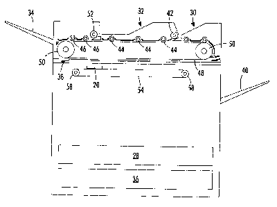
[0015] FIG. 2 is a cross section depicting an embodiment of the invention
comprising a multipurpose device which scans, images, and erases transient
documents such as a paper sheet coated with a photochromic alkoxy modified
dithienylethene. FIG. 3 is a plan view detailing a scan head and drive
assembly of
FIG. 2.
[0016]As depicted in FIGS. 2 and 3, the device can be designed so that the
transient document page is placed in a stationary position relative to a
moving scan
head, such as that found with a flatbed scanner device. In an alternate
embodiment,
the scan head can remain stationary while the transient document page is moved
past the scan head.
[0017]As depicted in FIGS. 2 and 3, a scan head 20 comprises a scanning
light source (scan bar) 22 which can comprise a wide spectrum lamp such as a
fluorescent or xenon lamp, or multiple color light emitting diode (LED)
emitter array
which provides sufficient illumination of a previously printed or imaged page
to allow
the device to copy the printed page to a blank transient document or to an
electronic
file. For example, the scanning light source can provide a visible light
wavelength in
the range of about 400 nm to about 700 nm at an intensity sufficient to
illuminate the
page for copying. The wavelength and intensity of the scanning light source
should
be sufficient to allow for scanning but not for imaging or erasing, and will
depend on
the photochromic coating used. In an embodiment using a wide spectrum lamp,
filters to remove UV and IR light, as well as other wavelengths which might
undesirably erase or write to the photochromic coating.
I
CA 02696069 2010-03-09
[0018]The ink, toner, or photochromic pattern can be electronically coded by
a scanner imager photodetector 24, such as a charge coupled device (CCD), CMOS
imager, or a contact image sensor (CIS). A CCD array, for example, collects
reflected photons from the image via mirrors (not individually depicted). In
the case
of the wide spectrum lamp, RGB filters can be employed, and photons can be
collected on the CCD in grayscale, then a color image is produced by analyzing
the
number of photons reflected (absorbed) when each filter is used for a specific
location on the page. From this information, an RGB colormap can be produced
to
result in a color image. In the case of an LED array outputting a number of
different
wavelengths, the spectrum will be narrow for each LED. To build a colormap
with an
LED array, one or more red LEDs are activated and the number of reflected
photons
received by the CCD array is analyzed to count the red depth (for example).
The
process is then repeated to determine the green depth and the blue depth. The
depth of each wavelength is analyzed to result in a color image. It is to be
understood that many variants are possible to produce a color, grayscale, or
black
and white image.
[0019]In a second embodiment, the device comprises an erasing light source
(erase bar) 26 such as a thermal (heat) source supplied by IR radiation, or a
visible
light source which is sufficient to erase a printed image from the transient
document.
An exemplary IR light source comprises a quartz bulb (quartz halogen heater)
which
outputs a wavelength of 1100 nm at an intensity and duration sufficient to
erase the
image from the photochromic coating. To expedite erasing of a transient
document,
more than one light source, such as activation of both an IR light source 24
and the
scanning light source 22, can be utilized. To further decrease the time to
erase the
document, the intensity of the scanning light source can be increased during
6
CA 02696069 2010-03-09
erasure, or both the IR source and a different light source optimized at a
wavelength
to minimize erasure time can be used. It may be desirable for the scanning
light
source to output a minimum intensity during a scan cycle to prevent fading of
a
transient document image, and to increase the intensity of the scan head
during an
erase cycle to expedite erasure of the image.
[0020]In a third embodiment, an imaging light source (imaging bar, not
individually depicted) such as a UV light source is provided, for example at a
wavelength of 5400 nm at an intensity and duration sufficient to produce an
image,
which will depend on the characteristics of the photochromic coating used. The
imaging light source can be passed through a light mask to pattern the light
source
to print a desired image on the transient document, or the light source can
comprise
a light pen such as that provided by a UV laser. In either case, the imaging
light
source is patterned and imaged directly on the transient document to print a
pattern
on the document. In one embodiment, the imaging light source is internal to
the
machine, for example internal to a print engine (not individually depicted)
and near
the feed tray(s) 28, 36, and not on the scan bar. Other configurations are
contemplated. Light shielding can be employed to ensure that stray light does
not
image transient documents near the UV light source.
[0021]The multipurpose device can also comprise a blank page storage area
28, which can be a blank page storage feed tray which stores blank (either
unimaged
or previously erased) sheets for subsequent use.
[0022]Further, the device can include an original (printed) page storage area
30 (i.e. a "to be copied" storage tray, for example) for storing one or more
pages
which are to be scanned and/or copied. Suitable documents to be scanned can
include an imaged transient document or a conventional page printed using ink
or
7
CA 02696069 2010-03-09
toner. Once a document is copied, it can be returned to the "to be copied"
storage
tray 30. If the document to be copied includes more than one page, each page
can
be copied and returned to this tray serially. In the alternative, the device
can also
include a separate tray such as a "copy complete" tray which receives pages
after
they have been copied.
[0023]The multipurpose device can also comprise a "to be erased" page
storage area 32, for example an erasure storage tray. The erasure storage tray
can
store one or more transient documents having an image which is to be erased. A
separate erasure tray with sufficient warning indicia may reduce accidental
erasure
of documents which are to be copied. The design could allow for erasure from
the "to
be erased" tray and not allow erasure from the "to be copied" tray. In the
alternative,
a single tray which functions as both the "to be copied" tray and the "to be
erased"
tray is also envisioned. Once the sheets have been erased, they can be
returned to
the "to be erased" storage area 32, returned to a separate erased sheet output
tray
34, or returned to a feed tray 36 for immediate reuse during subsequent
copying.
8
CA 02696069 2010-03-09
[0024]Additionally, the device can comprise an automatic document feeder
(ADF) which performs several document transportation functions. For example,
the
ADF can transfer a blank page from the blank page storage tray 28 to an
imaging
location (not individually depicted). At the imaging surface, the imaging
light source
such as a UV laser prints image on the blank page. Then, after imaging, the
ADF
transports the imaged transient document to a printed page storage area such
as a
printed page output tray 40.
[0025]Further, the ADF can transfer a printed page from the "to be copied"
storage tray 30 to the scanning surface 38. The scanning light source 22
illuminates
the printed page and the device scans and copies the image onto a blank
transient
document or to an electronic file for faxing or emailing. Thus an embodiment
of the
present invention also functions as an integrated fax machine. Additionally,
the ADF
can preferably transfer an imaged page from the erasure storage tray 32 to the
scanning surface 38 where it is illuminated by the erasing light source 26.
[0026]Transport of pages can be performed using a series of rollers. For
example, pickup roller 42 can select one sheet from the "to be copied" tray
30, and a
series of rollers 44, 46, in conjunction with a rotating drive belt 48 and
rollers 50,
transports the sheet to the scanning surface 38. Similarly, a sheet to be
erased is
selected by pickup roller 52, and rollers 46, in conjunction with the drive
belt 48 and
drive belt rollers 50, transports the sheet to the scanning surface 38. The
scan head
20 is moved using a drive assembly comprising a drive belt 54 connected to a
drive
motor (not depicted) along slide rails 56 using scan head drive belt rollers
58.
[0027]The multipurpose device can also include a control panel (not
individually depicted) comprising, for example, a touchpad or series of
buttons which
allows user control and a user-readable setup and status screen.
9
CA 02696069 2010-03-09
[0028] In use, the user can select one (or more) functions from a number of
different functions provided by the multipurpose device through the use of the
control
panel.
[0029] To scan a previously printed document such as an ink or toner
document or a transient document, for example, the user can place the document
to
be scanned in the "to be copied" storage tray 30 and select the copy function
via the
control panel. The ADF will transfer the document to be printed to the
scanning
surface 38 over the scan head 20, where the scanning source 22 illuminates the
document sufficiently for scanning. The illuminated, original image pattern is
scanned by the scanner imager 24 such as a CCD array and can be stored in
memory (not individually depicted) within the device.
[0030] If the copied document is to be printed as a transient document, after
scanning and storing the image, the document to be copied can be returned to
the
"to be copied tray" 30 and the print engine transports a blank page from the
blank
page feeder tray 28 to the imaging location, for example at a location
internal to the
device near the feeder tray(s). The original image pattern is retrieved from
memory
and imaged onto the transient document using the imaging light source. Imaging
can
be performed using a microprocessor for processing of the image and control of
the
imaging source, such as a UV laser, to print the image on the photochromic
coating
14 on the transient document sheet 10. Once printed, each transient document
page
is transported by the ADF to the printed page output tray 40.
[0031] In an alternative to printing a scanned document (or in addition to
printing the scanned document), the stored original image can be copied to a
file for
later use (faxing, emailing, printing) or can be immediately faxed, emailed,
etc. via
information supplied by the user through the control panel.
I
CA 02696069 2010-03-09
&
[0032] In another embodiment, the device scans the document to be copied
and begins printing the scanned image on the blank transient document prior to
completing the scan. Because, in this embodiment, the scanning source and the
imaging source are at different locations of the device, this assists in
minimizing the
time from initiating the scan to completing the copy.
[0033] To erase a transient document, a user can place the page(s) to be
erased in the erasure tray 32. After selecting the erase function from the
control
panel, the ADF selects each sheet in turn using pickup roller 54 and
transports each
page to be erased to the erase light source 26 where the document is
illuminated (for
example, using the IR light source 26 to heat the document and the scanning
light
source 22 to minimize erase time) to erase the document. The rate of movement
of
the scan head during erasure may be different than the rate of movement during
scanning to ensure complete erasure in a minimum time. The conditions
necessary
to effect complete erasure of the document may vary depending on the chemical
formulation used to coat the transient document. After erasing the document,
the
erased page can be transported by the ADF to the erased page tray 34, or
returned
to a separate blank page feed tray 36 or to feed tray 28 for immediate reuse.
[0034] If elevated temperature of the transient document is used as a
condition for erasure, it is contemplated that the region where the document
is
erased (for example, scanning surface 38) can be insulated to maximize thermal
efficiency and to minimize the time required to effect complete erasure of a
transient
document. Similarly, it is contemplated that the multipurpose device can
comprise a
cooling unit such that, during scanning of a transient document, the scanning
surface
is cooled such that any undesired erasure of the document is minimized. This
may
11
CA 02696069 2010-03-09
be particularly useful for a scanning cycle which immediately follows an
erasure
cycle.
[0035]Additionally, if the multipurpose device comprises a flatbed design such
as that depicted, the device can comprise a glass window for supporting the
page
during copying, writing, or erasing of an image. In another embodiment, a
quartz
window may have improved wavelength transmission properties over a glass
window. For example, a quartz window may heat faster and hold heat better than
a
glass window and thus minimize erasure time.
[0036]A temperature sensor can be used to ensure that thermal conditions
are sufficient to completely erase a transient document during an erase cycle.
The
temperature sensor can also be useful to ensure that the temperature in the
region
of the scan head is not elevated during a scan cycle, which could result in
undesired
erasure of a transient document being scanned.
[0037]An "archive" scan mode is also contemplated. In this mode, a user
places a previously imaged transient document into the "to be copied" tray 30,
and
selects the archive mode from the control panel. The previously imaged
transient
document is scanned, and the original image pattern is stored in memory and
written
to a file. After scanning, the image is erased from the transient document,
and the
page can be transported by the ADF to the erased page tray 34 or to the blank
page
feed tray 28 or 36 for reuse. A temperature sensor would be useful in this
mode,
particularly if document erasure is at least partially carried out by elevated
temperatures. The temperature sensor could be used to ensure that the
temperature
in the region of the scanning surface 38 has cooled sufficiently (or has been
caused
to cool through the use of a cooling element) after an erasure prior to
transporting
12
CA 02696069 2010-03-09
another transient document page to the scan head to prevent fading of the
transient
document image prior to scanning.
[00381Thus various embodiments of the invention provide a method and
device which is cost effective and allows for efficient handling and erasure
of
transient documents. In one embodiment, the image scanning device comprises a
scan bar and an IR source, such as a quartz bulb, co-located on a scan bar to
heat
the chemical imaging formulation which coats the page and allows for a
printable
and erasable image pattern. Heating the page with the IR source effects or
expedites
erasure of an image from the coating. Additionally, the IR source can be
enabled
simultaneously with the scanning light source to more quickly erase the page,
or with
another light source having a wavelength optimized for erasure. A multipurpose
device comprising the invention can comprise various elements, such as: a
separate
tray/divider for storing transient documents which are no longer needed (ready
to be
erased); a separate tray/divider for holding sheets that have been erased and
are
ready to be used again; a separate erase mode that turns on the heater and
scans at
the necessary rate to erase a document; a user interface to initiate an erase
sequence, and; insulation of the ADF to minimize energy loss if the heating
cycle is
long.
[0039]The embodiments of the present teachings conveniently manage
transient documents to expose them to the necessary wavelengths of light to
scan,
print, and erase a transient document. The multipurpose device can be
controlled by
a microprocessor contained within the device, or it can be controlled by a
separate
computer or microprocessor which is part of a larger network of devices, such
as a
plurality of office devices, printing devices, etc.
13
I
CA 02696069 2010-03-09
=
[0040] Notwithstanding that the numerical ranges and parameters setting
forth the broad scope of the invention are approximations, the numerical
values set
forth in the specific examples are reported as precisely as possible. Any
numerical
value, however, inherently contains certain errors necessarily resulting from
the
standard deviation found in their respective testing measurements. Moreover,
all
ranges disclosed herein are to be understood to encompass any and all sub-
ranges
subsumed therein. For example, a range of "less than 10" can include any and
all
sub-ranges between (and including) the minimum value of zero and the maximum
value of 10, that is, any and all sub-ranges having a minimum value of equal
to or
greater than zero and a maximum value of equal to or less than 10, e.g., 1 to
5. In
certain cases, the numerical values as stated for the parameter can take on
negative
values. In this case, the example value of range stated as "less that 10" can
assume
negative values, e.g. ¨ 1, -2, -3, -10, -20, -30, etc.
14
I
CA 02696069 2010-03-09
,
[0041]While the invention has been illustrated with respect to one or more
implementations, alterations and/or modifications can be made to the
illustrated
examples without departing from the spirit and scope of the appended claims.
In
addition, while a particular feature of the invention may have been disclosed
with
respect to only one of several implementations, such feature may be combined
with
one or more other features of the other implementations as may be desired and
advantageous for any given or particular function. Furthermore, to the extent
that
the terms "including," "includes," "having," "has," "with," or variants
thereof are used
in either the detailed description and the claims, such terms are intended to
be
inclusive in a manner similar to the term "comprising." The term "at least one
of" is
used to mean one or more of the listed items can be selected. Further, in the
discussion and claims herein, the term "on" used with respect to two
materials, one
"on" the other, means at least some contact between the materials, while
"over"
means the materials are in proximity, but possibly with one or more additional
intervening materials such that contact is possible but not required. Neither
"on" nor
"over" implies any directionality as used herein. The term "conformal"
describes a
coating material in which angles of the underlying material are preserved by
the
conformal material. The term "about" indicates that the value listed may be
somewhat altered, as long as the alteration does not result in nonconformance
of the
process or structure to the illustrated embodiment. Finally, "exemplary"
indicates the
description is used as an example, rather than implying that it is an ideal.
Other
embodiments of the invention will be apparent to those skilled in the art from
consideration of the specification and practice of the invention disclosed
herein. It is
intended that the specification and examples be considered as exemplary only,
with
a true scope and spirit of the invention being indicated by the following
claims.