Note: Descriptions are shown in the official language in which they were submitted.
CA 02696489 2010-03-11
SURGICAL ACCESS ASSEMBLY INCLUDING SHIELD MEMBER
BACKGROUND
1. Technical Field
[00021 The present disclosure relates to a surgical access assembly that is
adapted for removable
insertion into a patient's tissue. More specifically, the present disclosure
relates to a surgical
access assembly including a shield member that is configured, dimensioned, and
adapted to
inhibit contact between a practitioner and any fluid escaping from a surgical
worksite during,
e.g., laparoscopic or endoscopic procedures.
2. Background of the Related Art
[0003] In contemporary medical practice, many surgical procedures are
performed through
access asemblies, e.g., trocar and cannula assemblies. 'These devices
incorporate narrow tubes or
cannulae percutaneously inserted into a patient's body, through which one or
more surgical
instruments may be introduced to access a surgical worksite. Generally, such
procedures are
referred to as "endoscopic", and if performed in the patient's abdomen, in
which case the
procedure is referred to as "laparoscopic," or an arthroscopic procedure where
surgery is
CA 02696489 2010-03-11
performed on a joint ligament or the like - all procedures being characterized
as minimally
invasive.
[0004] In minimally invasive procedures, a fluid, such as an insufflation gas,
is often
communicated into the surgical worksite prior to the introduction of any
surgical instrumentation
to the patient's body. Introducing such fluids increases the pressure within
the internal worksite,
which thereby separates the patient's internal organs from the overlying
tissue, e.g., the patient's
skin, to increase visibility and/or create a larger, more accessible space in
which to work. This
increase in internal pressure also tends to result in the expulsion of fluids,
including the
insufflation gas, from the surgical worksite. In arthroscopic procedures, an
inrigant such as a
saline may be introduced to clean debris, bone chips etc, and/or provide
greater access to the
underlying bone or tissue area. The irrigant solution is also subject to
emission toward the
surgeon
[0005] Given the desirability of maintaining the integrity of the expanded
surgical worksite,
surgical access assemblies typically incorporate one or more seals through
which the surgical
instruments are inserted in an attempt to establish a substantially fluid-
tight seal in both the
presence and absence of surgical instrumentation, and curtail the escape of
fluid. However, in
the event that fluid does escape, either through or around the surgical access
assembly, known
surgical access assemblies are generally devoid of any mechanism that will
deflect or redirect
such fluid to inhibit contact with the practitioner.
SUMMARY
[00061 In one aspect of the present disclosure, a surgical access assembly is
disclosed that
includes a housing, an access member, a seal member positioned within the
housing that is
2
CA 02696489 2010-03-11
adapted to removably receive a surgical instrument such that a substantially
fluid-tight seal is
formed therewith, and a shield member.
[0007] The access member extends distally from the housing, and includes a
proximal end, a
distal end, and a longitudinal opening for the reception of the surgical
instrument
[0008] The shield member is at least partially positioned externally of the
housing, e.g.
proximally thereof, to deflect fluid communicated from the housing. The shield
member
includes a rim and an opening extending through the shield member that is
configured and
dimensioned to receive the surgical instrument.
10009] The shield member may assume a variety of configurations without
departing from the
scope of the present disclosure, such as a substantially planar or arcuate
configuration. In those
embodiments where the shield member exhibits an arcuate configuration, the
shield member may
be curved in a distal direction such that an outer edge of the shield member
is positioned distally
of the opening extending through the shield member.
[0010] The shield member may be configured and dimensioned to frictionally
engage an outer
surface of the surgical instrument. Additionally, or alternatively, the shield
member may include
an o-ring positioned within the opening extending through the shield member
that is at least
partially formed from a substantially resilient material.
[0011] The shield member is repositionable between a first position, in which
the opening
defines a first transverse dimension that is smaller than an outer transverse
dimension of the
surgical instrument, and a second position, in which the opening defines a
second transverse
3
CA 02696489 2010-03-11
dimension that substantially approximates the outer transverse dimension of
the surgical
instrument.
[0012] In one embodiment, the shield member is at least partially formed of a
substantially
resilient material such that the shield member is normally biased towards the
first position. In
this embodiment, the shield member is repositioned from the first position to
the second position
upon insertion of the surgical instrument through the opening extending
through the shield
member.
[00131 In another embodiment, the shield member may be adapted for manual
repositioning
between the first position and the second position. For example, the shield
member may include
a collet mechanism that is at least partially positioned within the opening
extending through the
shield member, and movable between an expanded configuration, corresponding to
the first
position of the shield member, and a restricted configuration, corresponding
to the second
position of the shield member. In this embodiment, when the collet mechanism
is in the
expanded configuration, the surgical instrument is insertable through the
collet mechanisms, and
when the collet mechanism is in the restricted configuration, the collect
mechanism engages an
outer surface of the surgical instrument to maintain the position of the
surgical instrument
relative to the shield member.
[0014] In another embodiment, the shield member may include a clamp mechanism
that is at
least partially positioned within the opening extending through the shield
member, and movable
between an open configuration, corresponding to the first position of the
shield member, and a
closed configuration, corresponding to the second position of the shield
member. To facilitate
movement of the clamp mechanism between the open configuration and the closed
4
CA 02696489 2010-03-11
configuration, it is envisioned that the clamp mechanism may include a lever
configured for
manual manipulation.
[00151 In another aspect of the present disclosure, a surgical access assembly
is disclosed that
includes a housing, an access member extending distally from the housing with
proximal and
distal ends that is configured to removably receive a surgical instrument, and
a shield member.
The shield member is at least partially positionable proximally of the housing
and about the
surgical instrument to substantially intenupt the communication of fluid from
the housing in a
proximal direction.
[0016) In yet another aspect of the present disclosure, a method of assembling
a surgical access
assembly is disclosed that includes the steps of (i) providing a housing and
an access member
extending distally from the housing, wherein the access member includes a
longitudinal opening
for reception of a surgical instrument; (ii) providing a shield member
including an opening
extending theretlu-ough that is configured and dimensioned to receive the
surgical instrument;
(iii) positioning the surgical instrument within the opening extending through
the shield member;
and (iv) positioning the surgical instrument within the elongate access
assembly such that the
shield member is at least partially positioned proximally of the housing to
interrupt the
communication of fluid from the housing in a proximal direction.
[00171 These and other features of the surgical access assembly and shield
member disclosed
herein will become more readily apparent to those skilled in the art through
reference to the
following detailed description of various embodiments of the present
disclosure.
CA 02696489 2010-03-11
BRIEF DESCRIPTION OF THE DRAWINGS
[0018] FIG. 1 is a side, schematic view of a surgical access assembly
including one embodiment
of a shield member in accordance with the present disclosure;
[0019] FIG. 2 is a cross-sectional view of the shield member seen in FIG. 1;
[0020] FIG. 3 is a top, perspective view of the shield member seen in FIG. 1;
[0021] FIG. 4 is a cross-sectional view of an alternate embodiment of the
shield member seen in
FIG. 1 including a tapered opening extending therethrough;
[0022] FIG. 5A is a top, perspective view of an alternative embodiment of the
shield member
seen in FIG. 1 including an elliptical opening extending therethrough;
[00231 FIGS. 5B and 5C are top, perspective views of an alternative
embodiments of the shield
member seen in FIG. 1 including linear openings extending therethrough;
[0024] FIG. 6A is a cross-sectional view of an alternate embodiment of the
shield member seen
in FIG. 1 including a rim that is positioned proximally of the opening
extending through the seal
member;
[00251 FIG. 6B is a top, perspective view of an alternative embodiment of the
shield member
seen in FIG. 1 including a substantially planar configuration;
[0026] FIG. 7A is a cross-sectional view of the shield member seen in FIG. 1
shown in a first
position prior to the insertion of a surgical instrument;
6
CA 02696489 2010-03-11
[0027] FIG. 7B is a cross-sectional view of the shield member seen in FIG. 1
shown in a second
position following insertion of a surgical instilment;
[0028] FIG. 8 is a cross-sectional view of an alternative embodiment of the
shield member seen
in FIG. 1 including an o-ring positioned within the opening extending through
the shield
member;
[0029] FIG. 9 is a top, perspective view of the embodiment of the shield
member shown in FIG.
8;
[0030] FIG. IOA is a top, perspective view of the another embodiment of the
shield member
shown in FIG. 1 including a collect mechanism at least partially positioned
within the opening
extending through the shield member, wherein the collet mechanism is
illustrated in an expanded
configuration with a surgical instrument inserted therethrough;
[0031] FIG. 10B is a top, perspective view of the embodiment of the shield
member shown in
FIG. 10A showing the collet mechanism in a restricted configuration with the
surgical
instrument inserted therethrough;
[0032] FIG. 11 is a top, perspective view of the another embodiment of the
shield member
shown in FIG. 1 including a clamp mechanism at least partially positioned
within the opening
extending through the shield member, wherein the clamp mechanism is
illustrated with a surgical
instrument inserted therethrough;
[0033] FIG. 12A is a top, perspective view of the embodiment of the shield
member shown in
FIG. 11 illustrating the clamp mechanism in an open configuration; and
7
CA 02696489 2010-03-11
[0034] FIG. 12B is a top, perspective view of the embodiment of the shield
member shown in
FIG. 11 illustrating the clamp mechanism in a closed configuration.
DETAILED DESCRIPTION
[0035] In the drawings, and in the following description, wherein like
references characters
identify similar or identical elements, the tern "proximal" should be
understood as referring to
the end of the disclosed surgical access assembly, or any component thereof,
that is closest to the
practitioner during proper use, while the term "'distal" should be understood
as referring to the
end that is furthest from the practitioner. Additionally, the term "surgical
instrument" should be
understood to include any surgical instrument that may be employed during the
course of
surgical procedure, including but not limited to an obturator, a surgical
stapling device, or the
like, and the term "fluid" should be understood as referring to any fluid that
may be present at a
surgical worksite, such as insufflation gases, saline, (e.g., in an
arthroscopic surgical procedure)
or bodily fluids.
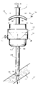
[00361 FIG. 1 illustrates a surgical access assembly 1000 including a housing
1002, an elongate
access member 1004, and a shield member 1006. The housing 1002 defines an
internal cavity
1008 that is configured and dimensioned to accommodate a seal assembly 1010,
and may be any
structure suitable for this intended purpose. The seal assembly 1010 is
adapted to removably
receive a surgical instrument "I" such that a substantially fluid-tight seal
is formed therewith.
Illustrative examples of suitable seal assemblies are discussed in U.S. Patent
No. 6,702,787 to
Racenet the entire contents of which are incorporated by reference herein]. As
depicted in FIG.
1, the housing 1002 includes a port 1012 to permit the introduction of an
insufflation gas into an
internal surgical worksite "W" located beneath a patient's tissue "T."
8
CA 02696489 2010-03-11
[00371 The access member 1004 extends distally from the housing 1002 and is
dimensioned for
positioning within a percutaneous access point "P" formed in the patient's
tissue "T." The
access member 1004 includes respective proximal and distal ends 1014, 1016,
and defines a
longitudinal opening 1018. The longitudinal opening 1018 extends between the
respective
proximal and distal ends 1014, 1016 of the access member 1004 along a
longitudinal axis "A,"
and is configured and dimensioned for the internal receipt of the surgical
instrument "I." The
access member 1004 defines an opening 1020 at the distal end 10I6 thereof to
allow the surgical
instrument "I" to pass into the surgical worksite "W."
[00381 Referring now to FIGS. 2 and 3 as well, the shield member 1006 will be
discussed. The
shield member 1006 defines an overall transverse dimension "Ds," and includes
a proximal
surface 1022, a distal surface 1024, an opening 1026, and an outer edge or rim
1028. Although
the transverse dimension "Ds" of the shield member 1006 is illustrated as
approximately
equivalent to an outer dimension "DH" of the housing 1002 (FIG. 1) of the
surgical access
assembly 1000, it shall be appreciated that the transverse dimension "Ds" of
the shield member
1006 can be substantially larger or smaller dependent upon the particular
circumstances of the
surgical procedure in which the shield member 1006 is employed.
[0039] The opening 1026 extends between the respective proximal and distal
surfaces 1022,
1024, and thus through the shield member 1006, to accommodate the insertion
and removal of
the surgical instrument "I" (FIG. 1). While the opening 1026 is illustrated as
extending
uniformly through the shield member 1006 in FIGS. 1-3, alternate
configurations for the
opening 1026 are also contemplated. For example, as seen in FIG. 4, the
opening 1026 may be
tapered to define a first aperture 1030A on one surface of the shield member
1006, e.g., the
proximal surface 1022, and a second aperture 10308 on the other surface, e.g.,
the distal surface
9
CA 02696489 2010-03-11
1024, wherein the first aperture 10308 and the second aperture 1030B define
differing transverse
dimensions. Also, while the opening 1026 is depicted as substantially annular
in FIGS. 1-3, it is
envisioned that the opening 1026 may define any suitable geometric
configuration, e.g., elliptical
(FIG. 5A) or linear (FIGS. 5B, SC).
[0040] Referring again to FIGS. 1-3, the rim 1028 of the shield member 1006
may be formed of
the same material as the shield member 1006, or alternatively, may include a
different material.
It is further contemplated that the material comprising the rim 1028 may be
substantially rigid or
substantially non-rigid in nature.
[0041] As shown in FIG. 1, the shield member 1006 is separated from, and
positioned externally
of the housing 1002. However, in alternative embodiments of the surgical
access assembly
1000, it is contemplated that a portion of the shield member 1006 may be
attached to, or
positioned within, the housing 1002. Additionally, although the shield member
1006 is
illustrated as defining an arcuate configuration in which the rim 1028 of the
shield member is
positioned distally of the opening 1026 extending therethrough (FIGS. 1-3),
other configurations
are not beyond the scope of the present disclosure. For example, the rim 1028
of the shield
member may be positioned proximally of the opening 1026 extending
therethrough, as seen in
FIG. 6A, or the shield member 1006 may define a substantially planar
configuration, as seen in
FIG. 6B.
[00421 The shield member 1006 may be formed fromL any suitable material,
including but not
being limited to elastomeric materials such as natural rubber, synthetic
polyisoprene, butyl
rubber, halogenated butyl rubbers, polybutadiene, styrene-butadiene rubber,
nitrile rubber,
hydrogenated nitrite rubbers, chloroprene rubber, ethylene propylene rubber,
ethylene propylene
CA 02696489 2010-03-11
diene rubber, epichlorohydrin rubber, polyacrylic rubber, silicone rubber,
fluorsilicone rubber,
fluoroelastomers, perfluoroelastomers, polyether block amides,
chlorosulfonated polyethylene,
ethylene-vinyl acetate, thermoplastic elastomers, thermoplastic vulcanizers,
thermoplastic
polyurethane, thermoplastic olefins, resilin, elastin, and polysulfide rubber.
Forming the shield
member 1006 from such a material permits the shield member 1006 to resiliently
accommodate
the insertion, manipulation, and removal of the surgical instruments "I" that
may vary in size,
e.g., in their outer dimension "DL" (FIG. 1). Specifically, upon insertion of
the surgical
instrument "I", the shield member 1006 is moved from a first position (FIG.
7A), in which the
opening 1026 extending through the shield member 1006 defines a first, or
initial transverse
dimension "Di" that is smaller than the outer dimension "Di" of the surgical
instrument "l," to a
second position (FIG. 7B), in which the opening 1026 defines a second,
enlarged transverse
dimension "D2."
[0043] The resilient material comprising the shield member 1006 attributes a
normal bias toward
the first such that the shield member 1006 to return to the first position
following removal of the
surgical instrument "I" from the opening 1026. Additionally, the normal bias
of the shield
member 1006 allows the opening 1026 to realize a second transverse dimension
"D2" that
substantially approximates the outer dimension "Dr" of the surgical instrument
"I" (FIG. 7B)
such that the shield member 1006 frictionally engages an outer surface 1032 of
the surgical
instrument "I" at the opening 1026 extending through the shield member 1006.
This frictional
engagement allows the shield member 1006 to be reliably positioned at any
location along the
portion of the surgical instrument "I" extending proximally of the housing
1002. Additionally,
the frictional engagement between the shield member 1006 and the surgical
instrument "I"
allows the practitioner to reliably reposition the shield member 1006 if
necessary. It is
11
CA 02696489 2010-03-11
envisioned herein that the normal bias of the shield member 1006 towards the
first position may
be considerable enough to establish a substantially fluid-tight seal between
the shield member
1006 and the outer surface 1032 of the surgical instrument "I".
[0044] Referring now to FIGS. 1-3, 7A, and 7B, the use and function of the
surgical access
assembly 1000 (FIG. 1) during the course of a minimally invasive surgical
procedure will be
discussed. Initially, i.e., prior to beginning the procedure, the surgical
instrument "I" is inserted
through the opening 1026 in the shield member 1006 such that the shield member
will be
positioned proximally of the housing 1002 upon insertion of the surgical
instrument "I" into the
surgical access assembly 1000. Thereafter, the practitioner orients the
surgical access assembly
1000 such that the distal end 1014 of the access member 1004 is positioned
beneath the patient's
tissue "'T" within the surgical worksite "W" such as a joint or ligament in
all arthroscoplc
procedure, or an insufflated body cavity. Fluid, such as an irrigant in the
arthroscopic procedure
or insufflation gas, can be introduced into the surgical worksite "W" through
the port 1012 to
increase visibility and/or create a larger, more accessible space in which to
work or clear bone
chips or debris in the joint area.
10045] Following placement of the surgical access assembly 1000 as described
above, fluid
escaping from the surgical worksite "W" during the course of the surgical
procedure, either
around the surgical access assembly 1000 or therethrough, will be generally
prevented from
reaching the practitioner by the shield member 1006, thereby protecting the
practitioner from
potential exposure to objectionable substances. Following placement of the
surgical access
assembly 1000, the practitioner can insert the surgical instrument "I" into
the surgical worksite
"W" through the surgical access assembly 1000 to carry out the remainder of
the procedure.
12
CA 02696489 2010-03-11
[0046] Referring now to FIGS. 8-12B, alternative embodiments of the shield
member 1006
(FIGS. 1-3) will be discussed. Each embodiment of the shield member shown in
FIGS. 8-12B
is substantially similar to the shield member 1006 discussed above with
respect to FIGS. 1-3,
and accordingly, will only be discussed with respect to their differences
therefrom.
[0047] With particular reference to FIGS. 8 and 9, a shield member 2006 is
disclosed that
includes an o-ring 2034 positioned within the opening 2020 extending through
the shield
member 2006. Upon insertion of the surgical instrument "I" (FIG. 1), the o-
ring 2034 facilitates
engagement with the outer surface 1032 thereof such that a substantially fluid-
tight seal is
formed between the surgical instrument "I" and the shield member 2006. The o-
ring 2034 can
be formed from any material suitable for the intended purpose of establishing
such a seal,
including but not limited to rubber or polymeric materials.
[0048] FIGS. 10A and 10B illustrate a shield member 3006 that includes a
collet mechanism
3036 positioned at least partially within the opening 3020. The collet
mechanism 3036 allows
for selective, manual repositioning of the shield member 3006 between the
first position (FIG.
7A) and the second position (FIG. 7B), and consequently, adjustment of the
effective inner
transverse dimension "DT" of the opening 3020. Specifically, the collet
mechanism 3036 is
movable from an expanded configuration (FIG. l0A), corresponding to the first
position of the
shield member 3006, and a restricted configuration (FIG. lOB), corresponding
to the first
position of the shield member 3006.
[0049] When the collet mechanism 3036 is in the expanded configuration, the
effective inner
transverse dimension "DT" of the opening 3020 is large enough to allow for
insertion of the
surgical instrument "I" (FIG. 1) therethrough. However, when the collet
mechanism is moved to
13
CA 02696489 2010-03-11
the restricted configuration, the effective inner transverse dimension "D-r"
of the opening 3020 is
reduced to substantially approximate the outer dimension "Dr" of the surgical
instrument "I"
such that the collet mechanism 3036 engages the outer surface 1032 of the
surgical instrument
"I" to substantially maintain the position thereof relative to the shield
member 3006.
[0050] With reference now to FIGS. 11-12B, a shield member 4006 is illustrated
that includes a
clamp mechanism 4038 allowing for selective, manual repositioning of the
shield member 4006
between the first position (FIG. 7A) and the second position (FIG. 7B), and
consequently,
adjustment of the effective inner transverse dimension "Dr" of the opening
4020. Specifically,
the clamp mechanism 4038 is movable between an open configuration (FIG. 12A),
corresponding to the first position of the shield member 4006, and a closed
configuration (FIG.
12B), corresponding to the first position of the shield member 4006.
[0051] The clamp mechanism 4038 includes a collar 4040 positioned at least
partially within the
opening 4020 extending through the shield member 4006. The collar 4040 defines
a split 4042
(FIG. 11) which allows the collar 4040 to be flexible and compressible against
the outer surface
1032 of the surgical instrument "I." First and second mounting projections,
referred to
respectively by reference characters 4044, 4046 are formed on either side of
the split 4042. The
clamp mechanism 4038 further includes a lever 4048 and a cam bar 4050. A first
end 4052 of
the lever 4048 is pivotally connected to the first mounting projection 4044 by
a first pin 4054,
and a first end 4056 of the cam bar 4050 is pivotally connected to the second
mounting
projection 4046 by a second pin 4058. A second end 4060 of the cam bar 4050 is
also pivotally
connected to a central portion 4062 of the lever 4048 by a third pin 4064.
14
CA 02696489 2010-03-11
[0052] The operation of the clamp mechanism will now be discussed with
continuing reference
to FIGS. 11-12B. Referring initially to FIGS. 11 and 12A, when the lever 4048
is in a generally
clockwise most position, the clamp mechanism 4038 is in the open configuration
(FIG. 12A),
wherein the distance between the mounting projections 4044, 4046 is at a
maximum, and the
effective inner transverse dimension "DT" of the opening 4020 (FIGS. 12A,
12B), which is
defined by the collar 4040, is large enough to allow for insertion of the
surgical instrument "I"
(FIG. 11) through the opening 4020. As the lever 4048 is rotated
counterclockwise, the second
end 4060 of the cam bar 4050 moves through an are, and drives the second
mounting projection
4046 towards the first mounting projection 4044, thereby moving the clamping
mechanists 4038
into the restricted configuration (FIG. 12B). In the restricted configuration,
the effective inner
transverse dimension "DT" of the opening 4020 is reduced to substantially
approximate the outer
dimension "Di" of the surgical instrument "I" such that the clamp mechanism
4038, specifically
the collar 4040, engages the outer surface 1032 (FIG. 11) of the surgical
instrument "I" to
substantially maintain the position thereof relative to the shield member
4006.
[0053] When the third pin 4064 is in level alignment along line B-B with the
first pin 4054 and
the second pin 4058 (FIG. 11), the mounting projections 4044, 4046 are at
their closest distance,
and exert a maximum force against the outer surface 1032 of the surgical
instrument "I." As the
second end 4060 of the cam bar 4050 moves below line B-B, the distance between
the mounting
projections 4044, 4046 is increased, thereby increasing the force that must be
applied to the lever
4048 to release the collar 4040 from the outer surface 1032 of the surgical
instrument "I," and
ensuring against inadvertent release of the clamp mechanism 4038.
[0054] The above description, disclosure, and figures should not be construed
as limiting, but
merely as exemplary of particular embodiments. It is to be understood,
therefore, that the
CA 02696489 2010-03-11
disclosure is not limited to the precise embodiments described, and that
various other changes
and modifications may be effected therein by one skilled in the art without
departing from the
scope or spirit of the disclosure. Additionally, persons skilled in the art
will appreciate that the
features illustrated or described in connection with one embodiment may be
combined with those
of another, and that such modifications and variations are also intended to be
included within the
scope of the present disclosure.
16