Note: Descriptions are shown in the official language in which they were submitted.
CA 02696990 2010-02-19
WO 2009/023972
PCT/CA2008/001525
1
TITLE OF THE INVENTION
ACETABULAR REAMER WITH LOCKING COLLAR
FIELD OF THE INVENTION
[0001] The present invention relates to the art of surgical devices. More
specifically, the present invention is concerned with an acetabular reamer.
BACKGROUND
[0002] Acetabular reamers are used in hip replacement surgery to prepare the
acetabulum of the hip of a patient before the attachment of an acetabular cup
thereto. In such surgeries, there is typically a need to prepare the
acetabulum so
that a substantially spherical cap-shaped surface is provided to receive a
substantially hemispherical acetabular cup. To that effect, a surgeon
typically
uses a reamer including a substantially hemispherical reaming element in which
asperities are formed. The reaming element is longitudinally mounted to the
distal
end of an axle and the axle is attached to a rotary power tool such as, for
example,
a drill. The drill rotates the axle about the longitudinal axis of the axle,
thereby
rotating the reaming element to allow reaming of the acetabulum.
[0003] Hip replacement surgery is performed typically after having performed a
relatively small incision in a patient, the incision being used for
introducing and
removing surgical instruments and tissue debris therethrough. Each time an
instrument is inserted in the patient, or removed therefrom, there is a risk
that soft
tissues adjacent the incision become damaged by this action.
[0004] In the above-described reaming method, the surgeon typically needs to
CA 02696990 2010-02-19
WO 2009/023972
PCT/CA2008/001525
2
remove and re-insert repeatedly the acetabular reamer to change the reaming
element by a reaming element having a slightly larger diameter in each
successive
iteration. This allows the surgeon to gradually ream the acetabulum to a
desired
shape and dimension.
[0005] In turn, this requires that many reaming elements be brought into an
operating room, which results in relatively large sterilizing costs.
Furthermore, the
repetitive insertion and removal of the acetabular reamer from the patient is
time-
consuming and may cause injuries to soft tissues adjacent the incision.
[0006] Another problem of many conventional acetabular reamers is that the
reaming element typically includes asperities that are spaced apart from each
other. These asperities therefore do not produce directly a relatively smooth
surface and the surgeon needs to move the acetabular reamer in a substantially
ball-joint-like motion inside the patient to achieve a substantially uniform
surface
suitable for the attachment of the acetabular cup thereto. Since the surgeon
typically does not see the result of this operation, there is always a risk
that the
resulting surface is not smooth enough and results in sub-optimal
implementation
of the acetabular cup. Another disadvantage of this motion is that, once
again, it
creates a risk of injuring soft tissues inside the patient.
[0007] A few acetabular reamers having variable dimensions have been
previously described. For example, U.S. patent 6,918,914 issued on July 19,
2005
to Bauer describes an acetabular reamer including arcuately-shaped segments
that are extendable and retractable about a center point to create variably
dimensioned recesses in an acetabular region. However, in this acetabular
reamer, when the arcuately-shaped segments are moved away from the central
CA 02696990 2013-08-01
3
location, the arcuately-shaped segments become spaced apart from each other,
which therefore create gaps therebetween. In turn, this requires that the
surgeon
operate the acetabular reamer substantially in the ball-joint-like motion
described
hereinabove. Also, when the acetabular reamer is used to ream the acetabulum,
mechanical forces transmitted by the arcuately-shaped segments to the
remainder
of the acetabular reamer are relatively large, which therefore requires that
the
mechanism used to extend and retract the arcuately-shaped segments be
relatively sturdy. This leads to a restriction to a relatively small number of
the
number of arcuately-shaped segments that can be provided because of size
limitations present in such reamers. Also, the surface formed by the arcuately-
shaped segments is spherical at only one single overall diameter. For other
dimensions, the reamed surface will deviate from a perfect sphere, and since
the
number of segments is relatively small, such deviations are relatively large
in the
acetabular reamer proposed by Bauer.
[0008] A US Patent Application filed by Termanini and published under the
publication number 2006/0217730 on September 28, 2006 describes another
acetabular reamer including deployable segments deployable by a deployment
mechanism. A disadvantage of this acetabular reamer resides in the presence of
pivots in the deployment mechanism, the pivots being load-bearing when the
acetabular reamer is in use. Such pivots are relatively fragile and introduce
failure
points in the design of this acetabular reamer. Also, manufacturing
imprecisions in
the pivots can lead to the creation of vibrations when the acetabular reamer
is in
use. Furthermore, the pivots form a structure that is relatively difficult to
clean and
sterilize.
[0009] Another extendable acetabular reaming system has been described by
Temeles in U.S. Patent 6,283,971 issued September 4, 2001. In this reamer, a
CA 02696990 2010-02-19
WO 2009/023972
PCT/CA2008/001525
4
reamer head has a convex forward surface attached to a plate that defines an
interior space therebetween. The forward space includes apertures extending
therethrough and the base plate includes a central aperture over which a
flexible
bladder is mounted within the interior space. The reaming system includes
cutting
blades mounted to the bladder and positioned so as to correspond with
respective
apertures. The bladder is inflatable so as to extend the blades through the
apertures to a variable extent. Once again, in this system, there are gaps
between
the blades, which will therefore not alleviate one of the problems mentioned
hereinabove. Also, any gap between the blades and the apertures will create
vibration in the acetabular reamer when the acetabular reamer is used to ream
the
acetabulum.
[0010] Accordingly, there is a need in the industry to provide an improved
acetabular reamer. An object of the present invention is therefore to provide
such
an acetabular reamer.
SUMMARY OF THE INVENTION
[0011] In a broad aspect, the invention provides an acetabular reamer for
reaming
an acetabulum, reaction forces being exerted onto the acetabular reamer by the
acetabulum when the acetabulum is reamed, the acetabular reamer comprising: a
body, the body defining a rotation axis about which the acetabular reamer is
rotatable; a reaming element operatively coupled to the body so as to be
movable
between a reaming element inner position and a reaming element outer position
relatively thereto, the reaming element being positioned further away from the
rotation axis in the reaming element outer position than in the reaming
element
inner position; an actuator operatively coupled to the reaming element for
moving
the reaming element between the reaming element inner and outer positions; and
CA 02696990 2010-02-19
WO 2009/023972
PCT/CA2008/001525
a reaming element lock configurable between a locked configuration and an
unlocked configuration, the reaming element lock being operatively coupled to
the
reaming element in a manner such that when the reaming element lock is in the
unlocked configuration, the reaming element is substantially freely movable by
the
actuator between the reaming element inner and outer positions, and when the
reaming element lock is in the locked configuration, the reaming element lock
substantially prevents the reaming element from moving relatively to the body;
the
reaming element lock being configured, sized and operatively coupled to the
reaming element and the body in a manner such that when the reaming element
lock is in the locked configuration and the reaction forces are exerted onto
the
reaming element, a larger portion of the reaction forces is transmitted to the
body
than to the actuator.
[0012] Advantageously, in some embodiments of the invention, the proposed
acetabular reamer includes a relatively large number of reaming elements as
the
actuator may have a relatively complex configuration while fitting within the
relatively small inner space defined by the reaming elements. Indeed, the
relatively large reaction forces exerted onto the acetabular reamer when in
use are
transmitted to the body not through the actuator, but through the reaming
element
lock. Since the reaming element lock may be configured so as to be relatively
sturdy while remaining confined within the surface defined by the reaming
elements, the proposed acetabular reamer is relatively sturdy even when
including
a relatively large number of reaming elements and a relatively fragile
actuator.
[0013] Furthermore, in some embodiments of the invention, the reaming elements
each define a respective reaming surface, the reaming surfaces being arranged
along the meridians of a substantially spherical-cap-shaped surface.
CA 02696990 2010-02-19
WO 2009/023972
PCT/CA2008/001525
6
[0014] Advantageously, in some embodiments of the invention, the reaming
surfaces are arranged such that there is a circumferential overlap between the
reaming surfaces of the reaming elements extending along each meridian, which,
therefore, eliminates gaps through which no reaming occurs when the acetabular
reamer is rotated about the rotation axis.
[0015] The proposed acetabular reamer is further ergonomic to use and
relatively
easily manufacturable using known materials and techniques.
[0016] The use of the proposed acetabular reamer allows an intended user to
use
only a relatively small number of components to ream cavities having various
dimensions.
[0017] In some embodiments of the invention, the proposed acetabular reamer is
relatively easily dismantled into individual components that are each
relatively
easily cleanable and sterilizable.
[0018] Another advantage of having an acetabular reamer including many
reaming elements resides in that the use of many reaming elements allows for
reaming a cavity that deviates only slightly from the surface of a perfect
sphere.
[00010] Other objects, advantages and features of the present invention will
become more apparent upon reading of the following non-restrictive description
of
preferred embodiments thereof, given by way of example only and in relation
with
the following Figures.
CA 02696990 2010-02-19
WO 2009/023972
PCT/CA2008/001525
7
BRIEF DESCRIPTION OF THE DRAWINGS
[0019] Figure 1, in a perspective view, illustrates an acetabular reamer in
accordance with an embodiment of the present invention;
[0020] Figure 2, in a side elevation view, illustrates the acetabular reamer
shown
in Fig. 1;
[0021] Figure 3, in a side cross-sectional view along the line A-A shown in
Fig. 2,
illustrates the acetabular reamer shown in Figs. 1 and 2;
[0022] Figure 4a, in a perspective view with parts and portions removed,
illustrates the acetabular reamer shown in Figs. 1 to 3, the acetabular reamer
being shown in a retracted configuration;
[0023] Figure 4b, in a perspective view with parts and portions removed,
illustrates the acetabular reamer shown in Figs. 1 to 4a, the acetabular
reamer
being shown in an intermediate configuration;
[0024] Figure 4c, in a perspective view with parts and portions removed,
illustrates the acetabular reamer shown in Figs. 1 to 4b, the acetabular
reamer
being shown in an expanded configuration;
[0025] Figure 5a, in a side elevation view with parts removed, illustrates the
acetabular reamer shown in Figs. 1 to 4c, the acetabular reamer being shown in
the retracted configuration;
CA 02696990 2010-02-19
WO 2009/023972
PCT/CA2008/001525
8
[0026] Figure 5b, in a side elevation view with parts removed, illustrates the
acetabular reamer shown in Figs. 1 to 5a, the acetabular reamer being shown in
the expanded configuration;
[0027] Figure 6, in a side elevation view, illustrates a portion of an
actuator of the
acetabular reamer shown in Figs. 1 to 5b, the portion of the actuator being
shown
coupled to a reaming element of a first type;
[0028] Figure 7, in a perspective view, illustrates the portion of the
actuator shown
in Fig. 6 coupled to the reaming element of the first type;
[0029] Figure 8, in a perspective view, illustrates a reaming element of a
second
type included in the acetabular reamer shown in Figs. 1 to 7;
[0030] Figure 9, in a top plan view, illustrates the reaming element of the
second
type shown in Fig. 8;
[0031] Figure 10, in a side elevation view, illustrates the reaming element of
the
second type shown in Figs. 8 and 9;
[0032] Figure 11, in a front elevation view, illustrates the reaming element
of the
second type shown in Figs. 8 to 10;
[0033] Figure 12, in a perspective view, illustrates a reaming element of a
third
type included in the acetabular reamer shown in Figs. 1 to 7;
[0034] Figure 13, in a top plan view, illustrates the reaming element of the
third
CA 02696990 2010-02-19
WO 2009/023972
PCT/CA2008/001525
9
type shown in Fig. 12;
[0035] Figure 14, in a side elevation view, illustrates the reaming element of
the
third type shown in Figs. 12 and 13;
[0036] Figure 15, in a front elevation view, illustrates the reaming element
of the
third type shown in Figs. 12 to 14;
[0037] Figure 16, in a perspective view, illustrates a reaming element in
accordance with an alternative embodiment of the present invention;
[0038] Figure 17, in a perspective view, illustrates a coupling between the
reaming elements shown in Figs. 8 to 15 and the actuator shown in Figs. 6 and
7;
[0039] Figure 18, in a perspective view, illustrates a coupling between a
reaming
element and a locking component included in the acetabular reamer shown in
Figs. 1 to 7;
[0040] Figure 19, in a side cross-sectional view with parts removed,
illustrates the
acetabular reamer shown in Figs. 1 to 7;
[0041] Figure 20, in a side elevation view, illustrates an actuator, the
actuator
being part of the acetabular reamer shown in Figs. 1 to 7;
[0042] Figure 21, in a cross-sectional view taken along the line B-B shown in
Fig.
20, illustrates the actuator shown in Fig. 21;
CA 02696990 2010-02-19
WO 2009/023972
PCT/CA2008/001525
[0043] Figure 22a, in a top elevation view with parts removed, illustrates the
acetabular reamer shown in Figs. 1 to 7, the acetabular reamer being shown
with
the locking component thereof in a locked configuration;
[0044] Figure 22b, in a top elevation view with parts removed, illustrates the
acetabular reamer shown in Figs. 1 to 7, the acetabular reamer being shown
with
the locking component thereof in an unlocked configuration;
[0045] Figure 23, in a partial side cross-sectional view, illustrates an
actuator for
the acetabular reamer of Figs. 1 to 7 in accordance with an alternative
embodiment of the invention;
[0046] Figure 24, in a partial side elevation view, illustrates an actuator in
accordance with another alternative embodiment of the invention;
[0047] Figure 25, in perspective view, illustrates the actuator shown in Fig.
24;
[0048] Figure 26, in a perspective view, illustrates an alternative reaming
element
of the second type usable with the actuator shown in Figs. 24 and 25;
[0049] Figure 27, in a top plan view, illustrates the reaming element of the
second
type shown in Fig. 26;
[0050] Figure 28, in a side elevation view, illustrates the reaming element of
the
second type shown in Figs. 25 and 27; and
[0051] Figure 29, in a front elevation view, illustrates the reaming element
of the
CA 02696990 2010-02-19
WO 2009/023972
PCT/CA2008/001525
11
second type shown in Figs. 26 to 28.
DETAILED DESCRIPTION
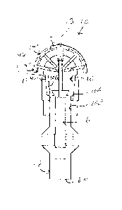
[0052] Referring to Fig. 1, there is shown an acetabular reamer 10 usable by
an
intended user (not shown in the drawings) for reaming an acetabulum (not shown
in the drawings). The acetabular reamer 10 includes a body 12, the body 12
defining a rotation axis 13 about which the acetabular reamer 10 is rotatable
by
the intended user.
[0053] The acetabular reamer 10 includes at least one reaming element 14, 14',
14". As described in further details hereinbelow, the acetabular reamer 10
shown
in the drawings includes a reaming element of a first type 14, four reaming
elements of a second type 14' and four reaming elements of a third type 14".
However, in alternative embodiments of the invention, the acetabular reamer 10
includes any suitable number of reaming elements 14, 14' and 14" and any
suitable number of types of reaming elements 14, 14', 14".
[0054] Each reaming element 14, 14' 14" is operatively coupled to the body 12
so
as to be movable between a respective reaming element inner position shown,
for
example, in Figs. 4a and 5a, and a respective reaming element outer position
shown, for example, in Figs. 4c and 5b, relatively to the body 12. Also, as
illustrated in Fig. 4b, each reaming element 14, 14', 14" may be moved at a
respective reaming element intermediate position located intermediate the
reaming element inner and outer positions. Each reaming element 14' and 14" is
positioned further away from the rotation axis 13 in the reaming element outer
position than in the reaming element inner position, except for the reaming
element 14 which moves substantially longitudinally away from the body 12 when
CA 02696990 2013-08-01
12
moving from the reaming element inner position to the reaming element outer
position.
[0055] As seen for example in Figs. 4a to 5b, the acetabular reamer 10 also
includes an actuator 16, the actuator 16 being operatively coupled to the body
12
and to the reaming elements 14, 14', 14" so as to allow the intended user (not
shown in the drawings) to move the reaming elements 14, 14' 14" between their
respective reaming element inner and outer positions.
[0056] A reaming element lock 18, shown for example in Figs. 2, 22a and 22b,
is
operatively coupled to the body 12 and to the reaming elements 14, 14' 14" so
as
to be configurable between a locked configuration, shown in Fig. 22a, and an
unlocked configuration, shown in Fig. 22b. In the unlocked configuration, the
reaming elements 14, 14', 14" are substantially free to move under the action
of
the actuator 16 between the reaming element inner and outer positions. In the
locked configuration, the reaming element lock 18 substantially prevents the
reaming elements 14, 14', 14" from moving relatively to the body 12.
[0057] Typically, the reaming element lock 18 is configured, sized and
operatively
coupled to the reaming elements 14, 14' and 14" and to the body 12 in a manner
such that when the reaming element lock 18 is in the locked configuration and
reaction forces are exerted onto the reaming elements 14, 14' and 14", for
example when the acetabular reamer 10 is used to ream the acetabulum (not
shown in the drawings), a larger portion of the reaction forces is transmitted
to the
body 12 than to the actuator 16. Typically, substantially all the reaction
forces are
transmitted directly to the body 12 by the reaming element lock 18.
CA 02696990 2013-08-01
13
[0058] Referring to Figs 5a and 5b, the body 12 defines a body proximal end
section 20, a substantially opposed body distal end section 22 and a body
intermediate section 24 extending therebetween. The body proximal end section
20 is attachable to a rotary power tool (not shown in the drawings) usable for
rotating the acetabular reamer 10 about the rotation axis 13. For example, the
body proximal end section 20 defines a power tool attachment 21, which may in
some embodiments take the form of a substantially elongated shaft, is
attachable
to a power drill (not shown in the drawings) in a conventional manner.
[0059] The body 12 defines a body recess 26 extending from the body distal end
section 22 substantially longitudinally into the body 12 towards the body
proximal
end section 20. The body recess 26 is provided for receiving the actuator 16
and
therefore allows mounting the actuator 16 to the body 12. The body recess 26
defines a recess aperture 28 in the body distal end section 22 leading into
the
body recess 26. The actuator 16 extends substantially longitudinally outwardly
from the body recess 26 through the recess aperture 28 and is mounted
thereinto
so as to be longitudinally movable relatively thereto. The body recess 26
defines a
recess end wall 30 located substantially opposed to the recess aperture 28 and
a
recess protrusion 32 extending substantially longitudinally from the recess
end
wall 30 towards the recess aperture 28.
[0060] The body 12 defines a body outer surface 33. An access aperture 34
extends substantially radially between the body outer surface 33 and the body
recess 26 and allows access to the actuator 16 so as to operate the actuator
16 to
move the reaming elements 14, 14', 14".
[0061] The body distal end section 22 defines locking component attachments 35
CA 02696990 2010-02-19
WO 2009/023972
PCT/CA2008/001525
14
for attaching the reaming element lock 18 to the body 12. For example, the
locking component attachments 35 take the form of protrusions formed into the
body distal end section 22, the protrusions tapering both in a direction
leading
towards the body proximal end section 20 and in direction leading towards the
body recess 26. For example, the locking component attachments 35 have a
substantially frustro-pyramidal configuration.
[0062] Still referring to Figs. 5a and 5b, the actuator 16 includes a reaming
element mounting portion 38 for mounting the reaming elements 14, 14' and 14"
thereto. A mounting portion support 40 is mounted to the body 12 and supports
the reaming element mounting portion 38. The mounting portion support 40 is
mounted to the body 12 so as to be substantially longitudinally movable
therealong
and allows mounting of the actuator 16 to the body 12. For
example, the
mounting portion support 40 is substantially elongated and extends
substantially
longitudinally from the reaming element mounting portion 38.
[0063] Referring to Figs. 20 and 21, the mounting portion support 40 defines a
support proximal end section 42 and a substantially longitudinally opposed
support
distal end section 44. For example, the mounting portion support 40 takes the
form of a substantially elongated component including a substantially
cylindrical
support distal end section 44 and a substantially cylindrical support proximal
end
section 42 extending therefrom. The support distal end section 44 typically
has
smaller diameter than the support proximal end section 42.
[0064] In some embodiments of the invention, the actuator 16 further includes
a
nut 46 mounted to the body 16 so as to extend into the access aperture 34 (not
shown in Figs. 20 and 21). As seen in Fig. 21, support threads 48 present in a
CA 02696990 2010-02-19
WO 2009/023972
PCT/CA2008/001525
threaded section 49 engage nut threads 50 of the nut 46 and are formed into
the
mounting portion support 40. For example the mounting portion support 40
defines
the threaded section 49 that extends substantially longitudinally therealong
into the
support proximal end section 42. The nut 46 is threaded onto the threaded
section
49 so as to be rotatable thereabout.
[0065] The nut 46 is operatively coupled to the body 12 so as to be
substantially
longitudinally substantially fixed relatively to the body 12. For example,
this is
achieved by providing a nut 46 that extends radially over a distance such that
the
nut 46 is prevented from entering into the body recess 26 outside of the
region
defines by the access aperture 34. Rotating the nut 46 relatively to the body
12
therefore moves the mounting portion support 40 substantially longitudinally
along
the body 12.
[0066] A rotation stopper 54 is provided for preventing the mounting portion
support 40 from rotating relatively to the body recess 26. For example, the
rotation stopper 54 takes the form of a slit extending longitudinally into the
support
proximal end section 42 and positioned, configured and dimensioned to engage
the recess protrusion 32 so as to be fixed in rotation about the rotation axis
13
relatively thereto.
[0067] Referring to Figs 6 and 7, the reaming element mounting portion 38
includes a radially central portion 52 from which arms 56 extend substantially
outwardly. Each of the arms 56 includes an arm first section 58 and an arm
second section 60 extending therefrom. The arm first section 58 extends from
the
radially central portion 52. The radially central portion 52, the arm first
sections 58
and the arm second sections 60 are provided for mounting thereto respectively
a
CA 02696990 2010-02-19
WO 2009/023972
PCT/CA2008/001525
16
reaming element of the first type 14, reaming elements of the second type 14'
and
reaming elements of the third type 14".
[0068] The arms 56 and the reaming elements 14, 14' and 14" are configured and
sized such that the reaming elements 14, 14' and 14" are moved between the
reaming element inner and outer portions when the mounting portion support 40
is
moved longitudinally along the body 12. Also, the mounting portion support 40
is
substantially longitudinally movable along the body 12 with the arms 56
keeping a
substantially constant circumferential orientation relatively to the body 12.
[0069] In the specific embodiment of the invention shown in the drawings, the
reaming element of the first type 14 extends substantially longitudinally away
from
the mounting portion support 40 from the radially central portion 52. In some
embodiments of the invention, the reaming element of the first type 14 is
removably mountable to the mounting portion support 40. In other embodiments
of
the invention, the reaming element of the first type 14 extends integrally
from the
mounting portion support 40. The reaming elements of the second type 14' are
each mounted to a respective arm first section 58 so as to be slidably movable
therealong and the reaming elements of the third type 14" are each mounted to
a
respective arm second section 60 so as to be slidably movable therealong.
[0070] It has been found that including four substantially circumferentially
equally
spaced apart arms 56 provides an acetabular reamer 10 producing relatively
small
amounts of vibration when used to ream the acetabulum. However, it is within
the
scope of the invention to include any suitable number of arms 56 in the
acetabular
reamer 10. Yet, furthermore, while the acetabular reamer 10 shown in the
drawings includes three types of reaming elements 14, 14' and 14" and includes
CA 02696990 2010-02-19
WO 2009/023972
PCT/CA2008/001525
17
arms 56 to which two reaming elements 14' and 14" are mountable, it is within
the
scope of the invention to have acetabular reamers 10 including arms 56 to
which
any other suitable number of reaming elements 14, 14' and 14" is mountable.
[0071] It has been found that having an arm first section 58 extending at an
angle
of about 113 degrees relatively to the rotation axis 13 and having an arm
second
section 60 extending at an angle of about 129 degrees relatively to the
rotation
axis 13 provides an acetabular reamer 10 able to produce relatively spherical
surfaces with a relatively large range of motion for the reaming elements 14,
14'
and 14". Therefore, the arms first and second sections 58 and 60 are angled
relatively to each other. Also, other values of the above-mentioned angles are
within the scope of the invention.
[0072] In some embodiments of the invention, a recess 62 is formed at the
junction between the arms first and second sections 58 and 60. The recess 62
extends towards the radially central portion 52 into the arm first section 58
and
increases the range of motion through which the reaming elements of the third
type 14" are movable along the arm second sections 60.
[0073] As mentioned hereinabove and seen in Fig. 18, the acetabular reamer 10
includes three types of reaming elements 14, 14' and 14". Each type of reaming
elements 14, 14' and 14" is mounted at a respective distance from the rotation
axis 13. The reaming element of the first type 14 is mounted to the radially
central
portion 52. Reaming elements of the second type 14' are mounted to the arm
first
sections 58 and reaming elements of the third type are mounted to the arm
second
sections 60. The arms 56 are substantially elongated and each define an arm
longitudinal direction. The reaming elements of the second and third types 14'
and
CA 02696990 2010-02-19
WO 2009/023972
PCT/CA2008/001525
18
14" are mounted to the arms 56 so as to be movable substantially
longitudinally
therealong and being substantially prevented from moving in any direction
substantially perpendicular to the arm longitudinal direction, as described in
further
details hereinbelow.
[0074] The reaming element of the first type 14 is better illustrated in Figs.
6 and
7. As seen in Fig. 6, the reaming element of the first type 14 includes a
reaming
element proximal end 64 and a reaming element distal end 66 substantially
opposed to the reaming element proximal end 64. The reaming element of the
first type 14 includes a reaming portion 68 located substantially adjacent the
reaming element distal end 66 and a reaming element-to-actuator coupling
portion
70 located substantially adjacent the reaming element proximal end 64. The
reaming portion 68 is provided for reaming the acetabulum of the patient for
which
a hip replacement surgery is performed. The reaming element-to-actuator
coupling portion 70 couples the reaming element of the first type 14 to the
actuator
16.
[0075] The reaming portion 68 defines a reaming surface 72, better shown, for
example, in Fig. 7. In a specific embodiment of the invention, the reaming
surface
72 is a cutting surface having a substantially smooth and substantially
arcuate
configuration. In the embodiment of the invention shown in the drawings, the
reaming surface 72 includes four substantially arcuate reaming surface
sections
74 each located eccentrically relatively to the rotation axis 13 and angled in
a
plane substantially perpendicular to the rotation axis 13 so as to be
substantially
perpendicular to each other.
[0076] In some embodiments of the invention, the reaming element of the first
CA 02696990 2010-02-19
WO 2009/023972
PCT/CA2008/001525
19
type 14 includes a point 79 (seen in Fig. 6 only), taking the form, for
example, of a
substantially conical element extending substantially longitudinally towards
the
reaming element distal end 66. The point 79 is usable for stabilizing the
acetabular reamer 10 about the rotation axis 13 when the acetabular reamer 10
is
used.
[0077] Referring to Figs. 8 to 11, there is shown in greater details the
reaming
element of the second type 14'. As seen in Fig. 11, the reaming element of the
second type 14' defines a reaming element proximal end 64' and an opposed
reaming element distal end 66'. The reaming element of the second type 14'
includes a reaming portion 68' for reaming the acetabulum of the patient and a
reaming element-to-actuator coupling portion 70' mechanically coupled to the
reaming portion 68'. For example, the reaming element-to-actuator coupling
portion 70' extends integrally from the reaming portion 68'.
[0078] The reaming element-to-actuator coupling portion 70' is mountable to
the
actuator 16 and, more specifically, to the arm first section 58, such that the
reaming element of the second type 14' is substantially longitudinally movable
therealong while substantially prevented from moving in any direction
perpendicular to the arm first section 58 relatively thereto. Therefore, the
reaming
element of the second type 14' is both actively deployable and retractable by
the
actuator 16.
[0079] For example, this is achieved through the use of a mounting aperture
76',
better seen in Figs. 8 and 11, extending through the reaming element-to-
actuator
coupling portion 70', the arm first section 58 extending through the mounting
aperture 76' when the reaming element of the second type 14' is mounted to the
CA 02696990 2010-02-19
WO 2009/023972
PCT/CA2008/001525
arm first section 58'.
[0080] As shown for example in Fig. 9, the reaming portion 68' defines a
radially
outward most reaming surface 72' taking the form, for example, of a cutting
surface
having a substantially smooth arcuate configuration. The reaming surface 72'
is
the portion of the reaming element of the second type 14' that reams the
acetabulum when the acetabular reamer 10 is in use.
[0081] As better seen in Fig. 11, the reaming element 14' defines
substantially
opposed abutment surfaces 80' and 82' located substantially opposed to each
other and extending between the reaming element proximal and distal ends 64'
and 66". The mounting aperture 76' is located between the abutment surfaces
80'
and 82'. The abutment surfaces 80' and 82' are provided for engaging the
reaming element lock 18 when the reaming element lock 18 is in the locked
configuration.
[0082] The reaming element of the second type 14' has a configuration such
that
mechanical interferences with adjacent reaming elements 14, 14' and 14" are
minimized so as to allow for a maximal range of motion along the arm first
section
58' of the reaming element of the second type 14'. The exact configuration of
the
reaming element of the second type 14' depends on the configuration of
adjacent
reaming elements 14, 14' and 14" and includes, for example, recesses 84' and
86'
located substantially adjacent the reaming element proximal end 64', the
recesses
84' and 86' being dimensioned to receive thereinto portions of adjacent
reaming
elements 14, 14', 14" at predetermined positions of the reaming elements 14,
14',
14" between the reaming element inner and outer positions.
CA 02696990 2010-02-19
WO 2009/023972
PCT/CA2008/001525
21
[0083] In addition, as better seen in Fig. 8, the reaming element of the
second
type 14' defines bevelled surfaces 88' and 90' located respectively adjacent
the
reaming element proximal and distal ends 64' and 66'. The bevelled surfaces
88'
and 90' are configured to provide a space through which adjacent reaming
elements 14, 14' and 14" are insertable.
[0084] Figs. 12 to 15 illustrate the reaming element of the third type 14".
The
reaming element of the third type 14" has a configuration that is
substantially
similar to the configuration of the reaming element of the second type 14',
and is
therefore not described in greater details. In Figs. 12 to 15, reference
numerals
having a " suffix designate sections, portions and structures of the reaming
element of the third type 14" having a function similar to the function of
sections,
portions and structures of the reaming element of the second type 14' having
the
same numerical designation to which a 'suffix has been added. More
specifically,
the reaming element 14" defines reaming element proximal and distal ends 64"
and 66", reaming portion 68", reaming element-to-actuator coupling portion
70',
reaming surface 72"and mounting aperture 76".
[0085] As shown in Fig. 16, in some embodiments of the invention, the reaming
surfaces 72, 72' and 72" are not cutting surfaces but instead a grating
surfaces.
Therefore, in these embodiments, the reaming elements 14, 14', 14", for
example
the alternative reaming element of the second type 14" shown in Fig. 16,
include
an alternative reaming surface 74" defining asperities 92 extending therefrom
substantially away from the reaming element-to-actuator coupling portion 70'.
[0086] Figure 17 illustrates the manner in which the reaming elements 14, 14',
14" are mounted to the reaming element mounting portion 38. As seen in this
CA 02696990 2010-02-19
WO 2009/023972
PCT/CA2008/001525
22
Figure, the reaming surfaces 72, 72' and 72" of the reaming elements of the
first
second and third types 14, 14' and 14" are distributed along at least one
meridian
of a substantially spherical-cap-shaped surface rotatable about the rotation
axis 13
with their reaming surfaces 72, 72' and 72" having a substantially smooth and
substantially arcuate configuration oriented along the at least one meridian.
In
some embodiments of the invention, the reaming portions 68, 68' and 68" are
each substantially arc-segment shaped and extend over a length such that
reaming portions 68, 68' and 68" of reaming elements 14, 14' and 14" located
on
a common meridian substantially overlap. To that effect, adjacent reaming
portions
68, 68' and 68" located on a common meridian are substantially
circumferentially
slightly offset from each other.
[0087] The reaming portions 68, 68' and 68" are shaped and dimensioned such
that the global reaming surface formed thereby is formed on a substantially
spherical cap (not shown in the drawings). It has been found that having an
acetabular reamer 10 having a dimension and a configuration such that this
spherical cap (not shown in the drawings) has a radius of curvature varying
from
about 44 mm to about 66 mm provides an acetabular reamer 10 suitable for use
in
most hip replacement surgeries. Advantageously, the proposed acetabular reamer
then has a ratio of about 1.5 between the radius of the smallest reamable
cavity
and the largest reamable cavity, which is relatively large when compared to
existing acetabular reamers.
[0088] In some embodiments of the invention, the reaming portions 68, 68' and
68" of reaming elements 14, 14' and 14" located on a same meridian
substantially
overlap over the entire range of motion of the reaming elements 14, 14' and
14".
However, in alternative embodiments of the invention, there is no such overlap
and, in yet other embodiments of the invention, the reaming elements 14, 14'
and
CA 02696990 2010-02-19
WO 2009/023972
PCT/CA2008/001525
23
14", overlap only over a portion of the range of motion of the reaming
elements 14,
14' and 14". This overlap allows for the production of a relatively smooth
surface
when reaming the acetabulum of a patient without requiring that the acetabular
reamer 10 be moved in a substantially ball-joint-like motion inside the
patient.
[0089] As seen in Figs. 19, 22a and 22b, the reaming element lock 18 includes
substantially circumferentially spaced apart locking components 36 mounted to
the
body 12 so as to be movable between a locked position, shown in Fig. 22a, and
an
unlocked position, shown in Fig. 22b. The reaming element lock 18 includes at
least two locking components 36. In the embodiment of the invention shown in
the
drawings, the reaming element lock 18 includes four locking components 36. The
locking components 36 define substantially circumferentially extending gaps 37
therebetween. As detailed hereinbelow, the reaming elements of the second and
third types 14' and 14" are partially inserted in the gap 37. The reaming
element
lock 18 also includes a lock actuating element 104 operatively coupled to the
locking components 36 for configuring the reaming element lock 18 between the
locked and unlocked configurations.
[0090] In the unlocked position, the reaming element lock 18 is in the
unlocked
configuration, and the locking components 36 are spaced apart by a larger
distance than in the locked position. When the locking components 36 are in
the
locked position, the reaming element lock 18 is in the locked configuration.
The
locking components 36 frictionally engage the reaming elements of the second
and third types 14' and 14" when the locking components 36 are in the locked
position.
[0091] Fig. 18 illustrates one of the locking components 36 to which a reaming
CA 02696990 2010-02-19
WO 2009/023972
PCT/CA2008/001525
24
element of the second type 14" is mounted. The locking component 36 defines a
locking component distal end 101 and an opposed locking component proximal
end 99. The locking component 36 also defines a locking component radially
outwardmost surface 94 and two locking component lateral surfaces 96 and 97
extending therefrom, the two locking components lateral surfaces 96 and 97
sharing a common edge 100 and being angled at an angle of about 90 degrees
relatively to each other. When the locking component 36 is mounted to the body
12, the locking component radially outwardmost surface 94 faces outwardly. The
locking component 36 includes a locking component actuating portion 112 for
coupling the locking component 36 to the lock actuating element 104 (not shown
in
Fig. 18).
[0092] The locking component radially outwardmost surface 94 has a
substantially arcuate configuration and the locking component lateral surfaces
96
and 97 have a substantially planar configuration. Therefore, the four locking
components 36, when put adjacent to each other so that their respective
locking
component lateral surfaces 96 and 97 extend substantially parallel to each
other
form a structure having a rotational symmetry with the locking component
radially
outwardmost surfaces 94 facing substantially radially outwardly.
[0093] In some embodiments of the invention, the locking component actuating
portion 112 includes a portion of the locking component 36 extending from the
locking component proximal end 99 towards the locking component distal end
101.
The locking component actuating portion 112 includes a portion of locking
component radially outwardmost surface 94 shaped similarly to an arc segment
of
a substantially frustro-conical surface and tapers in a direction leading
towards the
locking component proximal end 99.
CA 02696990 2010-02-19
WO 2009/023972
PCT/CA2008/001525
[0094] Grooves 98, 98' and 98" are formed into the locking component 36 for
slidably receiving respectively a portion of the reaming elements of the
first,
second and third types 14, 14' and 14" thereinto for mounting the reaming
elements 14, 14' and 14" thereto and guiding the reaming elements 14, 14' and
14" therealong when the reaming elements 14, 14' and 14" are moved between
said reaming element inner and outer positions. The groove 98 extends
substantially longitudinally and is provided for receiving a portion of the
reaming
element of the first type 14. The grooves 98' extend at an angle of about 44
degrees relatively to the rotation axis 13 and have a substantially U-shaped
configuration for receiving thereinto a portion of the reaming element of the
second
type 14'. More specifically, the grooves 98' are provided for each
frictionally
engaging one of the abutment surfaces 82' and 80' of the reaming elements of
the
second type 14'. The grooves 98" extend at an angle of about 78 degrees
relatively to the rotation axis 13 and have a substantially U-shaped
configuration
for receiving thereinto a portion of one of the reaming elements of the third
type
14". More specifically, the grooves 98" are provided for each frictionally
engaging
one of the abutment surfaces 82" and 80" of the reaming elements of the third
type 14".
[0095] As seen in Figs. 22a and 22b, and as mentioned hereinabove, the locking
components 36 are mountable to the body 12 so as to be movable between a
locked position and an unlocked position. In the locked position, the locking
components abut against and frictionally engage the abutment surfaces 80',
82',
80" and 82" and the reaming element of the first type 14, and therefore
frictionally
prevent movement of the reaming elements 14, 14' and 14" relatively to the
locking components 36. In the unlocked position, the locking components 36 are
spaced apart by a large distance than in the locked position, thereby
releasing a
grip exerted onto the reaming elements 14, 14' and 14".
CA 02696990 2010-02-19
WO 2009/023972
PCT/CA2008/001525
26
[0096] Referring to Fig. 18, in some embodiments of the invention, each
locking
component 36 defines a guiding groove 102 for mounting the locking component
36 to the locking component attachment 35. For example, the guiding groove 102
bisects and extends from the intersection of the locking component lateral
surfaces 96 and 97 towards the locking component radially outwardmost surface
94 substantially midway between the locking component lateral surfaces 96 and
97 and substantially adjacent to the locking component proximal end 99. The
guiding groove 102 is tapered both in a direction loading towards the locking
component proximal end 99 and in a direction loading towards the locking
component radially outwardmost surface 94. The locking component attachments
35 take the form of protrusions having a shape complementary to the guiding
grooves 102 and are received within the guiding groove 102.
[0097] In some embodiments of the invention, the lock actuating element 104
takes the form of a sleeve mounted to the body 12 so as to be substantially
longitudinally movable relatively thereto. The lock actuating element 104 is
also
operatively coupled to the locking components 36 so as to move the locking
components 36 between the locked positions and the unlocked positions. As seen
in Fig. 3, the lock actuating element 104 defines a locking component mounting
passageway 106 extending substantially longitudinally and a body mounting
passageway 108 extending substantially longitudinally therefrom.
[0098] The locking component actuating portions 112 of the locking components
36 are at least partially located in the locking component mounting passageway
106, the locking component mounting passageway 106 engaging the locking
components 36 in a manner such that the locking components 36 are moved
between the locking component locked and unlocked positions when the lock
actuating element 104 is moved substantially longitudinally along the body 12.
CA 02696990 2010-02-19
WO 2009/023972
PCT/CA2008/001525
27
[0099] For example, the locking component mounting passageway 106 is
substantially frustro-conical and has a substantially tapered configuration in
a
direction leading towards the body proximal end section 20. The locking
component mounting passageway 106 is substantially parallel to the actuating
portion radially outwardmost surfaces 94. The body mounting passageway 108
has a substantially cylindrical configuration for mounting to a portion of the
body
12 having a substantially cylindrical configuration having a similar diameter.
[00100] In some embodiments of the invention, the lock actuating element 104
is
slidably mounted to the body 12. However, in alternative embodiments of the
invention, the lock actuating element 104 is mountable to the body 12 in any
other
suitable manner allowing the lock actuating element 104 to move substantially
longitudinally relatively to the body 12. For example, lock actuating element
104
may be screwable onto the body 12 through the use of threads formed both into
the lock actuating element 104 and into the body 12 (this variant not being
illustrated).
[00101] The lock actuating element 104 is movable between a proximal position
and a distal position. In the proximal position (seen for example in Fig.
22b), the
locking component mounting passageway 106 is positioned such that the locking
components 36 are spaced apart by a larger distance than in the distal
position. In
the distal position (seen for example in Fig. 22a), the locking component
mounting
passageway 106 biases the locking components 36 towards each other.
[00102] In use, the intended user (not shown in the drawings) positions the
lock
actuating element 104 in the proximal position and the locking components 36
in
the unlocked positions. This reduces the friction exerted by the locking
CA 02696990 2010-02-19
WO 2009/023972
PCT/CA2008/001525
28
components 36 onto the reaming elements 14, 14' and 14", and allows the
intended user (not shown in the drawings) to use the actuator 16 to position
the
reaming elements 14, 14' and 14" in their reaming element inner positions.
Subsequently, the locking components 36 are moved to their locked positions by
moving the lock actuating element 104 to the distal position, and the
acetabular
reamer 10 is inserted in the body of the patient. Reaming is then performed.
When there is a need to expand the dimension of the acetabular reamer 10, the
intended user (not shown in the drawings) leaves the acetabular reamer inside
the
patient and adjusts the position of the reaming elements 14, 14', 14" as
described
hereinabove such that the reaming elements 14, 14', 14" are moved over a
desired distance towards their reaming element outer positions.
[00103] In the embodiment of the invention shown in the drawings, this is
achieved by rotating the nut 46, thereby translating the actuator 16
relatively to the
body 12, which consequently moves the reaming elements 14, 14' and 14"
relatively to the locking components 36 and relatively to the body 12. This is
achieved because the arm first and second sections 58 and 60 are substantially
rectilinear and angled relatively to the rotation axis 13. For example, the
thread
count on the nut 46 and body 12 is such that a predetermined fraction of a
whole
turn of the nut 46 results in a convenient predetermined expansion the reaming
elements 14, 14', 14". For example, each turn of the nut 46 corresponds to a
movement of about 1 mm of the reaming elements 14, 14' and 14" respectively
relatively to the grooves 98, 98' and 98".
[00104] Once a suitable position for the reaming elements 14, 14' and 14" has
been achieved, the locking component 36 is configured into the locked
configuration by moving the lock actuating element 104 away from the body
proximal end section 20, which guides the locking components 36 towards each
CA 02696990 2010-02-19
WO 2009/023972
PCT/CA2008/001525
29
other. In this configuration, the reaming elements 14, 14' and 14" are
supported
by the locking components 36 and, therefore, only relatively small forces are
transmitted to the actuator 16 by the reaming elements 14, 14' and 14".
[00105] In alternative embodiments of the invention, the actuator 16 takes any
other suitable form. For example, the actuator 16 is configured so as to be
operable further away from the reaming elements 14, 14' and 14" than in the
acetabular reamer 10. Also, in some embodiments of the invention, a handle
(not
shown in the drawings) is provided for allowing a surgeon to handle the
acetabular
reamer 10 relatively easily and precisely.
[00106] In an alternative embodiment of the invention shown in Fig. 23, an
alternative actuator 16' defines a deployment indicator 110 for moving the
actuator
16' in discrete steps so as to move the reaming elements 14, 14' and 14" in
(all not
shown in Fig. 23) discrete steps relatively to the rotation axis 13 (not shown
in Fig.
23). For example, the deployment indicator 110 includes a tactile deployment
indicator. An example of such a tactile deployment indicator 110 takes the
form of
a nut 46' including substantially longitudinally extending protrusions 113.
The nut
46' is mounted in an access aperture 34 allowing relatively small movements of
the nut 46' longitudinally therealong. The body 12 defines longitudinally
extending
recesses 114 for receiving the protrusions 113. The nut 46' is biased towards
the
recesses 114 by a biasing element 116, for example taking the form of a coil
spring. Therefore, as the nut 46' is rotated, when predetermined angular
positions
of the nut 46' are reached, the protrusions 113 engage the recesses 114, which
transmits a small impact force to the intended user through the nut 46 and
indicates that the predetermined angular position has been reached. To
continue
rotating the nut 46', the intended user exerts a force large enough on the nut
46'
so that the protrusions 113 are pushed out of the recesses 114.
CA 02696990 2010-02-19
WO 2009/023972
PCT/CA2008/001525
[00107] Figures 24 to 29 illustrate an alternative reaming element mounting
portion 238 and an alternative reaming element of the second type 214. The
reaming element mounting portion 238 is similar to the reaming element
mounting
portion 38 described hereinabove and includes a radially central portion 252
from
which arms 256 extend substantially outwardly. Each of the arms 256 includes
an
arm first section 258 and an arm second section 260 extending therefrom. The
arm first section 258 extends from the radially central portion 252. However,
instead of having a substantially rectangular cross-section, the arm first
section
258 has a substantially trapezoidal transversal cross-sectional configuration.
The
arm first section 258 is provided for mounting the alternative reaming element
of
the second type 214.
[00108] Referring to Figs. 26 to 29, there is shown in greater details the
alternative reaming element of the second type 214. As seen for example in
Fig.
28, the reaming element of the second type 214 defines a reaming element
proximal end 264 and an opposed reaming element distal end 266. The reaming
element of the second type 214 includes a reaming portion 268 for reaming the
acetabulum of the patient and a reaming element-to-actuator coupling portion
270
mechanically coupled to the reaming portion 268. For example, the reaming
element-to-actuator coupling portion 270 extends integrally from the reaming
portion 268.
[00109] The reaming element-to-actuator coupling portion 270 is mountable to
the
to the arm first section 258 such that the reaming element of the second type
214
is substantially longitudinally movable therealong while substantially
prevented
from moving in any direction perpendicular to the arm first section 258
relatively
thereto. Therefore, the reaming element of the second type 214 is both
actively
deployable and retractable by the arm first section 258.
CA 02696990 2013-08-01
31
[00110] For example, this is achieved through the use of a mounting groove
276,
better seen in Figs. 26 and 29, extending into the reaming element-to-actuator
coupling portion 270 from reaming element proximal end 264. The mounting
groove
276 includes a groove proximal section 278 and a groove distal section 280.
The
groove distal section 280 is spaced apart from the reaming element distal end
266
and has a substantially trapezoidal lateral cross-sectional configuration
tapering
towards the reaming element distal end 266 that is substantially similar to
the lateral
cross-sectional configuration of the arm first section 258. The groove distal
section
280 is mountable to the arm first section 258 so as to be substantially
longitudinally
movable therealong. The groove proximal section 278 extends between the
reaming
element proximal end 264 and the groove distal section 280 and is configured
for
allowing free movement of the arm second section 260 therethrough. For
example,
the groove proximal section 278 has a substantially rectangular cross-
sectional
configuration. The mounting groove 276 is advantageous in some embodiments of
the invention as the open nature of the proximal extremity of the mounting
groove
276 allow for manufacturing a relatively compact acetabular reamer 10.
[00111] The reaming portion 268 is substantially similar to the reaming
portion 68'
and, with the exception of the mounting groove 276 replacing the mounting
aperture
76', the reaming element-to-actuator coupling portion 270 is substantially
similar to
the reaming element-to-actuator coupling portion 70'. These elements will
therefore
not be described in further details herein.
[00112] Although the present invention has been described hereinabove by way
of
examples thereof, many modifications are possible in the examples without
materially departing from the novel teachings and advantages of this
invention.
Accordingly, the scope of the claims should not be limited by the examples,
but
should be given the broadest interpretation consistent with the description as
a
whole.