Note: Descriptions are shown in the official language in which they were submitted.
CA 02697131 2011-08-23
MUNTIN GRIDS FOR TRANSPARENCIES AND
TRANSPARENCIES HAVING MUNTIN GRIDS
BACKGROUND OF THE INVENTION
1.) Field of the Invention
[0001] This invention relates to muntin grids for transparencies and to
transparencies having muntin grids, and more particularly, to a grid
simulating
muntins having shaped ends to engage spacer frame between glass sheets of
a multi-sheet unit to mount the grid within the spacer frame and between the
glass sheets.
2.) Discussion of the Available Technology
[0002] Clips usually referred to as '""muntin clips" are used to mount
grids simulating muntins between adjacent sheets of a multi-sheet insulating
unit, for example, as discussed in U.S. Patent Nos. 5,313,761 and 6,115,989;
United States Patent Publication Numbers US2004/0123557 and
US2005/0028458A1 and in U.S. Patent No. 7,954,284. In
general, but not liming to the discussion, a multi-sheet insulating unit
includes
a glass sheet secured to each side of a spacer frame by a moisture and gas
impervious adhesive-sealant to provide a sealed compartment between the
sheets. The sealed compartment is usually filled with an insulating gas. The
spacer frame in one embodiment of a multi-sheet insulating unit has a U-
shaped cross section, e.g. as disclosed in U.S. Patent No. 5,655,282. One of
the features of the spacer frame having a U-shaped cross section is that the
upright legs of the spacer frame are free to move toward and away from one
another in unison with the glass sheets as the insulating gas in the
compartment between the sheets expands and contracts due to pressure
changes acting on the outer surfaces of the sheets.
[00031 The current practices of mounting a grid simulating muntins
within the spacer frame, includes mounting the muntin clips on the ends of the
grid, and mounting the clips on the interior surface of the spacer frame, or
-1-
CA 02697131 2011-08-23
mounting the muntin clips on the interior surface of the spacer frame followed
by mounting the ends of the grid on the muntin clips. United States Patent
Application Publication Number US 2004/0123557 discloses a number of
muntin clip designs- Although the present design of the muntin clips is
acceptable for mounting grids simulating muntins between sheets of insulating
units, there are drawbacks and/or limitations.
[0004] More particularly, many of the present muntin clips designs
include a rigid base that bridges the two upright legs of the spacer frame
maintaining the upright legs in a fixed relationship to one another. The
drawback with this muntin clip design is that the muntin clip prevents
portions
of the upright legs and marginal edges of the sheets from moving toward one
another as the pressure acting on the outside surface of the sheets increases.
Another drawback with muntin clips having a rigid base is that during the
pressing of the marginal edges of the sheets toward the outer surfaces of the
space frame to flow the adhesive-sealant between the sheets and the spacer
frame, the upright legs between adjacent muntin clips are flexible and move
toward one another whereas the muntin clip is not flexible and prevents the
upright legs at the position of the muntin clip from moving toward one
another.
The undesirable result is that the adhesive-sealant between adjacent muntin
clips is thicker than the thickness of the adhesive-sealant at the position of
the
muntin clips. This drawback results in a "moisture sealant path" or "diffusion
path" having a non-uniform thickness and can result in premature failure of
the seal by allowing atmospheric air to diffuse into the sealed compartment.
For a detailed discussion of the "diffusion path," reference can be made to
column 13, lines 7-43 of U.S. Patent No. 5,655,282.
[0005] Another limitation with having the base of the muntin clip
supported on and spanning the upright legs of the spacer frame is that the
muntin clip is in the sight line of the insulating unit. Therefore, care has
to be
taken to make certain that the ends of the grid simulating muntins is flush
with
the base to avoid any space, or minimize the space, between the ends of the
grid and the base of the muntin clip. Noticeable separations between the
base of the clip and the end of the grid are aesthetically unacceptable.
-2-
CA 02697131 2011-08-23
[0006] US Patent No. 7,954,284 discloses a muntin clip that eliminates
the above drawbacks. More particularly, this muntin clip has a spacer-engaging
member having bendable walls that are positioned between the upright legs of
the
spacer frame with the end of the grid simulating muntins below the sight line
of the
unit. Although this muntin clip eliminates the above discussed drawbacks, it
has
limitations. More particularly, muntin clips are required to secure the grid
within the
spacer frame. As is appreciated by those skilled in the art, the open ends of
the
horizontal and vertical members of the grids simulating muntins have different
dimensions requiring an inventory of different size muntin clips for the
different
size end openings of the horizontal and vertical members.
[0007] As is appreciated by those skilled in the art, it would be advantageous
to provide a grid simulating muntins that does not require the use muntin
clips
and provides the benefits of the muntin clips of US Patent No. 7,954,284.
SUMMARY OF THE INVENTION
[0008] This invention relates to a grid simulating muntins of the type
having a first plurality of spaced elongated members connected to a second
plurality of elongated members, wherein one of the elongated members of the
first plurality of elongated members. In one non-limiting embodiment of the
invention, the grid simulating muntins includes a first side having an outer
surface; a second side opposite the first side, the second side having an
outer
surface facing away from the outer surface of the first side; a first end, and
an
opposite second end. The first and second sides at the first end each have
an end part, wherein the end part of the first side is angled toward the outer
surface of the first side and the end part of the second side is angled toward
the outer surface of the second side, and ends of the end parts of the first
and
second sides at the first end of the one of the elongated members are each
shaped to have a ]edge.
[0009] The invention further relates to a multi-sheet unit having the grid
of the invention simulating muntins. In one on-limiting embodiment of the
invention, the multi-sheet unit includes a spacer frame having a base, a pair
of
legs extending from the base toward interior of the spacer frame, and an
-3-
CA 02697131 2010-02-19
WO 2009/032659 PCT/US2008/074379
interior side facing interior of the spacer frame; a pair of sheets, wherein
the
spacer frame is between the sheets and the sheets are mounted on outer
surface of the pair of legs. The grid simulating muntins is in the interior of
the
spacer frame between the sheets, the grid includes a first plurality of spaced
elongated members, and a second plurality of spaced elongated members.
Each of the first plurality of elongated members and each of second plurality
of elongated members includes a first side having an outer surface; a second
side opposite the first side, the second side having an outer surface; a first
end, and an opposite second end, the first and second sides at the first end
each have an end part, wherein the end part of the first side and the end part
of the second side are each angled toward the second end, the outer surface
of the first side on the end part of the first side in facing relationship to
the
outer surface of the second side on the end part of the second side, and the
ends of the end parts of the first and second sides at the first end are each
shaped to have a ledge, and the first side and the second side at the second
end each have an end part, wherein the end part of the first side and the end
part of the second side at the second end are each angled toward the first
end, the outer surface of the first side on the end part of the first side at
the
second end in facing relationship to the outer surface of the second side on
the end part of the second side at the second end, and the ends of the end
parts of first and second sides at the second end are each shaped to have a
ledge.
[0010] The ledge of the end part of the first side and the ledge of the
end part of the second side at the first end of each of the first plurality of
elongated members engages a first length of the interior side of the spacer
frame, and the portion of the end part of the first side and of the second
side
at the first end of the first plurality of elongated members is between the
interior side and inner surface of the base of the spacer frame; the ledge of
the end part of the first side and the ledge of the end part of the second
side
at the second end of each of the first plurality of elongated members engages
a second length of the interior side of the spacer frame, the second length
opposite to the first length, and the portion of the end part of the first
side and
of the second side at the second end of the first plurality of elongated
members is between the interior side and the inner surface of the base of the
-4-
CA 02697131 2010-02-19
WO 2009/032659 PCT/US2008/074379
spacer frame; the ledge of the end part of the first side and the ledge of the
end part of the second side at the first end of each of the second plurality
of
the elongated members engages a third length of the interior side of the
spacer frame, and the portion of the end part of the first side and of the
second side at the first end of the second plurality of elongated members is
between the interior side and the inner surface of the base of the spacer
frame, and the ledge of the end part of the first side and the ledge of the
end
part of the second side at the second end of each of the second plurality of
elongated members engages a fourth length of the interior side of the spacer
frame, the fourth length opposite the third length, and the portion of the end
part of the first side and of the second side at the second end of the second
plurality of elongated members is between the interior side and the inner
surface of the base of the spacer frame.
[0011] The invention still further relates to a method of making a grid
simulating muntins. In a non-limiting embodiment of the invention the method
includes providing a first plurality of elongated members and a second
plurality of elongated members, each of the elongated members having a first
side, a second side, a third side and a fourth side with the first side and
the
second side opposite to one another, the third side opposite to the fourth
side
opposite to one another and between the first and second sides, a first end
and an opposite second end; removing a portion of the third side and the
fourth side at the first end of one of the plurality of elongated members
defined as a first elongated member to provide the first side with an end part
and the second side with an end part at the first end of the first elongated
member; bending the end part of the first side at the first end toward the
second end of the first elongated member, and bending the end part of the
second side at the first end toward the second end of the first elongated
member; shaping free end of the end part of the first side to form a ledge and
free end part of the second side to form a ledge, and joining the first and
second plurality of elongated members to form the grid simulating muntins.
-5-
CA 02697131 2010-02-19
WO 2009/032659 PCT/US2008/074379
BRIEF DESCRIPTION OF THE DRAWINGS
[0012] Fig. 1 is a plan view of a multi-sheet unit incorporating features
of the invention.
[0013] Fig. 2 is a view taken along lines 2-2 of Fig. 1.
[0014] Fig. 3 is a view taken along lines 3-3 of Fig. 1.
[0015] Fig. 4 is an orthogonal view of a section of a non-limiting
embodiment of a spacer frame that can be used in the practice of the
invention.
[0016] Fig. 5 is a view similar to the view of Fig. 4 showing a section of
another non-limiting embodiment of a spacer frame that can be used in the
practice of the invention.
[0017] Fig. 6 is front view of an end section of an elongated member of
a grid simulating muntins, the elongated member incorporating features of the
invention.
[0018] Fig. 7 is a view taken along lines 7-7, of Fig. 6, and Fig. 7A is an
enlarged view of the circled portion of Fig. 7.
[0019] Fig. 8 is a view taken along lines 8-8, of Fig. 6, and Fig. 8A is an
enlarged view of the circled portion of Fig. 8.
[0020] Fig. 9 is a view along lines 9-9 of Fig. 4 showing the elongated
member of Fig. 6 mounted on the section of the spacer frame shown in Fig. 4.
[0021] Figs. 10-13 are different views showing non-limiting
configurations of the end section of an elongated member of a grid of the
invention after the practice of non-limiting operations of the invention to
shape
the end of the member in accordance to the teachings of the invention.
DESCRIPTION OF THE INVENTION
[0022] As used herein, spatial or directional terms, such as "inner",
"outer", "left", "right", "up", "down", "horizontal", "vertical", and the
like, relate to
the invention as it is shown in the drawing figures. However, it is to be
understood that the invention can assume various alternative orientations
and, accordingly, such terms are not to be considered as limiting. Further,
all
numbers expressing dimensions, physical characteristics, and so forth, used
in the specification and claims are to be understood as being modified in all
instances by the term "about". Accordingly, unless indicated to the contrary,
-6-
CA 02697131 2010-02-19
WO 2009/032659 PCT/US2008/074379
the numerical values set forth in the following specification and claims can
vary depending upon the desired properties sought to be obtained by the
present invention. At the very least, and not as an attempt to limit the
application of the doctrine of equivalents to the scope of the claims, each
numerical parameter should at least be construed in light of the number of
reported significant digits and by applying ordinary rounding techniques.
Moreover, all ranges disclosed herein are to be understood to encompass any
and all subranges subsumed therein. For example, a stated range of "1 to 10"
should be considered to include any and all subranges between (and inclusive
of) the minimum value of 1 and the maximum value of 10; that is, all
subranges beginning with a minimum value of 1 or more and ending with a
maximum value of 10 or less, e.g., 1 to 6.7, or 3.2 to 8.1, or 5.5 to 10.
Also,
as used herein, the terms "mounted over", "positioned over", or "provided
over" mean mounted, positioned, or provided on but not necessarily in surface
contact with. For example, one article "provided over" another article does
not
preclude the presence of materials between the articles.
[0023] Before discussing non-limiting embodiments of the invention, it
is understood that the invention is not limited in its application to the
details of
the particular non-limiting embodiments shown and discussed herein since
the invention is capable of other embodiments. Further, the terminology used
herein to discuss the invention is for the purpose of description and is not
of
limitation. Still further, unless indicated otherwise, in the following
discussion
like numbers refer to like elements.
[0024] In general, the non-limiting embodiments of the invention
include, but are not limited to, securing grids simulating muntins between
sheets, e.g. adjacent sheets, of multi-sheet units without the use of muntin
clips by shaping the ends of the horizontal and vertical members of the grid
in
accordance to the teachings of the invention. The term "multi-sheet unit" is
usually used to mean a unit having two or more sheets in spaced relationship
to one another, and the term "multi-sheet insulating unit" is usually used to
mean a unit having two or more sheets in spaced relationship to one another
and a compartment or space between adjacent sheets in which there is an
insulating gas and preferably no or limited ingress or egress of gas into
and/or
out of the compartment, usually referred to as a "sealed compartment." In the
-7-
CA 02697131 2011-08-23
following discussion, the term "multi-sheet unit", unless indicated otherwise,
is
used to mean a "multi-sheet unit" and a "multi-sheet insulating unit."
[0025] As can be appreciated, the practice of the invention is not limited
to a multi-sheet unit and can be practiced on a transparency having only one
sheet, with the one sheet secured to one side of a spacer frame; no sheet
secured to the opposite side of the spacer frame, and the grid of the
invention
simulating muntins mounted within the spacer frame.
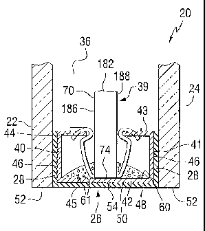
[0026] Fig. 1 shows a multi-sheet unit 20 incorporating features of the
invention, and Figs. 2 and 3 show cross sectional views of the multi-sheet
unit 20. The unit 20 has a pair of outer sheets 22 and 24 secured to a spacer
frame 26 by a layer 28 of an adhesive or moisture impervious adhesive-
sealant to provide a compartment 36 between the sheets 22 and 24.
Preferably, but not limiting to the invention, the compartment 36 is sealed
against the egress and ingress of the atmosphere outside the compartment,
e.g., gases, moisture and/or dust (hereinafter individually and collectively
referred to as "environmental atmosphere") by the layers 28 of the adhesive
sealant discussed in more detail below. A grid 39 simulating muntins and
incorporating features of the invention is provided in the compartment 36,
i.e.
within the spacer frame 26, between the sheets 22 and 24 in accordance to
the teachings of the invention.
[0027] The invention is not limited to the material of the sheets 22
and 24 of the multi-sheet unit 20 of the invention, and the sheets can be made
of any transparent material, e.g. glass, plastic and combinations thereof, and
the selection of the material of the sheets is not limiting to the invention.
Still
further, the two or more sheets of the multi-sheet unit can be made of the
same material or the sheets can be made of different materials. In addition,
one sheet can be a monolithic sheet, and the other sheet can be a laminate,
e.g. a transparency made of one or more monolithic sheets laminated
together in any usual manner. One or both of the glass sheets of the unit can
be uncoated and/or coated, and/or one or both of the sheets can be colored
and/or clear sheets. For example and not limiting to the invention, the
colored
sheets can be of the type disclosed in U.S. Patent Nos. 4,873,206; 4,792,536;
5,030,593 and 5,240,886. Further, one or more of the
surfaces of one or more of the sheets
-8-
CA 02697131 2011-08-23
can have a coating to selectively pass predetermined wavelength ranges of
light and energy, or one of the sheets can be opaque, e.g. made of an opaque
material, e.g. metal, or can be transparent sheets having an opaque coating
of the type used in making spandrels. Coatings of the type that can be used
in the practice of the invention include but are not limited to the types
disclosed in U.S. Patent Nos. 4,170,460; 4,239,816; 4,462,884; 4,610,711;
4,692,389; 4,719,127; 4,806,220; 4,853,256 and 4,898,789. Still
further, in the practice of the non-limiting embodiments of the invention,
one or more of the surfaces of the sheets can have a photocatalytic film or
water reducing film, e.g. of the type disclosed in U.S. Patent Nos. 5,873,203
and 6,027,766. It is contemplated that the photocatalytic film
and/or the water reducing film can be applied or deposited on the outer
surface of one or both of the sheets 22 and 24 of the multi-sheet unit 20.
[0028] The glass sheets 22 and 24 preferably have the same peripheral
configuration and dimensions; however, as can be appreciated, one outer
glass sheet can be larger than the other outer glass sheet. Further, the outer
sheets 22 and 24 can have different peripheral configurations.
[0029] With continued reference to Figs. 2 and 3, in the non-limiting
embodiment of the invention under discussion, the spacer frame 26 has a pair
of spaced outer legs 40 and 41 secured to a base 42 to have a generally U-
shaped cross sectional configuration. Each of the outer legs 40 and 41 have a
ledge or extension 44 and 43, respectively, extending toward one another
over inner surface 45 of the base 42. The layer 28 of adhesive is provided on
outer surface 46 of the legs 40 and 41 of the spacer frame 26 to secure the
outer sheets 22 and 24 to the legs 40 and 41, respectively, of the spacer
frame 26 to seal the compartment 36 against movement of environmental
atmosphere into and out of the compartment. The layer 28 is preferably a
moisture-impervious adhesive-sealant of the type used in the art to seal
compartments of insulating units, and includes but is not limited to, butyls,
silicones, polyurethane adhesives, and butyl hot melts of the type sold by
PPG Industries, Inc. e.g. PRC591 SB. For a more detailed discussion of
materials that can be used in the practice of the invention, but not limited
-9-
CA 02697131 2011-08-23
thereto, reference is made to U.S. Patent Nos. 5,177,916 and 5,655,282; U.S.
Published Patent Application No. U.S. 2005/0028458 and U.S. Patent
No. 7,950,194.
[0030] A layer 48 of an adhesive, sealant or adhesive-sealant can be
provided on outer surface 50 of the base 42 of the spacer frame 26.
Preferably the outer surface 50 of the base 42 is recessed inwardly from the
peripheral edges 52 of the outer sheets 22 and 24 as viewed in Figs. 2 and 3
to provide a channel 54 to receive the adhesive layer 48. The layer 48 can be
a material similar or dissimilar to the material of the layers 28. As can be
appreciated by those skilled in the art, the material of the layer 48 is
preferably non-tacky after setting or drying so that the peripheral edges of
the
multi-sheet unit 20 do not stick to surfaces supporting the edge of the unit,
especially during shipping and storage of the unit.
[0031] The spacer frame 26 can be made of any material e.g., wood,
plastic, metal coated plastic, metal (e.g., stainless steel, galvanized steel
or tin
coated steel), aluminum and combinations thereof. Types of spacer frames
and spacer stock that can be used in the practice of the invention, but not
limited thereto are disclosed in U.S. Patent Nos. 5,177,916; 5,655,282;
and 7,950,194.
[0032] Although the invention is not limited to the design or construction
of the spacer frame 26, in a preferred non-limiting embodiment of the
invention, the spacer frame is an endless or close ended ("closed") spacer
frame having an interior opening as shown by dotted lines 55 in Fig. 1, and
made from a continuous piece of spacer stock having a U-shaped cross-
section as shown in Figs. 2 and 3 and as shown in Fig. 4 for the segment 56
of the spacer frame 26. A detailed discussion of spacer stocks having U-
shaped cross-sections is presented, among other places, in U.S. Patent
Nos. 5,177,916 and 5,531,047.
[0033] As can be appreciated, the invention is not limited to a spacer
frame made from a continuous strip or piece of spacer stock, and the spacer
frame can be made from spacer sections joined together by corner
keys or welding, e.g., as disclosed in U.S. Patent No. 7,950,194.
-10-
CA 02697131 2011-08-23
Still further, the invention is not limited to the cross sectional shape of
the
spacer frame, and the spacer frame can have any cross sectional shape, e.g.
and not limiting to the invention, the spacer frame can have a quadrilateral
cross sectional shape as shown in Fig. 5 for the segment 57 of spacer
frame 59.
[0034] With continued reference to Figs. 2 and 3, a bead 60 of a
moisture-pervious adhesive material having a desiccant 61 therein, e.g. but
not limiting to the invention, a desiccant impregnated polyurethane bead is on
the inner surface 45 of the base 42 of the spacer frame 26 to adsorb, moisture
trapped in the sealed compartment 36 during fabrication of the unit 20. For a
more detailed discussion of desiccant impregnated moisture-pervious
adhesives, reference can be made to U.S. Patent Nos. 5,177,916; 5,531,047
and 5,655,282; U.S. Patent Publication No. US2005/0028459A1 and
U.S. Patent No. 7,950,194.
[0035] With continued reference to Fig. 1, elongated vertical
members 70 and elongated horizontal member 72 are joined together in any
:usual manner to form the grid 39 simulating muntins. Fabricating grids
simulating muntins is well known to those skilled in the art of fabricating
multi-
sheet glazing units, and the manner for fabricating the grid is not limiting
to
the invention. A discussion of the. particulars for forming a grid simulating
muntins is well known in the art and is not presented herein.
[0036] The vertical and the horizontal members 70 and 72,
respectively, have shaped ends 74 (see Figs. 3 and 6-9) that engage the
extensions 43 and 44 of the spacer frame in a manner discussed below to
position the grid 39 simulating muntins within the spacer frame 26, between
the sheets 22 and 24, in the compartment 36. With reference to Fig. 4, in one
non-limiting embodiment of the invention, the extensions 43 and 44 of the
spacer frame 26 are each provided with a pair of spaced notches 144 and 145
for receiving one of the shaped ends 74 of the vertical or horizontal
member 70 and 72, respectively to detachably secure the shaped end 74 to
the spacer frame 26 in a manner discussed below.
[0037] The discussion of the invention is directed to the vertical
elongated member 70 of the grid 39 with the understanding that the
-11-
CA 02697131 2010-02-19
WO 2009/032659 PCT/US2008/074379
discussion is applicable to the horizontal elongated member 72 unless
indicated otherwise. With reference to Figs. 6-8, as needed, the elongated
vertical member 70 includes a first side 182, an opposite second side 184, a
third side 186 between the first and second sides 182 and 184, respectively,
and an opposite fourth side 188 with the sides joined together to form the
vertical elongated member 70. Although not limiting to the invention, the
sides 182 and 184 have a width less than the width of the sides 186 and 188,
and are also referred to as the minor sides 182 and 184, and the sides 186
and 188 are also referred to as the major sides 186 and 188. As is
appreciated by those skilled in the art, the vertical and the horizontal
members 70 and 72, respectively, are hollow metal tubing having a baked
coating on the outer surface and a rectangular cross section. The invention,
however, is not limited thereto, and the elongated members 70 and 72 can
have any cross sectional shape, e.g. but not limited to circular, elliptical,
a
polygon having 3 or more straight or radiused sides, and combinations
thereof. Further, the elongated members can be made of any material, e.g.
but not limited to coated or uncoated metal, wood, plastic, fiber re-enforced
plastic and combinations thereof. Still further in the practice of the
invention,
the elongated members can have a solid center portion with hollow end
portions.
[0038] In one non-limiting embodiment of the invention, each shaped
end 74 of the vertical and horizontal elongated members 70 and 72,
respectively, is shaped to engage the extensions 43 and 44 (see Figs. 2-4) of
the spacer frame 26 to position the grid 39 in the interior of the spacer
frame
in accordance to the teachings of the invention. The following discussion of
the shaped end 74 of the elongated members 70 and 72 of the invention is
directed to the shaped end 74 of the vertical elongated member 70 shown in
Figs. 6-8 with the understanding that the discussion is applicable, unless
indicated otherwise to the opposite end of the vertical elongated member 70,
and is applicable, unless indicated otherwise, to each of the opposite shaped
ends of the horizontal elongated member 72. In this non-limiting embodiment
of the invention, the major sides 186 and 188 of the elongated members 70
and 72 of the grid 39 are in facing relationship to the adjacent one of the
glass
sheets 22 and 24, respectively (see Fig. 2) and the minor sides 182 and 184
-12-
CA 02697131 2010-02-19
WO 2009/032659 PCT/US2008/074379
face the sides of the spacer frame 26. With reference to Figs. 6-8 as needed,
the shaped end 74 includes end part or segment 190 of the major side 186
bent in relationship to the major side 186 to form a V-shaped member 192
and end part or segment 196 of the major side 188 bent in relationship to the
major side 188 to form a V-shaped member 198 as shown in Figs. 7 and 8. In
this non-limiting embodiment of the invention, the elongated vertical and
horizontal members 70 and 72, respectively, are made of metal, and the end
segment 190 of the V shaped member 192, and the end segment 196 of the V
shaped member 198 are moveable toward one another against the internal
biasing action of the metal.
[0039] With reference to Figs. 6-8, 7A and 8A as needed, end
portion 208 of the end part or segment 190, and end portion 210 of the end
segment 196 each have a hooked shaped end to have a groove 212, a ledge
portion 214 and one or more spaced bent tabs 216 (clearly shown in Fig. 7A).
The groove 212 receives edge portion 217 of the extensions 43 and 44 of the
spacer frame 26 (see Fig. 4) with the ledge portion 214 resting on the outer
surface 191 of the extensions 43 and 44. In this manner, the ends 74 of the
elongated members 70 and 72 are maintained at a spaced predetermined
distance from the inner surface 45 of the base 42 of the spacer frame 26. The
bent portions or tabs 216 are received in the cut outs 144 and 145 in the
extensions 43 and 44 of the spacer frame 26. In this manner the elongated
members 70 and 72 of the grid 39 are maintained in a predetermined position
in the spacer frame 26.
[0040] With reference to Figs. 4, 7A, 8A and 9, in one non-limiting
embodiment of the invention, the shaped ends 74 of the elongated vertical
and horizontal members 70 and 72 are inserted between the extensions 43
and 44 of the spacer frame 26. As the end segments 190 and 196 of the
elongated members 70 and 72 move between the extensions 43 and 44 of the
spacer frame 26, the end segments 190 and 196 move toward one another
against the internal biasing action of the material of the elongated member.
Continued movement of the end 74 between the extensions 43 and 44 moves
the tabs 216 of the end segments 190 and 196 into the cut outs 144 and 145
(see Fig. 4), and the ledge portions 214 onto the surface 191 of the
extensions 43 and 44. The shaped end portions 74 of the elongated vertical
-13-
CA 02697131 2010-02-19
WO 2009/032659 PCT/US2008/074379
and horizontal members 70 and 72, respectively, are secured between the
extensions 43 and 44. As can be appreciated, the invention is not limited to
the number of bent portions or tabs 216 provided on the end portion 190
and 196, of the elongated members 70 and 72, and the invention
contemplates no bent portions 216 to as many as desired. For example and
with reference to Fig. 5, hole 220 in surface 221 of the spacer frame 59 can
be used to maintain the position of the elongated members 70 and 72
eliminating the need for the cut outs 144 and 145 (see Fig. 4) and the bent
portions 216 (see Figs. 7A and 9).
[0041] The invention is not limited to the manner in which the end
segments 190 and 196 of the major sides 186 and 188, respectively of the
elongated vertical and horizontal members 70 and 72, respectively, are
shaped and any shaping or forming technique can be used in the practice of
the invention. With reference to Figs. 10-13 as needed, the discussion is
directed to one non-limiting embodiment of the invention for shaping the end
segments 190 and 196 of the major sides 186 and 188, respectively, of the
elongated members 70 and 72. In the following discussion the shaped ends
of the vertical elongated member 70 are formed, and the discussion is
applicable unless indicated otherwise to the shaping of the ends of the
horizontal members 72.
[0042] A length of an elongated member greater than the spaced
distance between opposed sides of the spacer frame 26 is cut. The length is
sufficient to provide the ends 74 with the V-shaped members 192 and 198
(see Fig. 13) fitting between the extensions 43 and 44 to position the ends 74
of the elongated members 70 and 72 out of the sight line. End portion of the
minor sides 182 and 184 of the elongated member 70 is removed to provide a
void 230. The groove 212 and ledge portion 214 (see Fig. 11) are formed on
each end of the end segments 190 and 196 with the grooves 212 at their
respective end of the elongated member 70 facing one another. Spaced
segments of the ledge 214 are cut and bent toward the groove 212 to provide
the bent portions 216 between the ledge portions 214 (see Figs. 7A and 12).
The end segments 190 and 196 are bent to form the V shaped members 192
and 198, respectively, at each end of the elongated member 70 as shown in
Fig. 13. The invention is not limited to the sequence of operations discussed
-14-
CA 02697131 2010-02-19
WO 2009/032659 PCT/US2008/074379
above and any sequence can be practiced, e.g. and not limiting to the
invention, the V shaped members 192 and 198 can be formed before the
groove 212 is formed, or the V shaped members can be formed after the
groove is formed and before the bent portions 216 between the ledge
portions 214 are formed.
[0043] The elongated vertical and horizontal members 70 and 72 of the
grid 39 are joined together in any usual manner, and the shaped ends 74 of
the elongated vertical and horizontal members 70 and 72, respectively of the
grid 39 are mounted between the outer legs 40 and 41 of the spacer frame 26
as discussed above. The elongated vertical and horizontal members 70
and 72 of the grid 39 are hollow and flexible and are easily flexed to pass
the
shaped ends 74 of the members 70 and 72 between the extensions 43 and 44
of the spacer frame 26 to mount the grid 39 within the spacer frame 26. More
particularly, and as is appreciated by those skilled in the art, the grid 39,
the
outer legs 40 and 41 of the spacer frame 28, and the sides of the spacer
frame are flexible so that the grid 39 can be mounted within the closed ended
spacer frame as discussed above; however, in those instances when the
grid 39 and the spacer frame 26 do not provide sufficient flexibility, a
corner of
the spacer frame 26 can be left open, and after the grid is mounted within the
spacer frame, the open end closed.
[0044] The above discussion presented several embodiments of the
invention, however, the scope of the invention is not limited thereto, and the
scope of the invention is only limited by the scope of the following claims.
-15-