Note: Descriptions are shown in the official language in which they were submitted.
CA 02697436 2010-03-22
HEAT EXCHANGE SYSTEM
FIELD OF THE INVENTION
[0001] The present invention is a heat exchange system including one or more
pipe
assemblies.
BACKGROUND OF THE INVENTION
[0002] Heat pumps, and in particular geothermal heat pumps, are well known in
the art.
In general, geothermal heat pumps are adapted to draw energy from shallow
ground, i.e., energy
from the sun which is stored in the ground. The shallow ground is used as a
heat source (i.e.,
when the heat pump is used to provide heat to an indoor space in a building),
or a heat sink (i.e.,
when the heat pump is operating to cool the indoor space), as is known.
[0003] Various geothermal heat pump systems are known. However, the known heat
pump systems have a number of disadvantages. In particular, only the shallow
ground is used as
a heat source or a heat sink, in the typical geothermal heat system.
SUMMARY OF THE INVENTION
[0004] There is therefore a need for a heat exchange system which addresses or
mitigates
one or more of the disadvantages of the prior art.
[0005] In its broad aspect, the invention provides a heat exchange system
including a
heat pump assembly for controlling an indoor fluid's temperature with a heat
exchanger having a
heat exchange fluid circulatable therein, and one or more elongate pipe
bodies. Each pipe body
defines one or more conduits therein in which one or more fluids are
receivable. The pipe body
has an exterior surface adapted for engagement with ground material. The heat
exchange system
also includes one ore more ground loop circuits in fluid communication with
one or more pumps,
for circulating a heat transfer medium through the ground loop circuit. Each
ground loop circuit
includes: one or more end portions positioned proximal to the heat exchanger
for heat exchange
between the heat transfer medium in the end portion and the heat exchange
fluid in the heat
exchanger; one or more pipe portions, each being at least partially engaged
with one of the pipe
CA 02697436 2010-03-22
bodies; and one or more connecting portions connecting the pipe portions and
the end portion.
Each pipe portion being at least partially located proximal to the conduit for
heat exchange
between said the fluid in the conduit and the heat exchange medium in the pipe
portion. Also,
the pipe portion is at least partially located proximal to the exterior
surface for heat exchange
between the ground material and the heat exchange medium in the pipe portion.
[0006] In another aspect, the connecting portion is at least partially engaged
with the
ground material for heat exchange between the ground material and the heat
exchange medium
in the connecting portion.
[0007] In yet another aspect, the invention includes a plurality of pipe
bodies connected
end-to-end for substantial alignment of the conduits therein, each pipe body
being connected to
at least an adjacent one of the pipe bodies, and a plurality of pipe portions,
each pipe portion
being at least partially engaged with one of the pipe bodies respectively. The
pipe portions are
connected to form a plurality of groups, each group including at least a first
selected one of the
pipe portions engaged with a first selected one of the pipe bodies connected
in series to at least a
second selected one of the pipe portions engaged with a second selected one of
the pipe bodies
adjacent thereto. Each group of the pipe portions is respectively connected to
the connecting
portion in parallel.
[0008] The connecting portion includes one or more manifolds for receiving the
heat
exchange medium from each group of the pipe portions respectively at
substantially the same
pressure, to permit the heat exchange medium to flow into the manifold from
the groups at
substantially equal rates of flow.
[0009] The heat exchange system may additionally include one or more
supplemental
loop circuits in which a supplemental heat exchange medium is circulatable,
for heat exchange
between the supplemental heat exchange medium and the heat exchange fluid in
the heat
exchanger.
[0010] In another aspect, the pipe body comprises reinforced concrete.
[0011] The invention also includes a pipe assembly including a pipe body
defining one or
more conduits therein in which one or more fluids is receivable, the pipe body
having an exterior
2
CA 02697436 2010-03-22
surface adapted for engagement with ground material. The pipe assembly also
includes one or
more pipe portions through which a heat transfer medium is circulatable. The
pipe portion is at
least partially engaged with the pipe body and at least partially located
proximal to the conduit
for heat exchange between the fluid in the conduit and the heat exchange
medium in the pipe
portion. The pipe portion is at least partially located proximal to the
exterior surface for heat
exchange between the heat exchange medium in the pipe portion and the ground
material.
[0012] In another aspect, the pipe portion includes an embedded part
positioned in the
pipe body. The pipe body includes an internal wall portion positioned between
the embedded
part and the conduit, the internal wall portion being adapted for thermal
conductivity
therethrough. The pipe body also includes an external wall portion which
includes the exterior
surface and is positioned between the embedded part and the ground material,
the external wall
portion being adapted for thermal conductivity therethrough.
BRIEF DESCRIPTION OF THE DRAWINGS
[0013] The invention will be better understood with reference to the drawings,
in which:
[0014] Fig. 1 is an isometric view of an embodiment of a heat exchange system
of the
invention;
[0015] Fig. 2 is a side view of a portion of the heat exchange system of Fig.
1, drawn at a
larger scale;
[0016] Fig. 3A is a cross-section of a portion of the heat exchange system of
Fig. 2,
drawn at a larger scale;
[0017] Fig. 3B is a cross-section of an embodiment of a pipe assembly of the
invention,
drawn at a larger scale;
[0018] Fig. 4 is a schematic diagram of another embodiment of the heat
exchange system
of the invention, drawn at a smaller scale;
[0019] Fig. 5A is a cross-section of an embodiment of the pipe assembly of the
invention,
drawn at a larger scale;
3
CA 02697436 2010-03-22
[0020] Fig. 5B is a cross-section of an alternative embodiment of the pipe
assembly of
the invention;
[0021] Fig. 6 is a schematic diagram of another embodiment of the heat
exchange system
of the invention; and
[0022] Fig. 7 is a schematic diagram of an alternative embodiment of the heat
exchange
system of the invention;
[0023] Fig. 8A is a schematic diagram of another embodiment of the heat
exchange
system of the invention;
[0024] Fig. 8B is a schematic diagram of a portion of the heat exchange system
schematically represented in Fig. 8A;
[0025] Fig. 9 is a schematic diagram of another embodiment of the heat
exchange system
of the invention; and
[0026] Fig. 10 is a flow chart schematically illustrating an embodiment of a
method of
the invention.
DETAILED DESCRIPTION
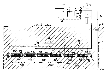
[0027] In the attached drawings, like reference numerals designate
corresponding
elements throughout. Reference is first made to Figs. 1-5A to describe an
embodiment of a heat
exchange system 20 of the invention. In one embodiment, the heat exchange
system 20 includes
a heat pump assembly 22 for controlling an indoor fluid's temperature having a
heat exchanger
24 with a heat exchange fluid 26 circulatable therein (Fig. 4). Preferably,
the heat exchange
system 20 includes one or more elongate pipe bodies 28, each pipe body 28
defining one or more
conduits 30 therein in which one or more fluids 32 are receivable (Figs. 2,
3B, 5A). Each pipe
body 28 also includes an exterior surface 34 which is adapted for engagement
with ground
material 36. In one embodiment, the heat exchange system 20 preferably also
includes one or
more ground loop circuits 38 in fluid communication with one or more pumps 40
(Fig. 4), for
circulating a heat transfer medium 42 through each ground loop circuit 38. As
can be seen in
4
CA 02697436 2010-03-22
Fig. 4, each ground loop circuit 38 preferably includes one or more end
portions 44 positioned
proximal to the heat exchanger 24 for heat exchange between the heat transfer
medium in the end
portion 44 and the heat exchange fluid in the heat exchanger 24, as well as
one or more pipe
portions 46 which are at least partially engaged with the pipe bodies 28
respectively, as will be
described. It is preferred that each ground loop circuit 38 also includes one
or more connecting
portions 48 connecting the pipe portion 46 with the end portion 44.
Preferably, each pipe portion
46 is at least partially located proximal to the conduit 30 for heat exchange
between the fluid in
the conduit and the heat exchange medium in the pipe portion 46, as will also
be described. In
addition, and as shown in Fig. 5A, the pipe portion 46 is at least partially
located proximal to the
exterior surface 34 for heat exchange between the ground material and the heat
exchange
medium in the pipe portion 46.
[0028] In one embodiment, each connecting portion 48 preferably is at least
partially
engaged with the ground material 36 for heat exchange between the ground
material and the heat
exchange medium in the connecting portion 48.
[0029] As shown in Figs. 3B and 5A, the invention includes a pipe assembly 49,
which
preferably includes the pipe body 28 and the pipe portion 46. As can be seen,
for example, in
Fig. 5A, the pipe portion 46 preferably is at least partially engaged with the
pipe body 28 and at
least partially located proximal to the conduit 30 for heat exchange between
the fluid 32 in the
conduit 30 and the heat exchange medium 42 in the pipe portion 46. Preferably,
the pipe portion
46 also is at least partially located proximal to the exterior surface 34 for
heat exchange between
the heat exchange medium 42 in the pipe portion 46 and the ground material 36.
[0030] As illustrated in Figs. 1 and 4, the heat exchange system 20 preferably
includes
the conventional heat pump assembly 22, adapted for controlling the
temperature of an indoor
fluid 23. For instance, the indoor fluid may be air inside a building 21
(e.g., a residence, or a
commercial building). As is well known in the art, in this situation, the heat
exchange fluid 26 is
used (generally, with heating or cooling elements (not shown)) to heat or cool
the air inside the
building. For illustrative purposes, the air inside the building 21 is
designated 23 in Fig. 1. As is
known, a heat pump may distribute the heat by means of a hydronic (hot water)
system, e.g.,
through baseboard radiators or an in-floor hydronic heating system. The system
may also be
CA 02697436 2010-03-22
used to heat domestic hot water using a desuperheater installed in the heat
pump (i.e., the
desuperheater takes the hot water after it leaves the compressor in the heat
pump). Excess hot
water is available in the heat pump cooling mode and is also available in the
heating mode
during mild weather when the heat pump is above the balance point and is not
working to full
capacity. Because the operation of the heat pump assembly 22 in connection
with heating and/or
cooling the indoor fluid is generally conventional in regard to its heating or
cooling of the indoor
fluid, it is not necessary to describe such operation in detail. It will be
understood that although
reference is made to only one heat pump assembly, the invention herein may be
used with a
number of heat pump assemblies, e.g., such as multiple heat pumps used in a
large building.
[0031] The conduit in the pipe body preferably is for channelling waste water,
i.e., the
pipe body preferably is a sewer pipe. The fluid in the conduit is waste water,
which may include
in fact various liquids and solids. For instance, the sewer pipe may be part
of a sanitary sewer or
a storm sewer system. As with relatively shallow ground material, the waste
water typically is
relatively warm in winter and relatively cool in summer (i.e., compared to
ambient air), and the
temperature differences are exploited in the invention. In summary, depending
on (i) the
temperatures of the ground material and the fluid in the conduit and (ii) the
results intended to be
achieved via controlling the indoor fluid's temperature, heat may be
transferred to the heat
exchange fluid in the heat exchanger from the heat exchange medium in the end
portion (i.e., the
ground material and the fluid may be used as heat sources), or alternatively,
heat may be
exchanged from the heat exchange fluid in the heat exchanger to the heat
exchange medium in
the end portion (i.e., the ground material and the fluid may be used as heat
sinks). It will be
appreciated by those skilled in the art that the pip body is not necessarily a
sewer pipe, and the
fluid in the conduit may be any suitable fluid (i.e., a fluid which is
relatively warm in winter and
relatively cool in summer).
[0032] For example, in winter, the ground material to which the pipe portion
is proximal
is relatively warm, as is the fluid in the conduit. Also, the indoor fluid
(e.g., air) typically is
required to be warmed from time to time by conventional heating means,
supplemented by the
heat pump. In this situation, heat is transferred to the heat transfer medium
in the pipe portion
(i.e., circulated through the loop circuit, including the pipe portion): (a)
from the fluid in the
conduit; and (b) from the ground material. However, when the warmed heat
transfer medium is
6
CA 02697436 2010-03-22
circulated through the end portion, such heat transfer medium is brought into
proximity to the
heat transfer fluid, which is circulating through the heat exchanger in the
heat pump (Fig. 4). In
this situation, heat is transferred from the (relatively warmer) heat transfer
medium in the end
portion to the (relatively cooler) heat transfer fluid in the heat exchanger,
thereby lowering (or
eliminating, as the case may be) the extent to which other energy inputs to
the conventional
HVAC unit are required in order to achieve the desired increase in the indoor
space's
temperature.
[0033] When the indoor fluid is to be cooled (e.g., in summer), the situation
is reversed.
Heat is transferred from the (relatively warmer) heat transfer fluid in the
heat exchanger to the
(relatively cooler) heat transfer medium as it is circulated through the end
portion of the ground
loop circuit. In this situation, heat is transferred from the heat transfer
medium: (a) to the
ground material, which is cooler than the heat transfer medium; and (b) to the
fluid in the
conduit, which is also cooler than the heat transfer medium.
[0034] It will be appreciated by those skilled in the art that the heat
exchange medium is
circulated through the ground loop circuit by one or more pumps 40 (Fig. 4).
[0035] Depending on the circumstances, it may be advantageous to include one
or more
supplemental loop circuits 50, to provide additional heating or cooling, as
the case may be.
Accordingly, in one embodiment, the heat exchange system 20 preferably also
includes one or
more supplemental loop circuits 50 in which a supplemental heat exchange
medium 52 is
circulatable, for heat exchange between the supplemental heat exchange medium
and the heat
exchange fluid in the heat exchanger. As can be seen in Fig. 4, a pump 54
preferably causes the
supplemental heat exchange medium to circulate through the supplemental loop
circuit 50. It
will be appreciated by those skilled in the art that the supplemental loop
circuit 50 may be any
one or more of a variety of loop circuits, intended to provide an additional
transfer of heat
between the heat exchange fluid and the supplemental heat exchange medium, to
supplement the
heat exchange effects of the heat exchange medium in the ground loop circuit
38. For example,
in claim 1, the supplemental loop circuit 50 preferably includes a down-hole
segment 56, as is
known. Those skilled in the art would be aware of various other configurations
(e.g., instead of
the vertical loop 56, the supplemental loop circuit 50 may be one or more
substantially horizontal
7
CA 02697436 2010-03-22
loops) which may be used to provide additional heat exchange with the ground
material.
Alternatively, the supplemental loop circuit 50 may utilize another heat
source, e.g., the
supplemental loop circuit 50 may be a solar thermal system. It will be
understood that the
supplemental loop circuit 50 is shown in the drawings as a vertical loop
system only for
convenience.
[0036] The pipe body 28 preferably is made of any suitable material. In one
embodiment, it is preferred that the pipe body 28 includes reinforced
concrete. As can be seen in
Fig. 5, the pipe portion 46 preferably includes an embedded part 58 which is
positioned in the
pipe body 28. Preferably, the pipe body 28 includes one or more internal wall
portions 60
positioned between the embedded part 58 and the conduit 30, the internal wall
portion 60 being
adapted for thermal conductivity therethrough. In addition, the pipe body
preferably includes
one or more external wall portions 62 including the exterior surface 34 and
positioned between
the embedded part 58 and the ground material 36. The external wall portion 62
preferably is
adapted for thermal conductivity therethrough.
[0037] The ground loop circuit 38 preferably includes tubing made of any
suitable
material(s), and suitable fastening means 63 as may be required to connect
parts of the ground
loop circuit together. As those skilled in the art would be aware of such
suitable fastening
means, further description thereof is unnecessary.
[0038] The end portion(s) 44 and the pipe portions 46 may be, for example,
made of
high-density polyethylene (HDPE) tubing. The inner diameter of tubing is
determined by a
number of factors. It has been found that HDPE tubing with an inner diameter
of about 19.05
mm. (3/4 inch) and an outer diameter of about 25.4 mm. (1 inch) is suitable,
e.g., where the wall
thickness is about 76.2 mm. (3 inches). (Those skilled in the art will
appreciate that, in a larger
pipe body with a thicker wall, larger tubing may be preferred.) The connecting
portion 48
preferably is at least partially made of cross-linked polyethylene ("PEX")
tubing, or it may be
HDPE tubing.
[0039] The heat exchange medium preferably is any suitable liquid or mixture
of liquids,
as would be known to those skilled in the art. For example, a mixture of water
and antifreeze
(e.g., propylene glycol, denatured alcohol, or methanol) has been found to be
suitable. Any
8
CA 02697436 2010-03-22
suitable mixture may be used. For instance, the antifreeze/water mixture may
be between 30%
and 50% (i.e., 30% by weight antifreeze to 50% by weight antifreeze). (As is
known, the mixture
with higher antifreeze content has less heat storage capacity.) The
supplemental heat exchange
medium also preferably is any suitable liquid(s), e.g., a mixture of water and
antifreeze.
[0040] Similarly, the heat exchange fluid preferably is any suitable
refrigerant (e.g., for
use in a vapor-compression cycle), as is known in the art.
[0041] As noted above, the pipe body 28 preferably is made of reinforced
concrete. As
can be seen in Figs. 3B and 5A, the pipe body 28 preferably includes a rebar
cage 64 which is
positioned generally inside the pipe body 28. The rebar cage 64 preferably is
made of any
suitable rebar material, as is known in the art. In one embodiment, the
embedded part 58 of the
pipe portion 46 preferably is attached to the rebar cage 64.
[0042] It is also preferred that the embedded part 58 of the pipe portion 46
is positioned
substantially in a wall 66 of the pipe body 28. For example, as shown in Fig.
5A, the embedded
part 58 preferably is sized and positioned so that the embedded part 58 is
substantially
equidistant from the exterior surface 34 and the conduit 30. For example, the
thickness
(designated "T", in Fig. 5A) of the wall 66 may be about 76.2 mm. (3 inches).
Where the
embedded part has an outer diameter of about 25.4 mm. (1 inch), therefore, the
internal wall
portion 60 and the external wall portion 62 preferably are each about 25.4 mm.
(1 inch) thick. It
is preferred that the embedded part 58 be positioned substantially in the wall
66 in order to
provide the pipe assembly 49 with somewhat improved structural strength. For
instance, if the
embedded part were only partly embedded and positioned for direct engagement
with the ground
material and/or the fluid in the conduit, the pipe assembly in which such
partly embedded tubing
is positioned would tend to have less structural strength overall. Because
concrete typically has
relatively good thermal conductivity (e.g., typically between about 1.7 to
about 2.0 Watts per
Kelvin per meter), it is thought that the improved structural strength
resulting from embedding
the embedded part in the wall is, on balance, advantageous, notwithstanding
that the heat transfer
between the ground material and the heat exchange medium is via the external
wall portion 62,
and the heat transfer between the fluid in the conduit and the heat exchange
medium is via the
internal wall portion 60.
9
CA 02697436 2010-03-22
[0043] It appears that the density of the concrete of the pipe body affects
the thermal
conductivity thereof with a higher density tending to result in a
correspondingly higher thermal
conductivity.
[0044] As can be seen, for example, in Fig. 5A, the pipe body 28 preferably
has a
generally conventional form in which the wall 66 is included in a
substantially cylindrical main
portion 68 of the pipe body 28 which is integrally formed with a flange
portion 70. The main
(cylindrical) portion 68 includes an end part 71 (Fig. 5A). As is well known
in the art, the flange
portion 70 is adapted to receive the end part of the main portion of a first
adjacent pipe body (not
shown in Fig. 5A). Similarly, the end part 71 is adapted to be received in the
flange portion of a
second adjacent pipe body (not shown in Fig. 5A), preferably with a
conventional gasket (not
shown) thereon.
[0045] It will be appreciated by those skilled in the art that the materials
used in the pipe
body 28, and the positioning of the pipe portion 46 relative to the pipe body
28, preferably are
selected according to various factors, including cost, structural strength,
and thermal
conductivity. For example, instead of reinforced concrete, the pipe body may
be made of any
suitable plastic material. However, and as noted above, a number of factors
should be
considered, e.g., cost; thermal conductivity; structural strength.
[0046] As can be seen in Fig. 2, the embedded part 58 of the pipe portion 46
preferably is
positioned in the pipe wall in the main portion 68 to describe a generally
helical path. In Figs.
3A and 3B, the embedded part 58 is shown positioned around the conduit for
illustrative
purposes. Also, only a part (identified as "M" in Fig. 3B) of the embedded
part 58 is shown as a
cross-section in Fig. 3B, for illustrative clarity.
[0047] In use, the heat exchange medium is pumped through an outflow part 72
of the
connecting portion 48 to which pipe portions 46 are connected. In Fig. 4, the
pipe portions
shown are designated 46A-46F for convenience. Each pipe portion 46 includes an
inlet part 74
and an outlet part 76 connected to the embedded part 58 thereof. It will be
appreciated by those
skilled in the art that various arrangements of the pipe portions 46 relative
to each other and to
the connecting portion 48 are possible. As can be seen in Fig. 4, for example,
the outlet part 76A
CA 02697436 2010-03-22
is connected to an inlet part 74B, and the outlet part 76B is connected to a
return part 78 of the
connecting portion 48.
[0048] As can be seen in Fig. 2, the heat transfer medium is pumped from the
end portion
44 (Fig. 4) through the outflow part 72 of the connecting portion 48 (as
indicated by arrow "A"
in Fig. 2) to the inlet part 74 of the pipe portion 46 (as indicated by arrow
"B"). For clarity, the
pipe portions in Fig. 2 are designated 46X - 46Z. (As described below, it is
not necessary that
certain of the pipe portions are connected in series, e.g., pipe portions 46X
and 46Y. Fig. 2
includes the pipe portions 46X and 46Y connected in series for clarity of
illustration.) The heat
transfer medium flows through the embedded part 58X of the pipe portion 46X in
the direction
generally indicated by arrow "C" to the outlet part 76X of the pipe portion
46X. The outlet part
76X is connected to the inlet part 74Y (i.e., the pipe portions 46X, 46Y are
connected in series),
and the heat transfer medium flows through the outlet part 76X and into the
inlet part 74Y, as
indicated by arrows "D" and "E" respectively.
[0049] The pipe portion 46Z is connected in parallel with the pipe portions
46X, 46Y
relative to the connecting portion 48. The heat transfer medium exists the
pipe portion 46Z via
the outlet part 76Z (as indicated by arrow "F") to move the return part 78 of
the connecting
portion 48, so that the heat transfer medium from the pipe portion 46Z is then
returned to the end
portion 44, for heat transfer with the heat transfer fluid in the heat
exchanger 24 (Fig. 4).
Movement of the heat transfer medium through the return part 78 is in the
direction indicated by
arrow "G" in Fig. 2.
[0050] As can be seen in Fig. 4, the heat exchange system 20 preferably
includes a
number of pipe bodies 28A-28F connected end-to-end for substantial alignment
of the conduits
30A-30F therein, each pipe body being connected to at least an adjacent one of
the pipe bodies.
The heat exchange system 20 preferably also includes a number of pipe portions
46A-46F, each
of the pipe portions being at least partially engaged with one of the pipe
bodies respectively. The
pipe portions are connected to form a number of groups 80A-80C. In particular,
each group 80
includes at least a first selected one of the pipe portions engaged with the
first selected one of the
pipe bodies connected in series to at least a second selected one of the pipe
portions engaged
11
CA 02697436 2010-03-22
with a second selected one of the pipe bodies adjacent thereto. Each group 80
of pipe portions
46 is respectively connected to the connecting portion 48 in parallel.
[0051] As an example, in Fig. 4, the pipe portions 46A-46F are, for
illustrative purposes,
shown as being arranged to form three groups 80A-80C. The pipe portion 46A is
connected in
series to the pipe portion 46B, to form the group 80A. The group 80A is
connected to the
connecting portion 48 in parallel. Specifically, the group 80A is connected to
the outflow part 72
via the inlet part 74A, and the group 80A is also connected to the return part
78 of the connecting
portion 48 via the outlet part 76B. In the group 80A, the first selected one
of the pipe portions is
the pipe portion 46A, and it is engaged with the pipe body 28A. The second
selected one of the
pipe portions is 46B, and it is engaged with the second selected one of the
pipe bodies, i.e., the
pipe body 28B.
[0052] The purpose of connecting pipe portions in series, to form groups, is
to improve
the efficiency of heat transfer between the heat transfer medium in the
embedded part and the
ground material, and between such heat transfer medium and the fluid in the
conduit. In the
arrangement illustrated in Fig. 4, because the pipe portions are connected in
series (i.e., in series
of two pipe portions each) the heat exchange medium is allowed the benefit of
heat exchange to
a greater extent than would be the case if, for example, each pipe portion
were connected to the
connecting portion in parallel. It will be understood that any number of pipe
portions 46 may be
connected in series to define a group.
[0053] As described above, for the heat transfer medium flowing through the
embedded
part 58 in each pipe portion 46, the heat source (or heat sink, as the case
may be) is both the
ground material 36 and the fluid 32 flowing through the conduit 30. (For the
purpose hereof, the
ground material 36 and the fluid 32 are collectively referred to as the "Heat
Source", regardless
of whether used as a heat source or a heat sink.) For example, referring to
Fig. 4, when the heat
transfer medium flows through embedded part 58A in the pipe portion 46A, heat
is transferred
between the Heat Source and the heat transfer medium in the embedded part 58A
if a
temperature difference (AT) exists therebetween. In most cases, there is a AT
between the heat
transfer medium in the embedded part 58A and the Heat Source, and as a result,
the temperature
12
CA 02697436 2010-03-22
of the heat transfer medium rises as the heat transfer medium flows through
the embedded part
58A.
[0054] It can be seen, therefore, that connection the pipe portions in series
(e.g., the pipe
portions 46A and 46B as shown in Fig. 4) is beneficial, because this results
in the heat transfer
medium being brought to a higher temperature (or a lower temperature, as the
case may be) than
would be the case if the heat transfer medium were passed through only one
pipe portion before
the heat transfer medium is returned to the connecting portion 48, to be moved
ultimately to the
end portion 44. The warmed (or cooled) heat transfer medium from the first
pipe portion (e.g.
46A) is warmed (or cooled) further when passed through the next pipe portion
(e.g. 46B) to
which the first pipe portion is connected in series.
[0055] However, those skilled in the art will appreciate that, at a certain
point, the
advantage gained by connecting the pipe portions in series disappears. This
happen when the AT
between the temperature of the heat transfer medium and the Heat Source
disappears, i.e., when
the AT approaches zero. At that point, the heat transfer medium should be
returned to the
connecting portion 48 via the outlet part (e.g., 76B, in Fig. 4) because no
further benefit can be
obtained, i.e., by directing the warmed (or cooled) heat transfer medium
through another pipe
portion in series. Those skilled in the art will appreciate that the optimum
arrangement of
connections for the pipe portions vary according to a number of factors
including, in particular,
local conditions, e.g., the temperatures of the ground and the fluid. It
appears that one optimum
arrangement is that shown in Fig. 4, i.e., only two pipe portions are
connected in series to define
a group, and the groups are connected to the connecting portion in parallel.
[0056] It will be understood that the pipe assemblies 49 are installed so that
the conduits
30 defined therein are positioned at an appropriate grade relative to the
horizontal. Such grade
preferably is in accordance with the grade at which a prior art pipe is
installed, as is well known
in the art. It will be understood that the pipe assemblies 49 illustrated in
Fig. 4 are positioned at
an appropriate grade so that the end thereof identified as "H1" is at a higher
elevation than the
end thereof identified as "H2", i.e., the fluid 32 flows through the conduits
30 in the direction
indicated by arrow "J" in Fig. 4.
13
CA 02697436 2010-03-22
[0057] It can be seen, in Figs. 2 and Fig. 4, that the heat transfer medium
flows through
the pipe portions 46 as illustrated generally from right to left, i.e., in the
direction indicated by
arrow "K" in Fig. 4. Where it is desired to transfer heat from the fluid 32 in
the conduits 30 to
the heat transfer medium, this arrangement provides an advantage because the
fluid moving
through the conduits is cooled as it moves in the direction indicated by arrow
"J" in Fig. 4. As
the arrangement is presented in Fig. 4, the fluid (not shown in Fig. 4) is
warmer on the left than it
is on the right. However, the heat transfer medium generally moves through
each pipe portion
from right to left, as illustrated in Fig. 4. This means that the heat
transfer medium is moved
toward warmer fluid, for heat exchange therewith, as the heat transfer medium
is moved through
the pipe portions connected in series, thereby resulting in more efficient
heat transfer thereto.
[0058] Accordingly, it is believed that the arrangement illustrated in Fig. 4
(i.e., with the
pipe portions of two adjacent pipe assemblies connected in series, to define a
single group which
is connected to the connecting portion 48 in parallel) generally provides
improved performance.
[0059] Preferably, the connecting portion 28 includes one or more manifolds 82
for
receiving the heat exchange medium from each group 80 from pipe portions 46
respectively at
substantially the same pressure, to permit the heat exchange medium to flow
into the manifold
from the groups at substantially equal rates of flow.
[0060] An alternative heat exchange system 120 of the invention is disclosed
in Fig. 6.
The heat exchange system 120 preferably includes a number of pipe bodies 128
connected end-
to-end for substantial alignment of the conduits therein, each pipe body being
connected to at
least an adjacent one of the pipe bodies. The heat exchange system 120
preferably also includes
a number of pipe portions 146. Each pipe portion 146 is at least partially
engaged with one of
the pipe bodies 128 respectively. (It will be understood that the pipe
portions 146 preferably are
positioned in the pipe bodies 128 in helical paths, or in any other suitable
paths. The pipe
portions 146 are not shown in helical paths in Fig. 6 to simplify the
drawing.) Also, each pipe
portion 146 is connected to one or more connection portions 128 in parallel.
[0061] As can be seen in Fig. 6, the system 120 includes three connecting
portions 148A,
148B, and 148C. The connecting portions 148A-148C are respectively connected
to pipe
portions 146A-146C, which are engaged with pipe bodies 128A-128C.
14
CA 02697436 2010-03-22
[0062] Another embodiment of the heat exchange system 220 of the invention is
disclosed in Fig. 7. The heat exchange system 220 preferably includes a number
of pipe bodies
228 connected end-to-end for substantial alignment of the conduits therein,
each pipe body being
connected to at least an adjacent one of the pipe bodies. The system also
includes a number of
pipe portions 246, each of the pipe portions 246 being at least partially
engaged with one of the
pipe bodies 228 respectively. (It will be understood that the pipe portions
246 preferably are
positioned in the pipe bodies 228 in helical paths, or in any other suitable
paths. The pipe
portions 246 are not shown in helical paths in Fig. 6 to simplify the
drawing.) Each pipe portion
246 is connected in series to the pipe portion engaged with the adjacent pipe
bodies.
[0063] As can be seen in Fig. 7, the heat exchange system 220 includes one
connecting
portion 248, and each of the pipe portions 246A-246C is connected in series.
The pipe portion
246A is connected in series with pipe portion 246B, for example.
[0064] An alternative embodiment of the pipe assembly 349 of the invention is
shown in
Fig. 5B. Preferably, the pipe body 328 includes concrete, i.e., the pipe body
328 preferably does
not include rebar. As can be seen in Fig. 5B, the embedded part 358 of the
pipe portion 346
preferably is positioned in the wall 366 substantially equidistant from the
exterior surface 334
and the conduit 330.
[0065] Another embodiment of the heat exchange system 420 of the invention is
disclosed in Fig. 8A. Preferably, the heat exchange system includes a three-
way valve 484
which provides a connection as required between the ground loop circuit 438
and the
supplemental loop circuit 450. As shown in Fig. 8A, the three-way valve 484
may, for instance,
be positioned at an outlet part 486, to connect the outlet part 486 with an
outflow part 472 of the
ground loop circuit 438.
[0066] On occasion, the flow of the heat transfer medium through the outflow
part 472 is
impeded by frost which can build up inside the outflow part 472. Such frost
build-up typically
takes place in a region at or close to the ground surface, generally
identified for illustrative
purposes as 488 in Fig. 8A. The heat exchange system 420 preferably includes a
temperature
sensor 490 which senses temperature in the relevant region 488 of the outflow
part 472. If the
temperature sensor determines that the temperature in the region 488 of the
outflow part 472 is
CA 02697436 2010-03-22
sufficiently below freezing, the sensor 490 generates a signal which is used
to activate the three-
way valve 484, to cause the outlet part 486 to be connected outflow part 472.
A variable speed
pump 487 is also activated by the signal, drawing relatively warmer heat
transfer medium from
the outlet part 486 into the outflow part 472, resulting in the melting and
removal of the frost
build-up.
[0067] Another embodiment of the heat exchange system 520 is shown in Fig. 9.
The
heat exchange system 520 is generally similar to the heat exchange system 20
shown in Fig. 4,
except that the ground loop circuit 538 and the supplemental loop circuit 550
are interconnected.
As can be seen in Fig. 9, heat transfer medium exiting the supplemental loop
circuit 550 via the
outlet part 586 passes through the pump 591 which causes the heat transfer
medium to flow into
the ground loop circuit 538 via the outflow part 572. The heat transfer medium
flows from the
connecting portion 548 to the end portion 544, and through the pump 592. The
pump 592 directs
the heat transfer medium to the supplemental loop circuit 550 via the inlet
part 594 thereof.
[0068] The invention also includes a method 601 which begins with a first step
603 of
providing a mold for forming one or more pipe bodies (Fig. 10). Next, the
rebar cage 64 is
positioned in the mold (step 605). At least a part of the pipe portion is
secured to the rebar cage
(step 607). Next, concrete is introduced into the mold to substantially embed
the rebar cage and
the part of the pipe portion attached to the rebar cage in the concrete (step
609). The concrete is
then cured to form the pipe body (step 611). Finally, the mold is removed
(step 613).
[0069] It will be appreciated by those skilled in the art that the invention
can take many
forms, and that such forms are within the scope of the invention as described
above. The
foregoing descriptions are exemplary, and their scope should not be limited to
the embodiments
referred to therein.
16