Language selection

Search

Patent 2697603 Summary

Third-party information liability

Some of the information on this Web page has been provided by external sources. The Government of Canada is not responsible for the accuracy, reliability or currency of the information supplied by external sources. Users wishing to rely upon this information should consult directly with the source of the information. Content provided by external sources is not subject to official languages, privacy and accessibility requirements.

Claims and Abstract availability

Any discrepancies in the text and image of the Claims and Abstract are due to differing posting times. Text of the Claims and Abstract are posted:

  • At the time the application is open to public inspection;
  • At the time of issue of the patent (grant).
(12) Patent: (11) CA 2697603
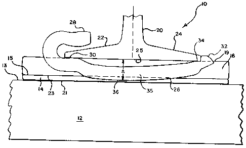
(54) English Title: RAIL ANCHOR
(54) French Title: ANTICHEMINANT
Status: Granted and Issued
Bibliographic Data
(51) International Patent Classification (IPC):
  • E01B 13/02 (2006.01)
(72) Inventors :
  • HENDERSON, JIM (United States of America)
  • BOSSHAMMER, ED (United States of America)
  • WALSH, CASEY (United States of America)
(73) Owners :
  • PROGRESS RAIL SERVICES CORPORATION
(71) Applicants :
  • PROGRESS RAIL SERVICES CORPORATION (United States of America)
(74) Agent: SMART & BIGGAR LP
(74) Associate agent:
(45) Issued: 2013-04-02
(22) Filed Date: 2010-03-23
(41) Open to Public Inspection: 2011-01-10
Examination requested: 2010-03-23
Availability of licence: N/A
Dedicated to the Public: N/A
(25) Language of filing: English

Patent Cooperation Treaty (PCT): No

(30) Application Priority Data:
Application No. Country/Territory Date
12/459,870 (United States of America) 2009-07-10

Abstracts

English Abstract

A rail anchor and a rail anchor assembly are provided for use with a concrete railroad tie. An elastomeric plate is placed on a top surface of the railroad tie. A rigid plate is placed on top of the elastomeric plate. The rail anchor is placed adjacent the elastomeric plate and the rigid plate. The rail anchor has a first end with a receiving opening and a second end with a receiving indentation to receive edges of the flanges of the railroad rail. The rail anchor has a centre portion joining the two ends. The outer portion of the rail anchor extends downwardly an amount less than the thickness of the elastomeric plate and the rigid plate to avoid contact with the concrete railroad tie.


French Abstract

Un anticheminant et un ensemble anticheminant destinés à être utilisés avec une traverse de chemin de fer en béton. Une plaque élastomère est mise sur une surface supérieure de la traverse de chemin de fer. Une plaque rigide est mise sur le dessus de la plaque élastomère. L'anticheminant est placé de façon adjacente à la plaque élastomère et à la plaque rigide. L'anticheminant possède une première extrémité munie d'une ouverture de réception et d'une seconde extrémité munie d'une indentation de réception pour recevoir les bords des patins du rail de la voie ferrée. L'anticheminant possède une partie centrale qui relie les deux extrémités. La partie extérieure de l'anticheminant s'étend vers le bas d'une distance inférieure à l'épaisseur de la plaque élastomère et de la plaque rigide pour éviter le contact avec la traverse de chemin de fer en béton.

Claims

Note: Claims are shown in the official language in which they were submitted.

CLAIMS
What is claimed is:
1. A rail anchor assembly comprising
a concrete railroad tie having a generally rectangular generally flat top
surface,
an elastomeric plate placed on the top surface of the railroad tie, the
elastomeric plate having a
flat bottom surface and a flat top surface and two parallel longitudinal
edges,
at least one generally rectangular rigid steel plate placed on the top surface
of the elastomeric
plate, the rigid steel plate having a flat top surface and a flat bottom
surface and two parallel
longitudinal edges,
a railroad rail having a first flange and a second flange placed on the top
surface of the rigid steel
plate,
and a one piece rail anchor, the one piece rail anchor comprising a first end
bent back to form a
receiving opening, a second end having a receiving indentation, and a center
portion connecting
the first and second ends,
the first end receiving opening receiving an edge portion of the first flange
of the railroad rail,
the second end receiving indentation receiving an edge portion of the second
flange of the
railroad rail,
the one piece rail anchor being positioned adjacent one of the longitudinal
edges of the
elastomeric plate and adjacent one of the longitudinal edges of the rigid
steel plate,
the center portion of the rail anchor arched away from a bottom surface of the
rail, and a lowest
bottom surface of the center portion extending downwardly an amount less than
a vertical extent
of the flat bottom surface of the elastomeric plate so as to avoid contact
between the rail anchor
and the concrete railroad tie.
2. The rail anchor assembly of claim 1
wherein the elastomeric plate is formed of a high density polymer.
3. The rail anchor assembly of claim 1
wherein the one piece rail anchor is formed of a high strength steel.

4. The rail anchor assembly of claim 1
wherein the one piece rail anchor has a generally rectangular cross section.
5. The rail anchor assembly of claim 1
wherein the rail anchor has a generally elongated structure and wherein a
bottom surface of the
center portion extends downwardly from the top surface of the rigid plate
supporting the railroad
rail no more than 1.0 inches (2.5 cm).
6. The rail anchor assembly of claim 1
wherein an additional rigid steel plate is provided on top of the rigid steel
plate.
7. The rail anchor assembly of claim 1
wherein the total thickness of the rigid steel plate and the elastomeric plate
is about 1.15 inches
(2.9 cm), and a bottom surface of the center portion of the rail anchor
extends about 1.5 inches
(3.8 cm) from the top surface of the rigid plate.
8. A rail anchor assembly comprising:
a concrete railroad tie having a generally flat top surface,
a generally rectangular elastomeric plate placed on the top surface of the
railroad tie, the
elastomeric plate having a flat bottom surface, a flat top surface, and two
parallel longitudinal
edges,
at least one generally rectangular rigid steel plate placed on the top surface
of the elastomeric
plate, the rigid steel plate having a flat top surface and two parallel
longitudinal edges,
a railroad rail having a first flange and a second flange placed on the top
surface of the rigid steel
plate,
and a one piece rail anchor, the one piece rail anchor comprised of an
elongated steel structure
having a first end bent to form a receiving opening and a second end having a
receiving
indentation, and a center portion connecting the first and second ends,
the first end receiving opening receiving an edge portion of the first flange
of the railroad rail,
the second end receiving indentation receiving an edge portion of a second
flange of the railroad
rail,
the one piece rail anchor being positioned adjacent one of the longitudinal
edges of the
6

elastomeric plate,
the center portion of the rail anchor arched away from a bottom surface of the
rail, and a lowest
bottom surface of the center portion extending downwardly an amount more than
a vertical
extent of the rigid steel plate but an amount less than a vertical extent of
the fiat bottom surface
of the elastomeric plate so as to avoid contact between the rail anchor and
the concrete railroad
tie.
9. The rail anchor assembly of claim 8
wherein the elastomeric plate is formed of a high density polymer.
10. The rail anchor assembly of claim 8
wherein the rail anchor has a generally rectangular cross section and wherein
a bottom surface of
the center portion extends downwardly from the top surface of the rigid plate
supporting the
railroad rail no more than 1.0 inches (2.5 cm).
7

Description

Note: Descriptions are shown in the official language in which they were submitted.


CA 02697603 2010-03-23
RAIL ANCHOR
BACKGROUND OF THE INVENTION
[0001] In the installation and operation of railroad rail and the operation
railroad engines
and freight cars on such rail, the standard rail fastener is a spike driven
into a wood tie on either
side of the rail. Such arrangement is designed to keep the lateral spacing
between rails to
maintain gage distance. Tie plates are also utilized as bearing pads against
lateral and vertical
forces.
[0002] Special problems have arisen due to the use of concrete ties in certain
railroad rail
installations. The particular problem with railroad rail mounted on concrete
ties is longitudinal
rail movement when holding is provided with resilient fasteners. Rail anchors
can be used to
restrict such longitudinal rail movement, which typically occurs during the
acceleration and
deceleration of trains or the expansion and contraction due to temperature
change. However,
abrasion from the steel rail anchor against the concrete tie sides tend to
erode and eventually
damage the concrete tie.
[0003] Accordingly, it is an object of the present invention to provide an
improved rail
anchor, particularly adapted for use with concrete ties.
SUMMARY OF THE INVENTION
[0004] The present invention provides rail anchor particularly adapted for use
in an
application where the railroad rail is installed on concrete ties. The rail
anchor is designed to
protect the concrete tie from longitudinal movement of the rail and, in turn,
contacting of the rail
anchor with the concrete tie, due to expansion and contraction of the rail due
to changing
temperatures, and the acceleration and deceleration of trains.
[0005] In one embodiment, the rail anchor is a one piece, elongated steel
structure having
a first end bent back to form a receiving opening. A second end has a
receiving indentation, and
a centre portion connects the first and second ends. One flange of a railroad
is received in the
receiving opening, and the second flange of the railroad is received in the
receiving indentation.
The bottom surface of the centre portion of the rail anchor extends downwardly
to a point less
than the top of the concrete tie. Abrasion with the concrete tie due to
contact with the rail anchor
thereby avoided.
1

CA 02697603 2010-03-23
[0006] It is also part of the present invention to provide a rail anchor
assembly which
comprises a concrete railroad tie having a generally flat top surface. An
elastomeric plate is
placed on the top surface of the railroad tie. The elastomeric plate itself
has a generally flat
bottom surface and a generally flat top surface. At least one rigid plate is
placed on top of the
elastomeric plate. A railroad rail is placed on top of the rigid plate. A one
piece rail anchor is
provided which has first end bent back to form a receiving opening and second
end having a
receiving indentation. A centre portion connects the first and second ends.
One edge of a first
flange of the railroad rail is received in the receiving indentation of the
rail anchor. The rail
anchor also includes a centre portion connecting the first and second ends.
The centre portion of
the rail anchor has a bottom surface which extends downwardly an amount less
than the
downward extent of the generally flat bottom surface of the elastomeric plate
so as to avoid
contact between the rail anchor and the concrete railroad tie.
BRIEF DESCRIPTION OF THE DRAWINGS
In the drawings,
Fig 1 is a side view of a rail anchor in accordance with an embodiment of the
present invention;
Fig 2 is a side view of a rail anchor in accordance with an embodiment of the
present invention
receiving the flanges of a railroad rail, and
Fig 4 is a side view, of a rail anchor assembly in accordance with an
embodiment of the present
invention.
DETAILED DESCRIPTION OF THE INVENTION
[0007] Referring now to Figures 1, a rail anchor 26 is usually comprised of
steel, and is a
generally elongated shape with usually a square or rectangular cross section.
Rail anchor 26
includes a first end 28 which is bent back at approximately 180 to form
receiving opening 30.
Rail anchor 26 also comprises second end 32 which is raised and which includes
receiving
indentation 34 on what can be deemed the top surface of rail anchor 26. The
top facing surface
of receiving opening 30 and the top facing surface of receiving indentation 34
define a place 38
which is horizontal.
[0008] Rail anchor 26 also includes a centre portion 35 which joins first end
28 with
second end 32. Centre portion 35 of rail anchor 26 includes a bottom surface
36 which extends
2

CA 02697603 2010-03-23
downwardly from plane38 a vertical distance A, which is typically between
0.875 inches and
1.00 inches (2.2 and 2.5 cm).
[0009] Referring now to Fig. 2, rail anchor 26 described above in Fig 1 is
shown
receiving railroad rail 20. Railroad rail 20 is seen to include a first flange
22 which extends into
receiving opening 30 and is supported on the top facing surface of receiving
opening 30.
Railroad rail 20 is also seen to include a second flange 24 which extends into
receiving
indentation 34 and is supported on the top facing surface of receiving
indentation 34. Railroad
rail 20 is further seen to include a generally flat bottom surface 25. Bottom
surface 25 is seen to
extend laterally between the top facing surface of receiving opening 30 and
the top facing
surface of receiving indentation 34. It is also seen that bottom surface 25 of
railroad rail 20
extends along plane 38 described above.
[0010] Referring now to Fig. 3 of the drawings, railroad rail 20 and rail
anchor 26 as
described above are present as parts of rail anchor assembly 10. Rail anchor
assembly 10 also
includes concrete railroad tie 12. Concrete railroad tie 12 includes a
generally flat top surface
13. A generally rectangular elastomeric plate 14 is placed on top surface 13
of railroad tie 12.
Elastomeric plate 14 is seen to include a generally flat top surface 15 and a
generally flat bottom
surface 21 which faces and is supported on top surface 13 of concrete railroad
tie 12.
[0011] Rigid plate 18 is provided and is placed on top of elastomeric plate
14. Rigid
plate 18 is a generally rectangular structure, usually comprised of steel, and
includes a generally
flat bottom surface 23 which faces and is supported on top surface 15 of
elastomeric plate 14. A
second rigid plate of steel can be utilized, if desired.
[0012] Railroad rail 20 includes a generally flat bottom surface 25 which is
placed on top
surface 19 of rigid plate 18.
[0013] It can be seen from Fig. 3 that the lowest vertical extent of bottom
edge 36 of rail
anchor 26 extends a distance downwardly less than the bottom surface 21 of
elastomeric plate
14. Accordingly, bottom edge 36, and in fact the sides of rail anchor 26 with
concrete railroad
tie 12 is avoided.
3

CA 02697603 2010-03-23
[0014] The usual total height of elastomeric plate 14, rigid plate 18, is
about 0.875 to 1.0
inches (2.2 to 2.5cm). The distance A from plane 38 or the bottom 25 of
railroad rail 20 is less
than 1.15 inches (2.9 cm); accordingly, contact between rail anchor 26 and
concrete railroad tie
12 is avoided.
4

Representative Drawing
A single figure which represents the drawing illustrating the invention.
Administrative Status

2024-08-01:As part of the Next Generation Patents (NGP) transition, the Canadian Patents Database (CPD) now contains a more detailed Event History, which replicates the Event Log of our new back-office solution.

Please note that "Inactive:" events refers to events no longer in use in our new back-office solution.

For a clearer understanding of the status of the application/patent presented on this page, the site Disclaimer , as well as the definitions for Patent , Event History , Maintenance Fee  and Payment History  should be consulted.

Event History

Description Date
Letter Sent 2024-03-25
Common Representative Appointed 2019-10-30
Appointment of Agent Requirements Determined Compliant 2016-10-26
Inactive: Office letter 2016-10-26
Revocation of Agent Requirements Determined Compliant 2016-10-26
Letter Sent 2016-10-19
Appointment of Agent Request 2016-10-13
Revocation of Agent Request 2016-10-13
Inactive: Late MF processed 2016-06-22
Letter Sent 2016-03-23
Letter Sent 2015-08-03
Grant by Issuance 2013-04-02
Inactive: Cover page published 2013-04-01
Inactive: Final fee received 2013-01-09
Pre-grant 2013-01-09
Letter Sent 2013-01-02
Notice of Allowance is Issued 2013-01-02
Inactive: Approved for allowance (AFA) 2012-12-20
Amendment Received - Voluntary Amendment 2012-08-13
Inactive: S.30(2) Rules - Examiner requisition 2012-08-06
Application Published (Open to Public Inspection) 2011-01-10
Inactive: Cover page published 2011-01-09
Inactive: First IPC assigned 2010-06-22
Inactive: IPC assigned 2010-06-22
Inactive: Office letter 2010-05-04
Application Received - Regular National 2010-04-28
Filing Requirements Determined Compliant 2010-04-28
Letter Sent 2010-04-28
Inactive: Filing certificate - RFE (English) 2010-04-28
All Requirements for Examination Determined Compliant 2010-03-23
Request for Examination Requirements Determined Compliant 2010-03-23

Abandonment History

There is no abandonment history.

Maintenance Fee

The last payment was received on 2013-01-25

Note : If the full payment has not been received on or before the date indicated, a further fee may be required which may be one of the following

  • the reinstatement fee;
  • the late payment fee; or
  • additional fee to reverse deemed expiry.

Please refer to the CIPO Patent Fees web page to see all current fee amounts.

Owners on Record

Note: Records showing the ownership history in alphabetical order.

Current Owners on Record
PROGRESS RAIL SERVICES CORPORATION
Past Owners on Record
CASEY WALSH
ED BOSSHAMMER
JIM HENDERSON
Past Owners that do not appear in the "Owners on Record" listing will appear in other documentation within the application.
Documents

To view selected files, please enter reCAPTCHA code :


To view images, click a link in the Document Description column. To download the documents, select one or more checkboxes in the first column and then click the "Download Selected in PDF format (Zip Archive)" or the "Download Selected as Single PDF" button.

List of published and non-published patent-specific documents on the CPD .

If you have any difficulty accessing content, you can call the Client Service Centre at 1-866-997-1936 or send them an e-mail at CIPO Client Service Centre.


Document
Description 
Date
(yyyy-mm-dd) 
Number of pages   Size of Image (KB) 
Description 2010-03-23 4 167
Abstract 2010-03-23 1 18
Claims 2010-03-23 3 116
Drawings 2010-03-23 3 26
Representative drawing 2010-12-17 1 9
Cover Page 2010-12-22 1 37
Claims 2012-08-13 3 104
Cover Page 2013-03-11 1 37
Acknowledgement of Request for Examination 2010-04-28 1 177
Courtesy - Certificate of registration (related document(s)) 2010-04-28 1 101
Filing Certificate (English) 2010-04-28 1 156
Commissioner's Notice - Maintenance Fee for a Patent Not Paid 2024-05-06 1 555
Reminder of maintenance fee due 2011-11-24 1 112
Commissioner's Notice - Application Found Allowable 2013-01-02 1 163
Late Payment Acknowledgement 2016-06-22 1 167
Maintenance Fee Notice 2016-05-04 1 170
Fees 2012-03-15 1 155
Correspondence 2010-04-28 1 13
Correspondence 2010-03-24 1 31
Correspondence 2013-01-09 2 49
Correspondence 2016-10-13 3 88
Courtesy - Office Letter 2016-10-26 1 21
Courtesy - Office Letter 2016-10-26 1 24