Note: Descriptions are shown in the official language in which they were submitted.
CA 02697669 2010-03-17
WO 2009/065194 PCT/BE2008/000097
Planet carrier of the cage type
The present invention concerns a cage-type planet
carrier.
In particular, the present invention concerns a
planet carrier for an epicyclic gear system equipped with
planetary shafts which are connected fixedly to the
planetary carrier and on which planetary wheels are mounted
in a datable manner by means of planetary bearings.
More specifically, the invention concerns a cage-
type planet carrier, the planet wheels of which are placed
between two walls of the planet carrier, where these walls
support the planetary shafts on either side of the planet
wheels.
In addition, the invention concerns a planet
carrier for planetary gear systems containing gears which
have oblique or helical gear teeth.
For planetary gear transmissions upon which
extremely high demands are made and which are subjected to
extremely high loads, such as wind turbines for instance,
gears with helical toothing are usually used, since such
gears with helical teeth possess better characteristics both
for achieving the required nominal capacity and reduction of
sound and vibration.
Some kinds of such cage-type planet carriers for
epicyclic gear systems with oblique teeth are already known.
However, they still have major problems and could
still be optimised considerably.
When designing an epicyclic gear system, a
selection has to be made regarding: the helix angle of the
gear teeth and the dimensions to be used for the ring wheel
CA 02697669 2010-03-17
WO 2009/065194 PCT/BE2008/000097
2
To achieve a particular gear ratio, the ratios between
the diameters of the various gears must meet certain
requirements.
In order to be capable of withstanding larger loads,
it may be possible to extend the dimensions of the entire gear
transmission (which should be limited as far as possible, of
course, for economic and logistic reasons) or to increase the
helix angle of the gear teeth.
A problem is that not just any selection of the
parameters stated above will be compatible with a proper bearing
support.
Choosing a larger helix angle for the gear teeth will
result for instance in more stringent requirements on the
planetary bearing.
These more stringent requirements can only be met by------,
selecting a planetary bearing with certain minimum dimensions,
as a result of which minimum dimensions for the entire gear train
may be imposed.
It is therefore obvious that only a proper combination
of all possible factors may result in the creation of a gear train
that can take larger loads with relatively small dimensions, at
least in comparison with existing planetary systems.
There are a number of restrictions when selecting
planetary bearings with larger radial dimensions, as the gear
rim of the planetary wheels must have a certain thickness to avoid
negative interactions between the teeth of the planetary wheels
and the outer bearing ring of the planetary bearing, or simply
to withstand the loads or to ensure a certain minimum lifespan
for the bearing.
Along the axial direction, the gear capacity required
imposes a minimum value on the gear width, and sufficient gear
CA 02697669 2010-03-17
WO 2009/065194 PCT/BE2008/000097
3
width is also necessary in order to be capable of taking the
torques on the planetary wheels by means of a bearing, or to
achieve proper axial and radial bearing support for the planetary
wheels.
The helix angle of the gear teeth affects the
planetary bearing, since gears with helical teeth are inclined
to move away from each other axially.
The greater the helix angle of the teeth, the greater
the axial forces between the teeth.
An epicyclic gear system has this tendency for the
gears to move apart axially, both between the ring wheel and the
planetary wheels, and between the planetary wheels and the sun
wheel.
The axial force a moving planetary wheel is subjected
to in relation to the ring wheel is opposite to the axial force
exerted by the sun wheel on the said planetary wheel.
These axial forces therefore cancel each other out,
as a result of which there is no net axial force seen at the
planetary shafts and the planetary bearing, so that this does
not affect the planetary bearing.
However, since these opposing axial forces, if
helical teeth are used, are exerted at the ring wheel and sun
wheel respectively each planetary wheel is subjected to tilting
moments which have to be handled by the planetary bearing.
It is obvious that single-row bearings, i.e. bearings
with only one row of roller elements, are not suitable for dealing
with such tilting moments, as the edges of the roller elements
would be subject to extremely large stresses in such a case.
For this reason (and to restrict the dimensions),
planetary wheels are usually mounted on their planetary shaft
by means of a bearing which is capable of dealing with tilting
CA 02697669 2010-03-17
WO 2009/065194 PCT/BE2008/000097
4
moments, usually a two-row or multiple-row bearing, such as a
double-row tapered roller bearing or a double-row cylindrical
bearing.
Another important factor to consider in this
discussion about the tilt moment on the planetary wheels is the
gear width.
This is initially determined on the basis of the
required load.
It is obvious that the same gear width is capable of
transmitting more power when a larger helix angle is used. However,
a larger helix angle also means that a larger tilting moment of
the planetary wheels must be dealt with, which in turn might
demand sufficient gear width for the bearing.
In short, smaller gear widths may be possible for a
given capacity if a larger helix angle is chosen, but the decrease
in the gear width is limited by the requirement that the planetary
bearing must still be capable of handling the tilt moment at the
planetary wheels.
However, keeping the radial dimensions of the
epicyclic gear system as small as possible is sometimes preferred,
so that fewer demands are made up on the axial dimensions of the
planetary system, for instance because manufacturing ring wheels
of large dimensions is difficult and therefore very expensive,
or because transporting such a gear system is a problem.
However, for certain required radial dimensions, the
maximum achievable load exerted onto the planetary bearing is
limited to a certain level once again.
However, extending the bearing in the axial direction
by applying multiple rows of roller elements behind one another
could solve this problem.
CA 02697669 2010-03-17
WO 2009/065194 PCT/BE2008/000097
Multiple rows of roller elements are placed axially
one after the other, for instance by placing two or more planetary
bearings below a planetary wheel or by using planetary bearings
with even more rows of roller elements, for instance roller
5 bearings with four or more rows of roller elements.
A downside of these existing designs, which use
multiple planetary bearings or multiple rows of planetary
bearings to carry a planetary wheel on a planetary shaft, is that
this results in uneven load distribution between the various
planetary bearings as well as between the various rows of roller
elements, if multiple rows of bearings are used.
The problem is not so much about achieving proper load
distribution between the various planetary wheels.
As a result of their radially symmetrical positions
and the rotation of the planet carrier and the planetary wheels
between a fixed ring wheel and an often more or less floating
sun wheel, the planetary wheels are automatically subjected to
approximately the same load, as in a design with three planetary
wheels, for example.
However, it is clear that it is difficult, if not
impossible, to achieve even load distribution across multiple
rows of roller elements that are placed at a certain axial
distance from each other below a planetary wheel, whether this
involves rows of roller elements from various single-row
bearings, or rows of roller elements from one or more than one
multiple-row bearing.
This is already the case for a purely radial load on
the planetary wheels.
In addition, helical teeth generate the tilting
moment mentioned previously, as a result of which the planetary
wheels are inclined to tilt around an axis that is perpendicular
CA 02697669 2010-03-17
WO 2009/065194 PCT/BE2008/000097
6
to the axis of rotation of the planet carrier, which makes it
even more difficult to achieve an even load distribution between
the various planetary bearings or the rows of roller elements
of these planetary bearings.
After all, under the influence of this torque, the
stresses are mainly focused on the axially outermost bearings
or rows of roller elements, whereas the intermediate bearings
or rows of roller elements are less exposed to this tilting
torque.
This problem of uneven load distribution becomes
highly evident as soon as more than two rows of roller elements
are used in the planetary bearings to support each planetary
wheel, whether this involves more than two rows of roller
elements from several single-row bearings, or more than two rows
of roller elements from one or more multiple-row bearings.
After all, two rows of roller elements suffice to
handle a tilting moment, so that in such a configuration with
only two rows of roller elements the load on each row of roller
elements is determined directly.
This case is known as a statically determined system.
However, if more than two rows of roller elements,
axially placed with respect to one another, are used to support
a planetary wheel, then it will not be immediately clear to what
extent each row of roller elements is contributing to supporting
the planetary wheel.
This case is known as a statically over-determined
system.
In a lot of cases, certain rows of roller elements will
therefore be subjected to the major part of the load, whereas
other rows of roller elements will only be partially loaded or
not at all.
CA 02697669 2010-03-17
WO 2009/065194 PCT/BE2008/000097
7
Such planetary bearings with more than two rows of
roller elements are therefore usually unevenly loaded and as a
result are far from efficient.
Uneven load distribution of the bearings or the rows
of roller elements within the bearings may lead to early wear
of the bearings or of parts that are supported by these bearings.
To make things clear, we would like to point out the
fact that there are already a number of planet carrier designs
with planetary shafts, each of them equipped with more than one
planetary bearing, where even load distribution across the
various rows of roller elements of the planetary bearings is
almost achieved.
However, these planet carriers are of a totally
different type than the planet carriers which this invention is
referring to.
More specifically,,these existing planet carriers use
what is called a bogie plate, which supports the planetary shafts
in the centre (and in the centre only), and where bearings are
placed on either side of the bogie plate in order to support a
planetary wheel.
The planetary shafts are mounted loosely onto the
bogie plate using a kind of ball joint, which naturally ensures
proper load distribution.
Such planet carriers with bogies plate are intended
for special purposes, for instance in wind turbines where the
gearbox with the ring wheel has a fixed position in relation to
the wind turbine housing and extensive integration of the rotor
bearing is involved.
As a result of rotor load or play in the bearing or
other such aspects, the rotor shaft in such configurations is
subject to rather large movements with respect to the housing,
CA 02697669 2010-03-17
WO 2009/065194 PCT/BE2008/000097
8
resulting in substantial alignment errors between the gear
wheels.
To cope with these alignment errors, the planetary
shafts are mounted on the bogie plate in a moveable manner,
allowing the gear wheels to position themselves.
The present invention is typically intended for gear
systems in wind turbines, for example, where the gearbox is hung
on the rotor shaft, as a matter of speaking, and where the planet
carrier and the sun wheel are in the gear box housing, in addition
to that possibly supported by means of bearings.
The link between the gearbox and the wind turbine
housing is somewhat elastic, allowing the ring wheel, the
planetary wheels and the sun wheel to follow the movement of the
rotor shaft continuously and to remain precisely aligned (apart
from possible small deviations).
It is clear that load distribution in such a rather
rigid configuration, which the invention refers to, and where
planetary wheels are supported by more than one row of roller
elements behind one another, may be_problematic and therefore
requires a solution.
Apart from the fact that the bogie plate solution is
intended for other applications, the downside of such gear
systems is that they are very difficult to manufacture, resulting
in high cost prices.
In addition, certain gear wheel types are excluded if
bogies plate are used.
For instance, the use of helical teeth is out of the
question for a planet carrier with a bogie plate.
DE 0.054.280 has another solution, the objective of
which is to achieve even,load distribution across the various
planetary wheels.
CA 02697669 2010-03-17
WO 2009/065194 PCT/BE2008/000097
9
The attention is in this case mainly focused on the
problem that extreme distortions may occur at the planetary
shafts and the sun wheel if large gear.ratios are used.
The solution offered is not to combat the distortions
that arise, but on the contrary to allow them to occur.
As was explained above, such a solution is unsuitable
for the applications that this invention refers to, since
distortions must be restricted as much as possible, of course.
In addition the embodiment of DE 0.054.280 has many
other disadvantages.
The planetary wheels are supported by needle bearings,
separated from eachother by retainer plates, which will
inevitably result in wear.
Moreover, DE 0.054.280 only envisages a single roller
element for each planetary wheel.
The solution proposed in DE 0.054.280 is not at all
suitable for oblique teeth, given that the presence of 1 rolling
element for each planetary wheel is not sufficient to handle the
tilting moments that are present in the case where helical teeth
are used.
The objective of the present invention is to offer
solutions to one or several disadvantages, including those
mentioned previously.
For this purpose, the current invention is a planet
carrier for an epicyclic gear system, with planetary shaft which
are connected fixedly to the planet carrier, onto which planetary
wheels are mounted rotatably using planetary bearings, where the
teeth of the planetary wheels are helical or chevron teeth, with
the planet carrier being of a cage type, and in which more
specifically the planet wheels are placed between two walls of
the planet carrier, and where these walls support the planetary
CA 02697669 2010-03-17
WO 2009/065194 PCT/BE2008/000097
shafts on either side of the planetary wheels, and where,
according to the invention, at least two separate planetary
wheels are mounted on each planetary shaft, each wheel of which
being supported by at least one planetary bearing, each planetary
5 wheel being supported by a planetary bearing which is a
double-row cylindrical bearing, where the outer bearing ring of
each double-row cylindrical bearing is integrated in the said
planetary wheel.
The major advantage of such a planet carrier according
10 to the invention is that it achieves a compact design which is
capable of dealing with very high loads.
The technical problems which have to be overcome when
manufacturing a ring wheel for an epicyclic gear system, as well
as the problems which occur during its transport and therefore
the total costs for manufacturing such a gear wheel, will rise
exponentially as the ring wheel dimensions increase, which is
why it is extremely useful to be able to take greater loads with
relatively limited gear widths and gear wheel diameters, as is
the case with an epicyclic gear system according to the
invention.
Another major advantage of such a planet carrier
according to the invention is that load distribution between the
planetary bearings and/or the rows of roller elements of these
bearings is much better and more even.
In particular, the load distribution is improved
between the bearings or rows of roller elements of the bearings
which are in various planes perpendicular to the axis of rotation
and at a given axial distance from each other.
The reason for this is that the even load distribution
depends less on a highly accurate adjustment of the play in each
bearing or in each row of roller elements of the bearings.
CA 02697669 2010-03-17
WO 2009/065194 PCT/BE2008/000097
11
After all, each individual planetary wheel on a
planetary shaft of the planet carrier has some play and is
therefore able to move slightly within its own supporting bearing
or supporting bearings, allowing load distribution between the
rows of roller elements of that bearing or between the roller
elements of the various supporting bearings.
In general, if more than one planetary wheel is used
on a single shaft, better load distribution across the various
rows of roller elements of the bearings axially placed next to
each other is achieved than if the same bearings, as in the
existing planet carriers, were to support just one planetary
wheel.
For the same reason, improved load distribution is
achieved for taking the tilting moment mentioned previously
around an axis perpendicular to the axis of rotation, which
occurs when helical teeth are used for the planetary wheels, as
each planetary bearing below one of the planetary wheels - which
are placed next to each other axially - can position itself
separately to bear this tilting moment load.
Another advantage of using more than one planetary
wheel for each planetary shaft, with each planetary wheel
supported by a double-row cylindrical bearing, is that the
assembly of the planetary bearings is greatly simplified.
After all, it is possible to install the subsequent
axial planetary wheels one after the'other on the planetary
shaft.
Finally, the subsequent planetary wheel or possibly
multiple subsequent planetary wheels can be installed against
the previous planetary wheel.
In order to better explain the characteristics of the
invention, the following preferred embodiment is described by
CA 02697669 2010-03-17
WO 2009/065194 PCT/BE2008/000097
12
way of example only, without being limitative in any way, with
reference to the accompanying drawings, in which:
figure 1 represents a cross-section of a known
cage-type planet carrier, each planetary shaft having one
planetary wheel, which is supported by one double-row
cylindrical roller bearing;
figure 2 represents also a cross-section of a known
cage-type planet carrier, each planetary shaft now having one
planetary wheel, which is supported by two double-row
cylindrical roller bearing;
figure 3 provides a schematic diagram of how radial
load and tilt moment load are distributed across the various rows
of cylindrical rollers in the case of the planet carrier in
figure 2;
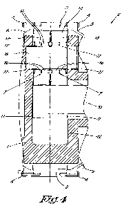
figure 4 shows a cage-type planet carrier according
to the invention, each planetary shaft being equipped with two
planetary wheels, each one supported by its own double-row
tapered roller bearing;
figures 5 and 6 show two different embodiments of a
cage-type planet carrier according to the invention; and
figure 7 shows the distribution of radial load and
tilt moment load over the various rows of cylindrical rollers
for the planet carrier of figure 4, in the same way as in figure 3.
The planet carrier 1 shown in figure 1 is a cage-type
planet carrier and part of an epicyclic gear system 2.
Furthermore, the epicyclic gear system is made up of:
a ring wheel 3, which is connected to a housing 5 by bolts 4;
planetary wheels 6, of which one only is shown in figure 1, which
are mounted rotatably on the planetary shafts 8 of the planet
carrier 1; and a sun wheel 9 mounted to an output shaft 10.
CA 02697669 2010-03-17
WO 2009/065194 PCT/BE2008/000097
13
It is known that a planet carrier 1 of an epicyclic
gear system 2 can be used to convert a slow rotation of the planet
carrier 1 into a fast rotation of the output shaft 10, through
interaction between the planetary wheels 6 on this planet
carrier 1 with the ring wheel 3 and the sun wheel 9.
In this known caged-type planet carrier 1, the planet
wheels 6 are placed between two walls 11 and 12 of the planet
carrier 1.
In addition, the walls 11 and 12 support the planetary
shafts 8 on either side of the planetary wheels 6.
As was explained in the introduction, the
possibilities for mounting the planetary bearings 7 on the
planetary shafts 6 are rather limited, since the dimensions
and/or diameters D of the planetary bearings 7 must be limited.
One reason for this is that the thickness T of the gear
rim 13 of the planetary wheels 6 must be sufficiently large to
avoid problems of interaction between the teeth 14 of the
planetary wheels 6 and the outer bearing ring 15 of the planetary
bearings 7.
Knowing this and since the inner diameter D' of the
ring wheel 3 is usually a given parameter, there will be little
room left for planetary bearings 7 with large diameters D.
To ensure a certain degree of compactness of the
bearing and to be able to cope with a sufficiently large load,
double-row bearings are therefore often used for the planetary
bearings 7, as shown in figure 1, where two rows of roller
elements 16 are placed between a pair of outer bearing rings 15
and inner bearing rings 17, which may or may not be manufactured
as a single piece.
In this case, double-row cylindrical roller
bearings 7 were used, but tapered roller bearings are often used
CA 02697669 2010-03-17
WO 2009/065194 PCT/BE2008/000097
14
for this purpose too, and the bearings 7 may even be multiple-row
bearings.
If larger loads are involved compared to the
dimensions of the planet carrier 1, another existing solution
should often be adopted for reasons previously mentioned, a
solution shown as an example in figure 2, where the planet
wheels 6 are mounted on the planetary shafts 8 using more than
one planetary bearing 7, each of which being of the multiple-row
cylindrical type.
However, this known planet carrier 1 has several
disadvantages, especially regarding load distribution over the
various rows of roller elements 16, which are placed at an axial
distance from each other, as will be demonstrated below by making
reference to figure 3.
The left part of figure 3 shows how in a planet
carrier 1, manufactured as shown in figure 2, a radial load R
on a planetary wheel 6, resulting for instance from gear teeth
forces, is transferred through the rows of roller elements 16
from the pair of double-row cylindrical roller bearings 7 to the
planetary shafts 8.
To indicate that the planetary bearings 7 with their
rows of roller elements 16 are considered as deformable elements,
as a result of radial play in the bearings 7, for instance, the
planetary bearings 7 were shown as spring elements in figure 3.
Under the influence of radial load R and the radial
play in the bearings 7, a planetary wheel 6 has a tendency to
position itself.
If the radial play in the bearings 7 is not absolutely
equal for all bearings, which is of course often the case in
practice, this will cause certain rows of roller elements 16 to
CA 02697669 2010-03-17
WO 2009/065194 PCT/BE2008/000097
be more heavily loaded than other rows 16 when a planetary wheel 6
is positioning itself.
This has been indicated in the example shown in
figure 3 by placing dots at the most heavily loaded rows 16.
5 The right part of figure 3 schematically shows a
similar phenomenon, which occurs under the influence of a tilting
moment M, resulting for example from the interaction between the
teeth of planetary wheels 6 with the sun wheel 10 and ring wheel 3
when helical teeth are used.
10 As indicated in figure 3,. the axial outer rows of
roller elements 16 are in this case subjected to larger loads
than the rows of roller elements 16 which are situated more at
the inner side.
Of course, this uneven load distribution across the
15 bearings 7 and the rows of roller elements 16 affects negatively
the lifespan of the bearings 7.
The solution to the above mentioned disadvantages is
a cage-type planet carrier 18 according to the invention, a
possible embodiment being shown in figure 4.
Typical of this planet carrier 18 according to the
invention is that each planetary shaft 8 has two separate
planetary wheels 6, each of which being supported by a planetary
bearing 7 of its own, this planetary bearing 7 being a double-row
cylindrical bearing, where the exterior bearing ring 15 of each
double-row cylindrical bearing 7 is integrated in the planetary
wheel 6 concerned.
It is important to notice that the invention refers
to epicyclic gear systems 20 where the teeth 14 of the planetary
wheels 6 are helical or chevron type (i.e. V shaped).
As has already been explained, using these helical
teeth 14 generates axial forces which result in tilting moments
CA 02697669 2010-03-17
WO 2009/065194 PCT/BE2008/000097
16
on the planetary wheels and these tilt moments must be dealt with
by the supporting bearings.
In a cage-type planet carrier according to the
invention, multiple planetary wheels 6 are provided for each
planetary shaft 8, each with its own double-row cylindrical
bearing 7, so that a greater load capacity is achieved.
Using separate planetary wheels 6 allows working with
integrated outer bearing rings 15, while also resulting in proper
load distribution across the separate double-row cylindrical
bearings 7.
In other words, in a planet carrier 18 according to
the invention all possible factors have been taken into account
in an optimal way.
Both the radial and axial dimensions are restricted
to the minimum with a maximum capacity for dealing with both
radial loads and moment loads.
A substantial part of the idea of the invention is not
to work with a single planetary wheel 6 on each planetary shaft
8, possibly supported by more than one planetary bearing 7, as
is the case with known planet carriers 1, but to `split up' this
planetary wheel 6, so to speak, so that each part, forming a
planetary wheel 6 in itself, is supported by its own planetary
bearing 7.
The advantage of this "split" is explained hereafter
by making reference to figure 7, where the load distribution
across the various rows of roller elements 16 of the planetary
bearings 7 is shown similarly to figure 3, in the left part for
radial load R and in the right part for tilt moment load M
respectively.
"Splitting" the planetary wheels actually results in
separate systems, in the shape of separate planetary wheels,
CA 02697669 2010-03-17
WO 2009/065194 PCT/BE2008/000097
17
which are all statically determined, so that the above mentioned
problem - which occurs in statically over-determined systems -
is resolved.
It is clear that both planetary wheels 6 of planet
carrier 18 according to the invention will tend to position
themselves separately under the influence of radial load R or
tilting moment M.
In the event of radial load R, for instance, part of
the radial load R is dealt with by one of the planetary bearings 7
and the rest of radial load R by the other planetary bearing 7.
Since each planetary wheel 6 is able to position
itself independently, the part of the radial load R concerned,
no matter the difference in play in the rows of roller elements
16 in the supporting bearing 7 (at least within certain
boundaries and for bearings with a maximum of two rows of roller
elements 16) will be almost evenly distributed between both rows
of roller elements 16 of the bearing 7.
So, in the aggregate, a planet carrier 18 according
to the invention will therefore achieve better distribution of
radial load R across the four rows of roller elements 16 of the
two planetary bearings 7 than known planet carriers 1, where a
single planetary wheel 6 is supported by a total of four rows
of roller elements 16 with different amounts of radial play, as
shown in figure 3.
It is clear that there is similarly better load
distribution of tilting moment M between the four rows of roller
elements 16 (resulting from independent positioning of the
planet wheels 6), since each planetary wheel 6 will position
itself and the rows of roller elements 16 and the partial load
on each planetary wheel 6 will be distributed across the two rows
of roller elements 16 of that planetary wheel 6.
CA 02697669 2010-03-17
WO 2009/065194 PCT/BE2008/000097
18
As a result, the four rows of roller elements 16 of
each planetary shaft 8 play a role in transferring tilt moment
load M, whereas in the existing example of figure 3, only the
load on the axially outermost rows of roller elements 16 is worth
mentioning.
In the embodiment of figure 4, the two rows of
rollers of a single bearing share the same inner ring, so
that the planetary wheels are made in such a way, that
assembly is possible so as e.g. shown in the figure in the
current embodiment of figure 4 a collar being used on one
side of the planetary wheel and a circlip on the other side,
which prevents axial movement of the planetary wheels.
In another embodiment, each row of rollers has its
own inner ring, meaning that the planetary wheel can be made
differently, e.g. as shown in figure 5. In this embodiment,
a collar is provided in the middle of the planetary wheel,
which is different from the embodiment shown in figure 4.
It is possible to prevent the axial movement of the planetary
wheels in this embodiment without using a circlip.
An alternative embodiment is shown in figure 6.
In this embodiment, each inner ring has only a single axial
collar instead of two, as was the case in the variant shown
in figure 5.
The embodiments described above and the
associated figures are only intended as illustrations and
are in no way intended to restrict the scope of the invention.
Another special characteristic of the embodiment
shown in figure.4 of a planet carrier 18 according to the
invention is that the outer bearing ring 15 of the double-row
cylindrical bearings is made as a single piece.
CA 02697669 2010-03-17
WO 2009/065194 PCT/BE2008/000097
19
In addition, the bearing ring 15 is integrated in
the planetary wheel 6.
This results in a planet carrier 18 which is both
efficient and very compact.
It is clear that a lot of alternatives are possible
for a planet carrier 18 according to the invention.
The most inner bearing rings 17 of the planetary
bearings 7 of each planetary axle 8 should preferably be directly
in contact with one another.
This would make assembly extremely simple. Indeed, it
only requires the inner bearing rings 17 to be pushed along the
planetary shafts 8 until they are in contact with one another.
Alternatively, the inner bearing rings 17 of the
planetary bearings 7 of each planetary shaft 8 can be in, contact
with each other using one or more spacer bushes which are placed
along the planetary shaft 8 between the inner bearing rings 17.
In this way it is once again very easy to achieve the
appropriate positioning of the bearing rings 17 on the planetary
shafts 8.
The axial location is obtained by enclosing the inner
bearing rings 17 of the planetary bearings 7 of each planetary
shaft 8 between a collar on the planetary shaft 18 on one end
and a wall 11 or 12 of the planet carrier 18 on the other end.
The inner bearing rings 17 are preferably supported
by the above mentioned wall 11 or 12 of the planet carrier 18,
against a surface that has been mechanically processed for the
purpose.
An advantage not yet mentioned regarding the use of
integrated outer bearing rings 15 is that they cannot get loose
and so cause wear, so that the lifespan of the bearings 7 is higher
CA 02697669 2010-03-17
WO 2009/065194 PCT/BE2008/000097
than in the case of individual non-integrated outer bearing
rings 15.
Furthermore, it is possible, according to the present
invention, to make local changes to the microgeometry of teeth 14
5 of the planetary wheels 6 in order to achieve improved load
transfer from the sun wheel 9 and ring wheel 3 towards planetary
wheels 6.
For instance, one could opt for modifying the
microgeometry of the planetary wheels 6 in such a way that it
10 would be almost the same for planetary wheels 6 which are situated
at the same axial distance from the walls 11 and 12 of the planet
carrier, but that it would be different for planetary wheels 6
placed axially next to each other.
In the example shown in figure 4, each planetary
15 shaft 8 is provided with two planetary wheels 6, but according
to the invention it is also possible to install more than two
planetary wheels on each planetary shaft 8, for example, with
each planetary wheel 6 being supported by at least one planetary
bearing 7.
20 The invention is in no way restricted to the
embodiment of a planet carrier 18 according to the invention,
described as an example and shown in the figures and such a planet
carrier 18 can be realised in all kinds of other ways while still
remaining within the scope of the invention.