Language selection

Search

Patent 2698068 Summary

Third-party information liability

Some of the information on this Web page has been provided by external sources. The Government of Canada is not responsible for the accuracy, reliability or currency of the information supplied by external sources. Users wishing to rely upon this information should consult directly with the source of the information. Content provided by external sources is not subject to official languages, privacy and accessibility requirements.

Claims and Abstract availability

Any discrepancies in the text and image of the Claims and Abstract are due to differing posting times. Text of the Claims and Abstract are posted:

  • At the time the application is open to public inspection;
  • At the time of issue of the patent (grant).
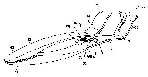
(12) Patent: (11) CA 2698068
(54) English Title: COMBINATION BREADING TONGS AND DIPPING TOOL
(54) French Title: PINCES A PANER ET OUTIL DE TREMPAGE COMBINES
Status: Granted and Issued
Bibliographic Data
(51) International Patent Classification (IPC):
  • A47G 21/10 (2006.01)
  • A47G 21/00 (2006.01)
  • A47G 21/08 (2006.01)
(72) Inventors :
  • WALDMAN, LYNN (United States of America)
  • JONES, JACLYN (United States of America)
  • LUPKES, WILLIAM (United States of America)
  • ARAIZA, THERESE (United States of America)
  • HAUSER, LAWRENCE MICHAEL (United States of America)
(73) Owners :
  • COLUMBIA INSURANCE COMPANY
(71) Applicants :
  • COLUMBIA INSURANCE COMPANY (United States of America)
(74) Agent: GOWLING WLG (CANADA) LLP
(74) Associate agent:
(45) Issued: 2013-12-10
(86) PCT Filing Date: 2008-08-25
(87) Open to Public Inspection: 2009-03-05
Examination requested: 2011-07-07
Availability of licence: N/A
Dedicated to the Public: N/A
(25) Language of filing: English

Patent Cooperation Treaty (PCT): Yes
(86) PCT Filing Number: PCT/US2008/074232
(87) International Publication Number: US2008074232
(85) National Entry: 2010-02-26

(30) Application Priority Data:
Application No. Country/Territory Date
11/848,734 (United States of America) 2007-08-31

Abstracts

English Abstract


A kitchen utensil includes a handle having a dipping utensil at one end and a
gripping surface at a second end thereof.
The dipping utensil includes a frame member defining an opening. A tong member
is engaged to the handle and is rotatable with
respect to the handle between open and closed positions. The tong includes an
actuation lever at one end and a gripping surface on
a second end, whereby the gripping surfaces of the handle and tong may
cooperate to hold an item placed therebetween.


French Abstract

L'invention porte sur un ustensile de cuisine qui comprend une poignée comportant un ustensile de trempage à une extrémité et une surface de saisie à une deuxième extrémité de celle-ci. L'ustensile de trempage comprend un élément de cadre définissant une ouverture. Un élément de pince est en prise avec la poignée et peut tourner par rapport à celle-ci entre des positions ouverte et fermée. La pince comprend un levier d'actionnement à une extrémité et une surface de saisie sur une deuxième extrémité, les surfaces de saisie de la poignée et de la pince pouvant coopérer de façon à maintenir un article placé entre celles-ci.

Claims

Note: Claims are shown in the official language in which they were submitted.

What is claimed is:
1. A kitchen utensil comprising:
a handle member, comprising a first end, forming a first gripping surface, and
a second
end;
a dipping utensil engaged to the second end of the handle member and extending
at a first
angle therefrom, the first angle being greater than zero, the dipping utensil
comprising a frame
member defining an opening;
a tong member engaged to the handle member, and rotatable with respect to the
handle
member between a first, closed position and a second, open position, the tong
member having a
first end, forming a second gripping surface, and a second end; and
an actuation lever formed on the second end of the tong member, the actuation
lever
positioned entirely between the first and second ends of the handle member and
having a length
such that it does not extend past any portion of the dipping utensil;
wherein the first gripping surface and the second gripping surface cooperate
to grasp any
item placed therebetween.
2. The kitchen utensil as set forth in claim 1, further comprising a
biasing spring engaged to
the handle member and the tong member, wherein the biasing spring biases the
tong member to
the first, closed position.
3. The kitchen utensil as set forth in claim 2, wherein the actuation lever
extends at a second
angle from the tong member, the second angle being greater than zero.
4. The kitchen utensil as set forth in claim 3, wherein the actuation lever
is integrally
formed from the tong member.
5. The kitchen utensil as set forth in claim 1, wherein the dipping utensil
is integrally
formed from the second end of the handle member.
6. The kitchen utensil as set forth in claim 1, further comprising first
and second hinge
members extending from the tong member, and third and fourth hinge members
extending from
the handle member, wherein the first and second hinge member cooperate with
the third and
fourth hinge members, respectively, to hingedly connect the tong member to the
handle
member.
6

7. The kitchen utensil as set forth in claim 6, wherein a hinge bar is
engaged to each of the
hinge members.
8. The kitchen utensil as set forth in claim 3, wherein the difference
between the first angle
and the second angle is less than 5 degrees.
9. A kitchen utensil comprising:
a handle member comprising a first end and a second end;
a first gripping surface formed on the first end of the handle member;
a dipping utensil engaged to the second end of the handle member, the dipping
utensil
formed at a first angle with respect to the handle member, the first angle
being greater than
zero;
a tong member hingedly engaged to the handle member, the tong member
comprising a
first end and a second end and rotatable with respect to the handle member
between a closed
position and an open position;
a second gripping surface formed on the first end of the tong member;
an actuation lever engaged to the second end of the tong member, the actuation
lever
positioned entirely between the first and second ends of the handle member and
having a length
such that it does not extend past any portion of the dipping utensil, the
actuation lever formed at
a second angle with respect to the tong member, the second angle being greater
than zero; and
a biasing spring engaged to the handle and the tong member, the biasing spring
biasing
the tong member to the closed position.
10. The kitchen utensil as set forth in claim 9, wherein the difference
between the first angle
and the second angle is less than 5 degrees.
11. The kitchen utensil as set forth in claim 9, wherein the difference
between the first angle
and the second angle is more than 5 degrees.
12. A kitchen utensil comprising:
a handle member comprising a first end and a second end;
a first gripping surface formed on the first end of the handle member;
a dipping utensil engaged to the second end of the handle member, the dipping
utensil
7

formed at a first angle with respect to the handle member and comprising a
frame member
defining an opening having a periphery, the first angle being greater than
zero;
a tong member hingedly engaged to the handle member, the tong member
comprising a
first end and a second end and rotatable about an axis of rotation with
respect to the handle
member between a closed position and an open position, and wherein the axis of
rotation is
parallel to a plane formed by the periphery of the opening;
a second gripping surface formed on the first end of the tong member;
an actuation lever engaged to the second end of the tong member, the actuation
lever
positioned entirely between the first and second ends of the handle member and
having a length
such that it does not extend past any portion of the dipping utensil, and
formed at a second angle
with respect to the tong member, the second angle being greater than zero; and
a biasing spring engaged to the handle and the tong member, the biasing spring
biasing
the tong member to the closed position.
13. The kitchen utensil as set forth in claim 12, wherein the difference
between the first angle
and the second angle is less than 5 degrees.
14. The kitchen utensil as set forth in any one of claims 1-11, wherein the
dipping utensil
comprises a frame member defining the opening having a periphery.
15. The kitchen utensil as set forth in any one of claims 12-14, wherein
the axis of rotation
of the tong member is parallel to a plane formed by the periphery of the
opening.
16. A utensil comprising:
a handle member comprising a first end and a second end;
a first gripping surface formed on the first end of the handle member;
a dipping utensil engaged to the second end of the handle member, the dipping
utensil
formed at a first angle with respect to the handle member, the first angle
being greater than zero;
a tong member hingedly engaged to the handle member, the tong member
comprising a
first end and a second end and rotatable with respect to the handle member
between a closed
position and an open position;
a second gripping surface formed on the first end of the tong member;
an actuation lever engaged to the second end of the tong member, the actuation
lever
8

formed at a second angle with respect to the tong member, the second angle
being greater than
zero; and
a biasing spring engaged to the handle and the tong member, the biasing spring
biasing
the tong member to the closed position,
wherein the difference between the first angle and the second angle is less
than 5 degrees.
9

Description

Note: Descriptions are shown in the official language in which they were submitted.


CA 02698068 2013-06-19
COMBINATION BREADING TONGS AND DIPPING TOOL
Background of the Invention
[0002] This invention relates to a combination tongs and dipping
tool.
Summary of the Invention
[0003] A combined tongs and dipping tool is described herein. The
details of the
invention are set forth below in connection with the detailed description of
the embodiments.
Brief Description of the Drawings
[0004] Fig. 1 is a perspective view of a first embodiment of the
present invention,
with the tong members in the closed position as described in detail below.
[0005] Fig. 2 is a first side view of the embodiment of the present
invention
depicted in Figure 1.
[0006] Fig. 3 is a second side view of the embodiment of the
present invention
depicted in Figure 1, opposite the side view depicted in Figure 2.
[0007] Fig. 4 is a perspective view of the first embodiment of the
present
invention, with the tong members in the open position as described in detail
below.
Detailed Description of the Drawings
[0008] The present invention is described herein with respect to
exemplary
kitchen utensil 10, which is shown in Fig. 1. It will be understood that other
kitchen utensils
and applications can be used in accordance with the present invention.
1

CA 02698068 2010-02-26
WO 2009/029584 PCT/US2008/074232
[0009]
In the depicted embodiment, kitchen utensil 10 comprises handle member
12, which comprises first end 14 and second end 16. First end 14 of handle
member 12 forms
first gripping surface 18, which is used in the tong function of kitchen
utensil 10 as described
in detail below.
[0010] In order
to provide kitchen utensil 10 with a gripping function, utensil 10
may further comprise tong arm 40, which comprises a first end 42 and a second
end 44. As
seen in Fig. 4, first end 42 comprises second gripping surface 46, for the
gripping purpose of
kitchen utensil 10, and second end 44 comprises an actuation lever 48.
[0011]
It will be appreciated by those in the art that while the current invention
comprises many functions, two of those functions are prominent: a holding
function and a
gripping function. Thus, the disclosed invention provides a single tool which
enables the user
to perform multiple tasks, eliminating the need for multiple tools and thereby
reducing clutter
and cost. When utilizing the holding function of utensil 10, the user may use
utensil 10 along
with a dipping receptacle (not shown). The dipping receptacle is intended to
be a bowl or
similar item, such as for use in fondues and the like. The dipping receptacle
may be made of
any type of material, and may contain a liquid of some sort therein. The
liquid may be hot or
cold, depending on the type of material used for the dipping receptacle. In
order to provide
the user the ability to dip a desired food article into a dipping receptacle,
dipping utensil 30
may be attached to second end 16 of handle member 12. In the depicted
embodiment,
dipping utensil 30 comprises a frame 32, which defines an opening 34 having a
size and
shape appropriate to hold a bite-size food item.
[0012]
As seen in the depicted embodiment, dipping utensil 30 may be integrally
formed with handle member 12. However, it is within the scope of the present
invention that
dipping tool 30 may be attached to handle member 12 by snaps, a tongue-in-
groove
2

CA 02698068 2010-02-26
WO 2009/029584 PCT/US2008/074232
arrangement, or other known means. Dipping tool 30 is depicted formed at an
angle with
respect to handle member 12.
[0013]
When utilizing the holding function of kitchen utensil 10, the user grasps
both first end 14 of handle member 12 and first end 42 of tong member 40 and
places a food
item (not shown) in opening 34, or, if suitable, attaches a food item to frame
32. The user
then lowers both dipping utensil 30 and the food item into a liquid (not
shown) that is
contained within the dipping receptacle. Because dipping utensil 30 is formed
at an angle
with respect to handle member 12, if the dipping receptacle is very narrow, or
if there is a
large distance between the surface of the liquid and the top of the dipping
receptacle, the user
may still utilize kitchen utensil 10, and dip the food item and dipping
utensil 30 into the
liquid without getting any of the liquid on the user's hand.
[0014]
By way of example, and in no way limiting, in order to cover a strawberry
with chocolate, the user may place a strawberry on dipping utensil 30, resting
the strawberry
on frame 32. The user may then submerge both the strawberry and dipping
utensil 30 into a
liquid, such as melted chocolate, that is contained in the dipping receptacle.
When the
strawberry is sufficiently coated, the user may remove the strawberry and
dipping utensil 30
from the liquid, and move the strawberry to a different location, to allow the
liquid to
solidify.
[0015]
It will be appreciated by those in the art that dipping utensil 30 may not
be
appropriate for certain types of food items or for certain types of food
preparations. By way
of example, and in no way limiting, dipping utensil 30 would be inappropriate
if the user
wished to bread a chicken breast. Therefore, utensil 10 may be further
equipped with a
gripping function. It will further be appreciated by those in the art that the
gripping function
of utensil 10 may, like dipping utensil 30, be used with a dipping receptacle,
which may be
identical to the dipping receptacle described above, or may be different,
depending on the
3

CA 02698068 2010-02-26
WO 2009/029584
PCT/US2008/074232
food item being used, the required contents of the dipping receptacle or the
purpose for which
the tong function is being used.
[0016]
In the depicted embodiment, tong member 40 is hingedly connected to
handle member 12 by means of hinge members 49a and 49b, which may be
integrally formed
with, and extend from, tong member 40. Likewise, hinge members 19a and 19b may
be
integrally formed with, and extend from, handle member 12. Each hinge member
19a, 19b,
49a and 49b comprises a hole 50 (not shown).
[0017]
Hinge bar 60 extends through each of the hinge members 49a, 49b, 19a
and 19b and cooperates with biasing spring 70 to provide the hinge connection.
Other means
of connecting tong member 40 to handle member 12 are well known, and it will
be obvious to
those in the art that any such means can be used in place of the depicted
hinge.
[0018]
Tong member 40 is rotatable with respect to handle member 12 between a
first, closed position, shown in Fig. 1, and a second, open position, shown in
Fig. 4. In the
depicted embodiment, biasing spring 70 is disposed about hinge bar 60 and
engaged to both
tong member 40 and handle member 12 to bias handle member to the first
position.
However, it will be appreciated by those in the art that a biasing spring may
be engaged to
both tong member 40 and handle member 12 in any manner sufficient to bias tong
member
40 to the first, closed position.
[0019]
As seen in Figs. 2 and 3, actuation lever 48 is formed at a first angle a
with
respect to tong member 40. When tong member 40 is moved to the second
position,
actuation lever 48 contacts handle member 12 to prevent further rotation.
Because of this
contact, the distance between gripping portions 46 and 18 when tong member 40
is in the
second position directly coincides with the first angle a at which actuation
lever 48 extends
from handle member 12.
4

CA 02698068 2010-02-26
WO 2009/029584
PCT/US2008/074232
[0020]
As further seen in Figs. 2 and 3, dipping utensil 30 extends from handle
member at a second angle 13. In the depicted embodiment, the difference
between first angle
a and second angle 13 is very slight, for example, less than 5 degrees, and
dipping utensil 30
extends nearly parallel with actuation lever 48. However, it will be
appreciated by those in
the art that the scope of the present invention includes those embodiments in
which the
difference between the first angle a and second angle 13 is much greater.
[0021]
When utilizing the gripping function of kitchen utensil 10, the user grasps
handle member 12 near second end 16. The user will then depress actuation
lever 48 to move
tong member 40 from the first position to the second position. When in the
second position,
the user will place gripping portions 46 and 18 about the food item and
release actuation
member 48. Biasing spring 70 will then bias tong member 40 to the first
position, clamping
down on the food item, and allowing the user to wield the food item as
desired.
[0022]
By way of example, and in no way limiting, in order to bread a chicken
breast, the user will grip the chicken breast with gripping portions 46 and
18. The user may
then pick up the chicken breast and move it to the dipping receptacle, which
will be filled
with the appropriate materials. The user may then use gripping portions 46 and
18 to
manipulate the chicken breast until it is sufficiently covered. The user may
then use utensil
10 to move the now-coated chicken breast as needed.
[0023]
While specific configurations of the invention have been described in
detail, it will be appreciated by those skilled in the art that various
modifications and
alternatives to those details could be developed in light of the overall
teachings of this
disclosure. The particular arrangements disclosed herein a meant to be
illustrative only and
not limited as to the scope of the invention which is to be given the fall
breadth of the
appended claims and any equivalents thereof.
5

Representative Drawing
A single figure which represents the drawing illustrating the invention.
Administrative Status

2024-08-01:As part of the Next Generation Patents (NGP) transition, the Canadian Patents Database (CPD) now contains a more detailed Event History, which replicates the Event Log of our new back-office solution.

Please note that "Inactive:" events refers to events no longer in use in our new back-office solution.

For a clearer understanding of the status of the application/patent presented on this page, the site Disclaimer , as well as the definitions for Patent , Event History , Maintenance Fee  and Payment History  should be consulted.

Event History

Description Date
Common Representative Appointed 2019-10-30
Change of Address or Method of Correspondence Request Received 2018-01-10
Grant by Issuance 2013-12-10
Inactive: Cover page published 2013-12-09
Inactive: Final fee received 2013-10-01
Pre-grant 2013-10-01
Notice of Allowance is Issued 2013-08-07
Letter Sent 2013-08-07
Notice of Allowance is Issued 2013-08-07
Inactive: Approved for allowance (AFA) 2013-08-02
Amendment Received - Voluntary Amendment 2013-06-19
Inactive: S.30(2) Rules - Examiner requisition 2013-01-18
Amendment Received - Voluntary Amendment 2011-09-07
Letter Sent 2011-07-19
Request for Examination Requirements Determined Compliant 2011-07-07
Request for Examination Received 2011-07-07
All Requirements for Examination Determined Compliant 2011-07-07
Letter Sent 2010-06-07
Inactive: Office letter 2010-06-07
Inactive: Cover page published 2010-05-12
Inactive: First IPC assigned 2010-05-04
Inactive: IPC assigned 2010-05-04
Inactive: Notice - National entry - No RFE 2010-05-03
Inactive: First IPC assigned 2010-04-30
Inactive: IPC assigned 2010-04-30
Application Received - PCT 2010-04-30
Inactive: Single transfer 2010-04-23
Inactive: Declaration of entitlement - PCT 2010-04-20
National Entry Requirements Determined Compliant 2010-02-26
Application Published (Open to Public Inspection) 2009-03-05

Abandonment History

There is no abandonment history.

Maintenance Fee

The last payment was received on 2013-08-01

Note : If the full payment has not been received on or before the date indicated, a further fee may be required which may be one of the following

  • the reinstatement fee;
  • the late payment fee; or
  • additional fee to reverse deemed expiry.

Patent fees are adjusted on the 1st of January every year. The amounts above are the current amounts if received by December 31 of the current year.
Please refer to the CIPO Patent Fees web page to see all current fee amounts.

Owners on Record

Note: Records showing the ownership history in alphabetical order.

Current Owners on Record
COLUMBIA INSURANCE COMPANY
Past Owners on Record
JACLYN JONES
LAWRENCE MICHAEL HAUSER
LYNN WALDMAN
THERESE ARAIZA
WILLIAM LUPKES
Past Owners that do not appear in the "Owners on Record" listing will appear in other documentation within the application.
Documents

To view selected files, please enter reCAPTCHA code :


To view images, click a link in the Document Description column. To download the documents, select one or more checkboxes in the first column and then click the "Download Selected in PDF format (Zip Archive)" or the "Download Selected as Single PDF" button.

List of published and non-published patent-specific documents on the CPD .

If you have any difficulty accessing content, you can call the Client Service Centre at 1-866-997-1936 or send them an e-mail at CIPO Client Service Centre.


Document
Description 
Date
(yyyy-mm-dd) 
Number of pages   Size of Image (KB) 
Representative drawing 2013-11-05 1 11
Claims 2010-02-25 2 72
Description 2010-02-25 5 222
Abstract 2010-02-25 1 65
Drawings 2010-02-25 3 36
Claims 2011-09-06 3 101
Drawings 2011-09-06 3 39
Claims 2013-06-18 4 136
Description 2013-06-18 5 216
Reminder of maintenance fee due 2010-05-02 1 113
Notice of National Entry 2010-05-02 1 195
Courtesy - Certificate of registration (related document(s)) 2010-06-06 1 125
Acknowledgement of Request for Examination 2011-07-18 1 177
Commissioner's Notice - Application Found Allowable 2013-08-06 1 163
PCT 2010-02-25 2 91
Correspondence 2010-04-19 3 96
Correspondence 2010-06-06 1 15
PCT 2010-07-27 1 49
Correspondence 2013-09-30 2 51