Note: Descriptions are shown in the official language in which they were submitted.
CA 02698433 2010-03-03
1
Description
SHUTTLE FOR A CLIMBING PROTECTION SYSTEM
Technical Field
The present invention relates to a shuttle for a climbing protection
system for preventing a user of a ladder, a platform or the like from falling.
The shuttle is guided along a cable and grips the cable if a user falls. The
shuttle has a guiding mechanism for the cable and a rotatably mounted
clamping lever which has a cam at a first end facing the cable, and an
anchor point at a second end protruding from the casing.
State of the art
Climbing protection systems usually consist of a cable, for example a
wire cable, and a following fall arrester guided on the cable, which is
hereafter called a shuttle. The cable can be fastened to a structure or the
like by means of cable end attachments, a cable tensioner and fastening
devices. A user of the climbing protection system is connected by means
of a full body harness to the shuttle which follows the user. The full body
harness is usually connected to the clamping lever of the shuttle which, if a
user falls, ensures that the shuttle grips the cable of the climbing
protection
system, in order to thus prevent the free fall of the user.
Such a shuttle is offered for sale under the product name S.K.C. by
Antec (now Sperian Fall Protection), 35-37 rue de la Bidauderie, BP334,
18103 Vierzon, France. A carabiner, which connects a user's full body
harness to the shuttle, is fastened in an eye at one end of a clamping lever.
The clamping lever is rotatably mounted in the shuttle and is swivelled in
the event of a fall by the pull exerted on it by the full body harness, with
the
result that the cam of the clamping lever presses against the cable guided
in the guiding mechanism of the shuttle and the shuttle grips the cable.
Furthermore, when the shuttle is used, the clamping lever closes a gap
along the guiding mechanism, which must be opened to attach the shuttle
to the cable. In addition, when the shuttle is used, the gap is closed by a
CA 02698433 2010-03-03
2
plastic lever which has to be folded back first before the shuttle can be
removed from the cable. In order to prevent inadvertent release of the
shuttle from the cable, the carabiner must be separated from the shuttle,
as otherwise the clamping lever cannot be swivelled far enough to free the
gap.
Furthermore, a shuttle of the type described above is generally known,
to which it is also possible to fasten a carabiner which connects a user's
full body harness to the shuttle. In order to attach the shuttle to, or
separate it from, the cable, a closing lever is released and a clamping lever,
to which the carabiner is fastened, is swivelled upwards. If the user falls, a
clamping jaw of the clamping lever is pressed against the cable.
Furthermore, when the shuttle is used, the clamping jaw closes the gap
along the guiding mechanism of the shuttle.
A problem with shuttles for a climbing protection system of the type
described above is that they are not suitable for use in a climbing
protection system the cable of which is secured to a structure or the like by
intermediate supports, as the shuttle cannot be moved over such
intermediate supports. The shuttle must be passed manually over such
intermediate supports.
US 2007/0119653 Al describes a climbing protection device consisting
of a cable tensioned by several intermediate supports and a fall arrest
device which can be moved along the cable. The fall arrest device has a U-
shaped member, which encloses the cable of the climbing protection
device, and a holder cam, which is rotatably mounted. In the event of a fall,
the cable is clamped between the holder cam and the U-shaped member,
with the result that the fall arrest device is locked in place on the cable.
The
fall arrest device can be removed from or attached to the cable at any time.
For this purpose two mechanisms which are independent of each other
must be actuated. The two mechanisms are arranged so that they cannot
be actuated with one hand.
CA 02698433 2010-03-03
3
Description of the invention
The problem that underlies the invention is therefore to provide a
shuttle for a climbing protection system which can be moved over
intermediate supports of the climbing protection system when the shuttle is
secured on the cable, and which offers the user greater safety than the
known climbing protection systems.
According to the invention this problem is solved in that the shuttle has
a slider for opening and at least partly closing a gap in the guiding
mechanism, wherein the slider is pretensioned into the first position at least
partly closing the gap, and a first locking device which blocks the slider in
the first position at least partly closing the gap and which can be released
in order to allow the slider to move into a second position in which the gap
is open.
The clamping lever and the slider of the shuttle operate independently
of each other. The user is tied to the shuttle at the end of the clamping
lever protruding outwards. The clamping lever is generally pretensioned
into its clamping position by a spring, wherein the torque exerted by the
elastic force on the clamping lever is overcome by the torque exerted in the
opposite direction, which is produced by the shuttle's own weight, when it
is pulled upwards on the full body harness along the cable. When in use,
the slider secures the shuttle on the cable of the climbing protection
system. Because the slider is pretensioned into the first position and the
first locking device blocks it in this position, the user must first actuate
the
slider and the first locking device in order to move the cable through the
gap in the guiding mechanism.
In a preferred embodiment of the present invention the slider does not
completely close the gap in the guiding mechanism, during use of the
shuttle. The width of the gap during use of the shuttle is then dimensioned
such that on the one hand it is smaller than the diameter of the cable and
on the other hand it is large enough for the shuttle to be able to pass
intermediate supports of the cable in the secured state. The shuttle does
not therefore have to be released from the cable in order to pass an
intermediate support of the climbing protection system, which increases
CA 02698433 2010-03-03
4
the user's safety. Furthermore the cable is prevented from slipping out of
the guiding mechanism during use of the shuttle. On the other hand, in an
alternative embodiment, if the shuttle completely closes the gap in the
guiding mechanism, the first locking device allows the slider enough play to
open the gap in the guiding mechanism far enough for the shuttle to be
able to pass an intermediate support of the cable, when the slider
encounters the latter.
A further advantage of the shuttle according to the invention is that it
can be used in climbing protection systems with different cable diameters.
In the USA cables with a diameter of 9.5 mm (3/8 inch) are normally used,
whereas in Europe cables with a diameter of 8 mm or 10 mm are normally
used. The guiding mechanism is preferably dimensioned such that cables
with different diameters can be accommodated. In turn, the slider is then
dimensioned such that on the one hand it can open the gap far enough for
thicker cables also to be able to pass through and on the other hand it can
close the gap far enough for thinner cables not to be able to slip out of the
guiding mechanism during use of the shuttle. Furthermore the first end of
the clamping lever which ensures that the shuttle grips the cable if the user
falls is dimensioned such that it can exert its clamping effect on cables with
different diameters.
The clamping lever can have different forms. In a first version, the first
end of the clamping lever is bent with the result that the first end points
downwards at an angle when the shuttle is attached to the cable in a
predetermined orientation. Furthermore, the bent first end of the clamping
lever is rounded off in such a way that the point of contact of the cable
carries out an eccentric movement when the clamping lever moves into the
clamping position. In a second version the clamping lever has a
symmetrical form. The clamping lever is then preferably in the shape of an
anchor, with the result that the clamping lever is symmetrical along its
longitudinal axis. Due to the symmetrical form of the clamping lever and in
particular of its first end, the shuttle can operate as a fall protection
device
in both directions as, if the user falls, its first end is always moved into a
clamping position. Thus, when the shuttle is attached to the cable, there is
CA 02698433 2010-03-03
no need to ensure that the shuttle is attached in a predetermined
orientation.
A further advantage of the present invention is that the shuttle can be
attached to the cable of the climbing protection system at any point and
5 removed again by opening the gap. However, as described above, two
mechanisms have to be actuated in order to open the gap, thereby
preventing an inadvertent release of the shuttle from the cable. In other
words, the gap can be opened by moving the slider only when the first
locking device is released. If, on the other hand, the first locking device
blocks the slider, the shuttle cannot be released from the cable by an
inadvertent actuation of the slider. The user's safety is thereby increased.
The first locking device is formed movable with the result that, in a first
position, it blocks the slider and, in a second position, it allows movement
of the slider. The first locking device is preferably pretensioned into the
first
position by means of a spring, in order to block the slider normally for
safety reasons. Only when the user moves the first locking device against
the elastic force into the second position can the slider be moved.
Particularly preferably, the first locking device has a pin which has an
area of reduced diameter in its longitudinal direction and can be moved
axially and a detent lug which is formed so that the area of reduced
diameter of the pin is aligned with the detent lug when the pin is pressed is
provided on the slider, in order to allow the slider to move into its second
position. In other words, in order to be able to move the slider, the pin has
to be shifted in such a way that, upon actuation of the slider, the detent lug
encounters the area of reduced diameter of the pin, with the result that the
detent lug can pass the pin. The first locking device, which has a pin, thus
functions in such a way that the detent lug of the slider encounters an area
with the actual pin diameter when the locking device is in the first position,
and encounters an area of reduced diameter when the locking device is in
the second position.
In a further embodiment of the shuttle according to the invention, the
slider can be moved substantially at right angles to the longitudinal axis of
the guiding mechanism and thus at right angles to the cable. The slider can
CA 02698433 2010-03-03
6
thereby be formed in such a way that it at least partly closes the gap over
the whole length of the guiding mechanism. The shuttle can then be better
guided along the cable, as the slider securely prevents the cable from
escaping from the guiding mechanism.
In general the shuttle operates as a fall prevention means in one
direction only, and therefore has to be attached to the cable in the
predetermined direction. The front end of the bent clamping lever therefore
points downwards at an angle. The shuttle therefore preferably has a
second locking device which blocks the slider in its first position if the
user
tries to attach the shuttle to the cable in the reverse direction; the gap
cannot then be opened, and the shuttle cannot be attached to the cable.
The second locking device is used in a shuttle which, in the case of an
inclined or vertical climbing protection system, can be secured to the cable
in only one direction. This is because, should the shuttle be secured to the
cable in the wrong direction, the clamping lever could no longer perform its
function in the event of the user falling. The second locking device consists
of a bolt which is movably mounted in the casing of the slider and drops by
its own weight into a hole in the casing of the shuttle when the shuttle is
attached to the cable in the wrong orientation, whereby the slider is
blocked (anti-inversion). In order to increase the user's safety, two holes
are provided into which the bolt can drop, in order to block the slider. A
first
hole is arranged in the casing such that the slider is situated in its at
least
partly closed position when the bolt drops into the hole. In other words, the
second locking device ensures that the shuttle can be opened only in a
predetermined orientation, in order to attach it to the cable. This safeguard
alone is not sufficient, however, as it is conceivable that a user could open
the slider in the correct orientation, then (inadvertently) turn the shuttle
and
then attach it to the cable in what would then be the wrong orientation. The
shuttle could thus be attached to the cable in the wrong orientation, and
could then no longer perform its function in the event of a fall. In addition,
in this situation the bolt would prevent re-opening of the slider. In order to
avoid this, a second hole is provided which is arranged such that the slider
is located in its opened position when the bolt drops into the second hole.
CA 02698433 2010-03-03
7
This ensures that the shuttle can be closed only when the shuttle is located
in the correct orientation relative to the cable. Due to the two holes in the
casing of the shuttle, the bolt prevents any operation of the slider so long
as the shuttle is situated in the wrong orientation. On the one hand, the
user will thereby always consciously operate the shuttle in the correct
orientation. On the other hand, however, it is also completely impossible
for him to operate the shuttle wrongly, which increases the user's safety.
However, the second locking device is not necessary if the clamping lever
has the symmetrical form described above, as the clamping lever can then
perform its clamping function irrespective of the direction in which the
shuttle is attached to the cable.
The clamping lever preferably has an attachment eye and a damping
element at its second end. The carabiner which connects a user's full body
harness to the shuttle can be fastened in the attachment eye.
Advantageously, the carabiner need not be removed during opening or
closing of the gap in the guiding mechanism, as the clamping lever
according to the present invention only acts as a brake for the shuttle and
is not simultaneously used for closing the gap. In other words, the
clamping lever according to the present invention need not first be moved
into a predetermined position in order to be able to open the gap in the
guiding mechanism. The opening and closing of the gap is controlled by
the slider and the first locking device, which are independent of the
clamping lever.
The damping element provides for a damping of the impact force if the
user falls when the shuttle jerkily clamps onto the cable. The damping
element may be fixed to or integral with the outward protruding end of the
clamping levers. Suitable damping elements are described in DE 295 01
716 U1 and WO 99/49939 Al. The damping element, which thus functions
as an energy-absorbing element for the user in the event of a fall, can be
made from high-grade steel. However, the damping element can also be
made from other metallic materials or plastic.
The shuttle according to the invention can in particular be made from
high-grade steel, plastic or aluminium.
CA 02698433 2010-03-03
8
The shuttle according to the invention corresponds to the standard DIN
EN 353-1/A1 (Personal protective equipment against falls from a
height - Part 1: Guided type fall arresters including a rigid anchor line;
German version EN 353-1: 2002/prA1:2007).
Brief description of the drawings
The invention is described in more detail below, with reference to the
drawings.
Figures 1 and 2 are sectional views of a shuttle with a clamping lever in the
non-clamping position and in the clamping position respectively, wherein
Figs. 1 and 2 are only intended to illustrate the function of the clamping
lever.
Figure 3 is a sectional view of a shuttle with a clamping lever acting in both
directions.
Figures 4 and 5 show the shuttle, wherein the gap in the guiding
mechanism is partly closed and open respectively.
Figures 6 and 7 show in a side view a first locking device of the shuttle,
wherein the slider is blocked and released respectively.
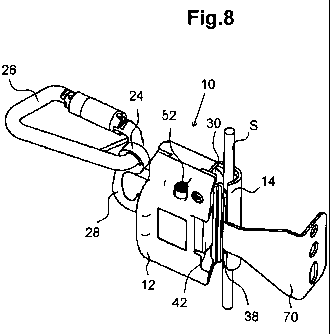
Figure 8 shows the shuttle according to the invention, running over an
intermediate support for the cable of a climbing protection system.
Figures 9 and 10 show a second locking device in the correct and reverse
orientation of the shuttle respectively.
Figure 11 shows the shuttle, wherein the two holes in the casing of the
shuttle for the second locking device can be seen.
Ways of carrying out the invention
The shuttle 10 is part of a climbing protection system and is guided
along a cable S. If a user falls, the shuttle 10 grips the cable S. The
shuttle
10 has a rectangular casing 12, a guiding mechanism 14 in the form of a
channel along one longitudinal side of the casing 12, a clamping lever 16
with attachment eye 24 and a first and second locking device 50, 80. The
clamping lever 16 is rotatably housed in the shuttle 10 and is used in
CA 02698433 2010-03-03
9
shuttles which are provided with a cable S, tensioned at an angle or
vertically, for a climbing protection system.
Figure 1 shows the shuttle in its non-clamping, normal position, in
which the clamping lever 16 does not project into the guiding mechanism
14. Although the clamping lever 16 is pretensioned by means of a
clamping lever spring 20 into a clamping position, in which it clamps the
shuttle 10 onto the cable S, when in use the clamping lever 16 is swivelled
into the release position under the weight of the shuttle 10. As a result the
clamping lever 16 does not normally lie against the cable S in the guiding
mechanism 14 of the shuttle 10, with the result that there is no friction and
a movement of the shuttle 10 on the cable S is not affected.
The clamping lever 16 of Figure 1 has two arms, and its first arm 22,
facing the cable S, is bent downwards at an angle. When the first arm 22 of
the clamping lever 16 is pointing downwards at an angle, the shuttle 10 is
attached to the cable S in the right orientation, as it can then act as a fall
prevention means. Furthermore the outer surface of the first arm 22 of the
clamping lever facing the cable S is rounded so that the outer surface
carries out an eccentric movement when the clamping lever 16 is moved
into the clamping position. At the end of its second arm, protruding from
the casing, the clamping lever 16 possesses an attachment eye 24 for
fastening a carabiner 26 of the full body harness. Furthermore a damping
element 28 is provided, the operation of which is described later. Guide
rollers 30 in the guiding mechanism 14 of the shuttle 10 serve to guide the
cable S of the climbing protection means.
The dimensioning of the guiding mechanism 14 is suitable for cables S
with different diameters (e.g. 8 mm, 10 mm, 3/8 inch). In order that the
clamping lever 16 also does not touch thicker cables S in the guiding
mechanism 14 during use of the shuttle 10, the relationship between the
elastic force of the clamping lever spring 20 and the shuttle 10's own
weight must be chosen accordingly.
Figure 2 shows the clamping lever 16 represented in Figure 1 in the
clamping position which it assumes if a user falls. In the event of a fall,
only
the torque produced by the clamping spring still acts on the clamping lever
CA 02698433 2010-03-03
16, and no longer the greater torque exerted in the opposite direction, that
is produced by the weight of the shuttle when it is suspended from the
safety harness. The clamping lever 16 is therefore brought, by the
pretensioning of the clamping lever spring 20, into the clamping position in
5 which the
end of the first arm 22 of the clamping lever 16 presses against
the cable in the guiding mechanism 14, with the result that the shuttle 10
grips the cable S. In other words, due to the eccentric form of the first arm
22 of the clamping lever 16, the shuttle 10 grips the cable Sand prevents a
free fall of the user.
10 As shown
in Figures 1 and 2, the clamping lever 16 has a damping
element 28, which is formed by a non-rectilinear section of the clamping
lever 16 at its second end. The damping element 28 is released when
subjected to a specific load, for example if the user falls and the clamping
lever 16 is moved into the clamping position. The impact force is thus
dampened, reducing the risk of injury to the user.
Figure 3 shows a sectional view of a shuttle 10 with a symmetrically
formed clamping lever 32. Here the clamping lever 32 is also rotatably
mounted in the shuttle 10, but formed in the shape of an anchor, with the
result that it is symmetrical along its longitudinal axis. Unlike the clamping
lever 16 of Figures 1 and 2, the end of the first arm 22a of the clamping
lever 32 is formed substantially perpendicular to its longitudinal axis. Due
to the symmetrical form of the clamping lever 32 two clamping lever
springs 20 are necessary, which hold the clamping lever 32 in a central
position. An advantage of the symmetrical clamping lever 32 is that it can
be used on horizontal, inclined and vertical cables. As the clamping lever
32 is formed symmetrically, according to this embodiment the shuttle 10
can be attached to the cable in both directions. Therefore the shuttle 10
according to Figure 3 requires no second locking device which prevents
the shuttle being attached in the wrong orientation.
Spring mountings 34 for the guide rollers 30 are provided at the ends of
the guiding mechanism 14. The spring-mounted guide rollers 30 serve to
guide the cable and to decelerate the shuttle 10 to a certain extent during
the movement on the cable S. In the event of a fall the shuttle 10 is
CA 02698433 2010-03-03
11
somewhat deceleated by the rollers 30, with the result that the clamping
lever 16 swivels somewhat due to the weight of the user who has just lost
his hold, and touches the cable S with the lower end of its first arm and
jams, with the result that the shuttle 10 locks in place on the cable S.
The guiding mechanism 14 is a channel with a continuous lateral gap
38. The gap 38 can be opened or partly closed by means of a slider 40.
The first locking device blocks the slider 40 normally in the partly closed
position of the gap 38.
The slider 40 is shown in Figure 4 in several parts. The slider 40 has a
grip 42 with which the user operates the slider 40, and a plate 44 from
which the grip 42 projects and which is shifted according to the actuation of
the grip 42. The individual components of the slider 40 are screwed or
welded together or the slider 40 is formed from a single piece (e.g. as a
cast part). Both metallic and also non-metallic materials can be used for
the slider 40.
Helical compression springs 46 for the slider 40 are arranged between
a casing part 48 of the shuttle 10 and the slider 40. As can be seen from
Figure 5, two helical compression springs 46 are provided for the slider 40.
The helical compression springs 46 serve to pretension the slider 40 into
the position at least partly closing the gap 38 (Fig 4).
Figure 5 shows the shuttle 10 of Figure 4 with opened gap 38; in other
words, the slider 40 is retracted. This allows the cable S to be inserted
into,
or respectively removed from, the guiding mechanism 14. The opened
state of the gap 38 is thus achieved by pressing the first locking device 50,
i.e. the pin 52, against the force of the helical compression springs 54 and
then moving the slider 40 against the force of the helical compression
springs. The pin 52 encounters the stop 58 on the shuttle casing. In other
words, when the first locking device 50 and then the slider 40 are
respectively moved into their second position, the gap 38 in the guiding
mechanism 14 is opened (Fig. 5). The motion path of the slider 40 is so
great that the shuttle 10 can on the one hand be attached to a cable S with
a relatively large diameter (e.g. 10 mm) and on the other hand, in the partly
CA 02698433 2010-03-03
12
closed state of the gap 3, the shuttle 10 can be secured, as shown in
Figure 4, to a cable with a relatively small diameter (e.g. 8 mm).
Figure 6 shows the first locking device 50 of the shuttle 10 without
shuttle housing 12. The first locking device 50 has a pin 52, which has an
area 52a with a reduced diameter in its longitudinal direction. The pin 52 is
pretensioned upwards into its first position by a helical compression spring
54. When the pin 52 is in the first position, the slider 40 is blocked and
cannot therefore be moved. This blocking is achieved by a detent lug 60 on
the slider 40 encountering an area of the pin 52 with a large diameter. The
slider 40 is thereby blocked in its first position, into which it is also
pretensioned by the helical compression springs 46 for the slider 40. In this
first position of the slider 40 the gap 38 in the guiding mechanism 14 is
partly closed as shown in Figure 4, i.e. to the extent that on the one hand
the cable S cannot fall out and on the other hand an intermediate support
can be passed over.
The gap 38 is partly closed whenever the user does not actuate the pin
52 or the slider 40. This is because both the pin 52 and the slider 40 are
pretensioned into their respective first positions by means of helical
pressure springs 46 and 54 respectively.
Figure 7 shows the slider 40 in its retracted, second position, in which
the gap 38 is then open. The pin 52 is pressed and lies against a stop 58,
with the result that the area 52a with a reduced diameter is aligned with the
detent lug 60 on the slider 40, in order to allow a shifting of the slider 40,
with the result that, as shown in Figure 6, the gap 38 is opened by a
movement of the slider 40. As the slider 40 can be moved only against the
force of the helical pressure springs 46, these are compressed when the
gap is opened, as can be seen from a comparison of Figures 6 and 7.
As shown in Figures 5 and 6, the slider 40 is moved substantially at
right angles to the guiding mechanism 14 and the pin 52. The shuttle 10
can thereby be operated with one hand. For example the pin 52 can be
pressed into its second position with the thumb and the slider 40 can then
be moved into its second position with the fingers of the same hand in
order to open the gap 38 in the shuttle 10. On the other hand, if the user
CA 02698433 2010-03-03
13
exerts no force on the pin 52 and the slider 40, they return to their first
positions. Thus the shuttle 10 according to the invention allows a
particularly simple operation, at the same time preventing an inadvertent
release of the shuttle 10 from the cable S. Furthermore, the shuttle 10 can
be of an extremely compact design because of the described arrangement
of the individual elements, with the result that the shuttle casing 12 can be
designed ergonomically.
Figure 8 shows the shuttle 10 according to the invention running while
in use over an intermediate support 70 for the cable S of a climbing
protection system. The slider 40 and the pin 52 are situated in their first
position, with the result that the gap 38 in the guiding mechanism 14 is
partly closed. The remaining opening of the gap on the one hand is large
enough for the shuttle 10 to be able to run over the intermediate support 70
for the cable S, without having to open the gap 38. On the other hand the
gap 38 is closed far enough for the cable S not to be able to slip out of the
guiding mechanism 14. The intermediate support 70 is fastened directly to
a structure, a ladder or another suitable base.
Figure 9 shows a preferred embodiment of the shuttle 10, wherein a
second locking device 80 is provided which prevents the shuttle 10 from
being attached to the cable S in the reverse orientation. The second
locking device 80 has a bolt 82, which is movably housed in a blind hole 84,
open at one end, in the slider 40. The blind hole 84 is situated at the end of
the slider 40 against which the pressure springs 46 press. The blind hole
84 possesses a lower closed end 86 and an upper opened end 88. If the
shuttle 10 is situated in the correct orientation relative to the cable S, the
bolt 82 encounters the lower, closed end 86 of the blind hole 84 under its
own weight and is completely accommodated in the blind hole 84. In this
position the mechanism of the slider 40 can move freely.
However, if the shuttle 10 is situated in the reversed orientation relative
to the cable S (Figure 10), the bolt 82 drops, under its own weight, through
the opened end of the blind hole 84 into a hole 90 in the casing 12 of the
shuttle 10. The slider 40 is thereby locked in place and can no longer be
moved. Two holes 90a and 90b are provided in the casing 12 of the shuttle
CA 02698433 2010-03-03
14
(Fig. 10). If the slider 40 is situated in its first position, in which it
closes
the gap 38, the bolt 82 drops into the first hole 90a if the shuttle 10 is
wrongly oriented. The slider 40 can now no longer be brought into its
second position and the gap 38 cannot be opened. If the slider 40 is
5 already situated in the second position, the gap 38 is thus already
opened,
and if the shuttle 10 is only then turned round and an attempt made to
attach it to the cable S the other way round, the bolt 82 drops into the
second hole 90b in the casing 12 of the shuttle 10. Now the slider 40 can
no longer be brought into the first position in order to close the gap 38,
with
10 the result that the shuttle 10 does not remain on the cable S.