Note: Descriptions are shown in the official language in which they were submitted.
CA 02698712 2010-04-06
TITLE
GEOTHERMAL LINER SYSTEM WITH PACKER
FIELD OF THE INVENTION
[1] The present invention relates to the production of fluids within a
wellbore.
More particularly, the present invention relates to the isolation of producing
zones
within a wellbore using a liner system of a liner with packers. More
particularly, the
present invention relates to sealing a mandrel of the liner within a wellbore
using
packers that prevent fluids from flowing between producing zones.
Additionally,
the present invention relates to packers that allow mandrels of the liner to
slide
longitudinally therein, so as to account for exposure to wellbore conditions.
BACKGROUND
[2] It is well known that land formations that produce oil and gas have
different
"zones" where different mixtures of oil and gas are produced, where other
fluids-
such as water-are produced, and where no fluids are produced at all. An oil
and gas
wellbore can pass through any number and combination of these zones so as to
maximize the production of oil and gas from the land formation.
1
CA 02698712 2010-04-06
[3] Open-hole completions are commonly used for producing oil and gas in a
wellbore. Open-hole completions are particularly useful in slant-hole wells.
In these
wells, the wellbore may be deviated and run horizontally for thousands of feet
through a producing zone. It is often desirable to provide annular isolators,
or
packers, along the length of the horizontal production tubing to allow
selective
production from, or isolation of, various portions of the producing zone.
[4] In open-hole wells, standard casing is cemented only into upper portions
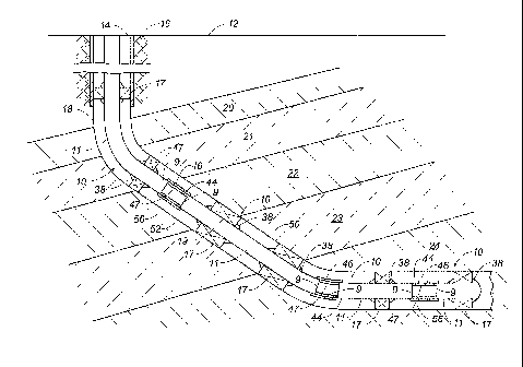
of
the well, and not through the producing zones. A liner then runs from the
bottom of
the cased portion of the well down through the various zones in the wellbore.
In a
typical production of oil and gas in a wellbore, production tubulars or
casings are
inserted in the wellbore. In open-hole completions, nothing supports the
wellbore
from collapse upon itself. Thus, the liner is used to fill the interior of the
wellbore
and to support the walls of the wellbore. Liners are typically run into
uncased
portions of wellbores. It is desirable for liners to minimize the annular
space between
the liner and the wellbore wall so as to provide mechanical support and
restrict or
prevent annular flow of fluids outside the production tubing of the liner.
However,
due to irregularities in the wellbore wall, liners do not prevent annular flow
in the
wellbore. For this reason, a liner system includes packers that are used to
stop
annular flow of fluids around the liner. Packers provide annular seals, or
barriers,
between the liner and the wellbore wall to isolate various zones within the
wellbore
2
CA 02698712 2010-04-06
and along the liner. A mandrel and a packer are components that can be
installed in
the liner, along with the regular tubular joint casings as part of a liner
system.
[5] A problem associated with oil and/or gas production within a wellbore is
that
when a wellbore passes through certain zones, such as a water zone, water can
enter
the annular space between the liner and the wellbore wall and mix with oil
and/or
gas. Thus, there is a need to isolate water zones (or other non-desirable
zones) from
oil and/or gas zones.
[6] Another problem associated with oil and/or gas production within a
wellbore
is that various production zones can have different natural pressures. Zones
of
different pressures must be isolated from each other so as to prevent flow in
the
wrong direction and to allow production from the low pressure zones. Thus,
where
multiple zones are penetrated by the same wellbore, there is a need to isolate
the
zones to allow separate control of fluid flow in each zone for more efficient
oil
and/or gas production.
[7] A problem associated with typical liner systems is the inability to move
the
liner relative to the packers once the packers have expanded within the
wellbore.
Thus, there is a need for a liner system with a liner and packers that allows
for the
longitudinal movement of the liner relative to the expanded packers within the
3
CA 02698712 2010-04-06
wellbore.
[8] Various patents have been issued relating to liner systems. For example,
U.S.
Patent No. 7,404,437, issued on July 29, 2008 to Brezinski et al., discloses
an
apparatus and method for forming an annular isolator in a borehole after the
installation of production tubing. Annular seals are carried in or on
production
tubing as it is run into a borehole. In conjunction with expansion of the
tubing, the
seals are deployed to form annular isolators. An inflatable element carried on
the
tubing can be inflated with a fluid carried in the tubing and forced into the
inflatable
element during expansion of the tubing. Reactive chemicals can be carried in
the
tubing and injected into the annulus to react with each other and also with
ambient
fluids so as to increase in volume and harden into an annular seal. An
elastomeric
sleeve, ring, or band carried on the tubing may be expanded into contact with
a
borehole wall and may have its radial dimension increased in conjunction with
tubing expansion to form an annular isolator.
[9] U.S. Patent No. 7,373,973, issued on May 20, 2008 to Smith et al.,
discloses a
bridge plug having a segmented backup shoe, and a split-cone extrusion
limiter. The
extrusion limiter has a two-part conical retainer positioned between packer
elements
and the segmented backup shoe. The extrusion limiter blocks packer element
extrusion though spaces between backup shoe segments. In one embodiment, two
4
CA 02698712 2010-04-06
split-cone extrusion limiters are used together and positioned so that each
split cone
extrusion limiter covers gaps in the other extrusion limiter. The two split-
cone
extrusion limiters block packer element extrusion though gaps between backup
shoe
segments regardless of their orientation relative to the segmented backup
shoe. In
another embodiment, a solid retaining ring is positioned between a split
retaining
cone extrusion limiter and a packer element. The solid retaining ring resists
extrusion of packer elements into spaces in the split-cone extrusion limiter
or
limiters.
[10] U.S. Patent No. 7,392,851, issued on July 15, 2008 to Brennan, III et
al.,
discloses an inflatable packer assembly that has a first expandable tubular
element
having a pair of ends, a first pair of annular end supports for securing the
respective
ends of the first tubular element about a mandrel disposed within the first
tubular
element, and a first annular bracing assembly deployable from one of the end
supports for reinforcing the first tubular element upon pressurization and
expansion
thereof. An end of the first annular bracing assembly is pivotally connected
to one of
the end supports for reinforcing the first tubular element upon pressurization
and
expansion thereof. An opposite end of the first annular bracing assembly is
expandable. One of the end supports is movable. The other end support is fixed
with respect to the mandrel. The first annular bracing assembly has a slats
arranged
in an annular configuration and pivotally connected at one of to the movable
end
5
CA 02698712 2010-04-06
support. Each of the slats has a width that increases from its pivotally
connected end
to its other end.
[11] U.S. Patent No. 7,387,170, issued on June 17, 2008 to Doane et al.,
discloses a
packer device that includes a central packer mandrel and a radially-
surrounding
expansion mandrel. A slip mandrel carrying wickers surrounds the expansion
mandrel and is secured in place upon the expansion mandrel by an annular
retaining ring. The slip mandrel is secured to the retaining ring by screw
connectors
that pass through the slip mandrel and into retainer segments. The retaining
ring is
clamped between the slip mandrel and segments. The packer device carries a
fluid
seal that is made up of a thermoplastic material with elastomeric energizing
elements.
[12] U.S. Patent No. 7,387,158, issued on June 17, 2008 to Murray et al.,
discloses a
packer that has a main sealing element that swells after a delay that is long
enough
to get the sealing element into a proper position. A sleeve is removed from
the
packer so as to allow well fluids to contact the main sealing element so as to
start the
swelling process. The main sealing element swells until the surrounding
tubular or
the surrounding wellbore is sealed. Sleeves that remain above and below the
main
sealing element preferably swell in a longitudinal direction so as to abut the
main
sealing element and increase the contact pressure of the main sealing element
6
CA 02698712 2010-04-06
against the surrounding tubular or wellbore. The longitudinally-swelling
members
can be covered to initiate their growth after the main sealing element has
started or
completed a swelling action. The longitudinally-swelling members can be
constrained against radial growth to direct swelling action in a longitudinal
direction. Extrusion barriers above and below the main sealing element can
optionally be used.
[13] U.S. Patent No. 7,314,092, issued on January 1, 2008 to Telfer, discloses
a
packer tool for mounting on a work string that has a body with packer elements
thereon, and a sleeve positioned around the packer elements so as to compress
the
packer elements. The packer tool is set by movement of the tool body relative
to the
sleeve. The sleeve includes a retaining member. The retaining member is
removable
between a first and a second position. In the first position, the retaining
member
prevents movement of the sleeve relative to the tool body so as to prevent
setting of
the packer tool. In the second position, the retaining member releases the
tool body
so as to arrest a movement of the sleeve. In the second position, the
retaining
member also facilitates compression of the packer elements so that the tool
can be
set.
[14] U.S. Patent No. 7,143,832, issued on December 5, 2006 to Fyer, discloses
an annular packer arranged on the outside of the production tubing. The packer
has
7
CA 02698712 2010-04-06
a core that has an elastic polymer that swells by the addition of
hydrocarbons. The
core can be surrounded by an external mantel of rubber. The external mantel of
rubber is permeable to hydrocarbons and may be equipped with a reinforcement.
The core swells by absorption of hydrocarbons and the packer expands
accordingly.
The expansion of the packer seals the annular space between the production
tubing
and the well wall.
[15] U.S. Patent No. 6,848,505, issued on February 1, 2005 to Richard et al.,
discloses a method of sealing casing or liners in a wellbore. Strands of
casing or
liners receive a jacket bonded to the outer surface. Preferably, the jacket is
a rubber
compound bonded to the outer wall. The rubber compound swells at a
predetermined rate in response to contact with fluids in the well. The casing
or liner
can be expanded with a swage preferably prior to the onset of the swelling of
the
jacket. Packers and sealing hangers can be added at the extremes of the casing
or
liner string to further secure against channeling between adjacent formations.
[16] U.S. Patent No. 7,228,917, issued on June 12, 2007 to Thomson, discloses
an
apparatus and method for creating a seal in a bore hole annulus. A conduit
within a
wellbore has an outer surface covered with an elastomeric material that can
expand
and/or swell when the material comes into contact with an actuating agent. The
conduit is an expandable conduit. The conduit is located inside a second
conduit
8
CA 02698712 2010-04-06
and radially expanded therein. The actuating agent can be naturally occurring
in the
bore hole or can be injected or pumped into the bore hole so as to expand or
to swell
the elastomeric material to create the seal.
[17] U.S. Patent No. 7,121,352, issued on October 17, 2006 to Cook et al.,
discloses
an apparatus that has a zone-isolation assembly. The assembly has a solid
tubular
member. The solid tubular member has external seals. A perforated tubular
member
is coupled to the solid tubular member. A shoe is coupled to the zone-
isolation
assembly. The perforated tubular members include an elastic sealing member
that is
coupled to the perforated tubular member. The elastic sealing member covers
the
perforations of the perforated tubular member.
[18] It is an object of the present invention to control the flow of fluids in
a
producing wellbore.
[19] It is another object of the present invention to prevent the flow of
water into a
producing liner.
[20] It is another object of the present invention to produce oil and gas from
zones
having different pressures.
9
CA 02698712 2010-04-06
[21] It is still another object of the present invention to provide a liner
system,
having a mandrel-packer assembly that can be opened and closed within the
wellbore so as to allow or prevent a flow of fluid into the producing liner.
[22] It is another object of the present invention to provide a liner system,
having a
mandrel-packer assembly, wherein the mandrel longitudinally extends within the
interior of packers after the packers have been locked in position by
expansion
within the wellbore.
[23] It is another object of the present invention to maximize oil and gas
production for any number and combination of zones within a wellbore.
[24] It is still another object of the present invention to provide a liner
system,
having a mandrel-packer assembly, wherein the mandrel that can be installed
with
packers affixed thereto and that can adjust longitudinally through the
packers, after
the packers are expanded in place against the wellbore.
[25] It is another object of the present invention to provide a liner system
that can
be used in vertically and horizontally-extending wells.
[26] It is another object of the present invention to provide a liner system
for
CA 02698712 2010-04-06
injection wells and producing wells.
[27] It is another object of the present invention to isolate the various
zones of a
wellbore that have no casing or liner.
[28] It is another object of the present invention to support the walls of a
wellbore
with expandable packers.
[29] It is another object of the present invention to provide a liner system
that is
easily placed within a wellbore.
[30] It is still another object of the present invention to provide a liner
system that
withstands wellbore conditions associated with oil and gas production,
including
but not limited to environmental conditions related to geothermal temperatures
and
pressure.
[31] It is another object of the present invention to provide a liner system
where
the packer is releasably affixed to the outer surface of the mandrel.
[32] These and other objects and advantages of the present invention will
become
apparent from a reading of the attached specification and appended claims.
11
CA 02698712 2010-04-06
SUMMARY OF THE INVENTION
[33] The present invention is a geothermal liner system with packer that seals
a
producing zone within a wellbore, comprising a plurality of joint casings, a
mandrel
placed in an interior of the wellbore in sequence with the joint casings, a
packer
releasably affixed around an outer surface of the mandrel, and a sleeve
positioned
adjacent an end of the mandrel. The liner is generally tubular because the
joint
casings and mandrels are tubular-shaped. The mandrel is a component within the
liner. The packer is of a material that is expandable upon contact with fluids
in the
wellbore, and there can be more than one packer in the liner system. The
mandrel is
longitudinally slidable within an interior of the packer. The sleeve has a
plurality of
perforations in a wall thereof and is independently activated to open or close
the
perforations with respect to the wellbore. The sleeve is placed in the open
position so
as to allow production of fluid from the corresponding wellbore zone. The
sleeve can
be placed in the closed position so as to prevent fluid flow into the liner,
such as
during installation and positioning of the mandrel in the wellbore.
[34] The packer comprises a packing structure having a channel formed therein,
a
packer element received in the channel of the packing structure, and a fusible
link
connected to the packing structure. The packing structure is slidable relative
to the
12
CA 02698712 2010-04-06
outer surface of the mandrel, after the packer element has expanded in an
annular
space between the packing structure and the wellbore upon contact with the
fluids
in the wellbore. The fusible link is releasably affixed to the outer surface
of the
mandrel. During installation and while traveling through the wellbore, the
fusible
link fixes the packer to the mandrel. After reaching the planned destination,
the
fusible link releases, allowing the longitudinal sliding relation between the
packer
and mandrel.
[35] The packing structure comprises a tubular element slidably positioned on
the
outer surface of the mandrel, a first end portion affixed to an end of the
tubular
element, and a second end portion affixed to an opposite end of the tubular
element.
The first end portion and the second end portion and the tubular element form
the
channel.
[36] The fusible link comprises a first connection affixed to the first end
portion of
the packing structure, and a second connection affixed to the second end
portion of
the packing structure. The first connection is releasably affixed to the outer
surface
of the mandrel. The second connection is releasably affixed to the outer
surface of
the mandrel. The first and second connections are suitable for dissolving upon
contact with the fluids in the wellbore. The mandrel can be a chromed mandrel
and
can be expanded longitudinally through the wellbore upon exposure to wellbore
13
CA 02698712 2010-04-06
conditions. The sleeve has an inner diameter smaller than an outer diameter of
the
mandrel. The plurality of perforations are in fluid communication with an
interior of
the liner through the mandrel, sleeve or the joint casings.
[37] The present invention is an apparatus for sealing a producing zone within
a
wellbore comprising a first packing assembly having a mandrel and a packer, a
sleeve having an end positioned adjacent an end of the mandrel of the first
packing
assembly, and a second packing assembly having a mandrel and a packer. The
mandrel of the second packing assembly has an end positioned adjacent an
opposite
end of the sleeve. The packer of the first packing assembly is releasably
affixed to the
mandrel of the first packing assembly. The packer of the second packing
assembly is
releasably affixed to the mandrel of the second packing assembly. The sleeve
has a
plurality of perforations in a wall thereof. The mandrels of the first and
second
packing assemblies are slidable relative to the packers, after the packers
have
expanded. The sleeves are separately controlled to expose the perforations to
the
isolated wellbore selectively. The perforations are selectively opened and
closed
without regard to the expansion and sliding relation between the mandrels and
packers. The plurality of perforations of the sleeve can be in fluid
communication
with the liner through an interior of the mandrel at the first packing
assembly and an
interior of the mandrel at the second packing assembly.
14
CA 02698712 2010-04-06
[38] The packers of the first and second packing assemblies each have a
packing
structure having a channel therein, a packer element received in the channel
of the
packing structure, and a fusible link connected to the packing structure. The
packing structure is slidable relative to an outer surface of the mandrel. The
packer
element is expandable in an annular space between the packing structure and
the
wellbore upon contact with fluids in the wellbore. The fusible link is
releasably
affixed to the outer surface of the mandrel. The fusible link fixes the
packing
structure in place until the wellbore conditions release the fusible link. The
packing
structure comprises a tubular element slidably positioned on the outer surface
of the
mandrel, a first end portion affixed to an end of the tubular element, and a
second
end portion affixed to an opposite end of the tubular element. The first end
portion
and the second end portion and the tubular element form the channel. The
fusible
link has a first connection affixed to the first end portion of the packing
structure,
and a second connection affixed to the second end portion of the packing
structure.
The first connection is releasably affixed to the outer surface of the
mandrel. The
second connection is releasably affixed to the outer surface of the mandrel.
As such,
the first and second connections are suitable for dissolving upon contact with
the
fluids in the wellbore.
CA 02698712 2010-04-06
BRIEF DESCRIPTION OF THE DRAWINGS
[39] FIGURE 1 shows a cross-sectional view of a well bore in a land formation,
with the preferred embodiment of the apparatus of the present invention
therein.
[40] FIGURE 2 shows a cross-sectional view of the wellbore in the land
formation,
with the preferred embodiment of the present invention adjusted therein.
[41] FIGURE 3 shows an isolated cross-sectional view of the apparatus of the
present invention within a wellbore.
[42] FIGURE 4 shows an isolated cross-sectional view of first and second
packer
assemblies within a wellbore fixedly positioned on the mandrel during
installation,
the perforations being closed to the interior of the mandrel.
[43] FIGURE 5 shows an isolated cross-sectional view of the first and second
packing assemblies, with the packers expanded within the wellbore and the
fusible
link released, the mandrels being longitudinally moveable so as to allow for
expansion by geothermal heat, and the perforations being open for fluid to
flow into
the mandrel.
16
CA 02698712 2010-04-06
[44] FIGURE 6 shows an isolated cross-section view of the first and second
packing assemblies, with the packers expanded within the wellbore and the
fusible
link release, the mandrels still being longitudinally moveable so as to allow
for
expansion, and the perforations being closed by the sleeve to block the flow
of fluid
into the mandrel so as to allow production of fluid from another zone.
DETAILED DESCRIPTION OF THE DRAWINGS
[45] Referring to FIGURE 1, there is shown a cross-sectional view of a land
formation 16, with the preferred embodiment of the apparatus 10 of the present
invention inserted within a wellbore 50 that has been formed in the land
formation
16. The land formation 16 has a water-producing layer 20, a non-producing
layer 21
below the water-producing layer 20, an oil-and-gas layer 22 below the non-
producing layer 21, another water layer 23 below the oil-and-gas layer 22, and
another oil-and-gas layer 24 below the water layer 23. The wellbore 50 extends
vertically and diagonally through the water-producing layer 20. The wellbore
50
extends diagonally through the non-producing layer 21, the oil-and-gas layer
22, the
other water layer 23, and a portion of the oil-and-gas layer 24. The wellbore
50
extends horizontally through oil-and-gas layer 24. The various layers 20, 21,
22, 23
and 24 are also referred to as zones. These zones can reside at a great depth
below
the surface 12 of the land formation 16. Near the surface 12 of the land
formation 16,
17
CA 02698712 2010-04-06
the wellbore 50 has casing 14 on the walls 18 thereof. The casing 14 adds
structural
integrity to the wellbore 50. The casing 14 is not used within the wellbore 50
when
the wellbore 50 turns diagonally or horizontally through the land formation
16.
Because the wellbore 50 cuts through the water-producing zones 20 and 23 and
the
oil-and-gas producing zones 22 and 24, water and oil and gas will seep into
the
wellbore 50. These fluids will mix and be urged upward towards the surface 12
of
the land formation 16 unless an obstruction keeps them from moving upwardly in
the wellbore 50.
[46] The apparatus 10 of the present invention seals the producing zones 20,
22, 23,
and 24 from one another within the wellbore 50, and only allows the oil-and-
gas
producing zones 22 and 24 to produce fluid that moves upwardly through the
liner
by joint casings or mandrels 11 toward the surface 12 of the land formation 16
within
the wellbore 50. The apparatus 10 has a mandrel 11 placed in an interior 52 of
the
wellbore 50. The liner has a generally tubular shape because the joint casings
and
mandrels 11 have a tubular shape. The joint casings are tubular elements that
extend
the length of the liner through the wellbore. A packer 17 is releasably
affixed around
an outer surface 15 of the mandrel 11. The packer 17 is of a material that is
expandable upon contact with fluids in the wellbore 50. There can be more than
one
packer 17 in a system of the present invention 10. The mandrel 11 is slidable
within
the interior 19 of the packer 17, when the packer 17 is expanded and released.
A
18
CA 02698712 2010-04-06
sleeve 44 is positioned adjacent an end 9 of the mandrel 11 and has
perforations 46 in
a wall 47 thereof.
[47] In FIGURE 1, packers 17 are placed so that any water produced from zone
20
cannot move upwardly or downwardly within the wellbore 50. The annular space
56 between the outer surface 15 of the mandrel 11 and the wall 18 of the
wellbore 50
may fill with water in the region between packers 17; however, the water will
remain
within this space and not be produced. Any water that is produced in zone 23
is also
blocked from flowing within the wellbore 50 by packers 17. Although the
mandrel
11 passes by the water-producing zones 20 and 23, there are no sleeves with
perforations that allow the water to flow into the interior 19 of the mandrel
11 so as
to be produced. In the oil-and-gas zones 22 and 24, sleeves 44 are
incorporated with
the mandrel 11 so as to allow oil and gas to enter the perforations 46 of the
sleeve 44
and thus enter the liner for production at the surface 12. The ends 9 of the
mandrel
11 and the wellbore 50 of FIGURE 1 are spaced apart so as to allow fluids of
oil and
gas to enter the perforations 46 of the sleeves 44 and into the liner.
[48] As will be explained in more detail below, the sleeves 44 can be placed
in an
open position, for example in FIGURE 1, so that fluid can flow through the
sleeves
44 and into the liner, including the mandrels 11. The mandrels 11 are
longitudinally
slidable within the wellbore 50, relative to the fixed packers, after the
packers 17
19
CA 02698712 2010-04-06
swell within the wellbore 50, so as to account for thermal expansion of the
mandrel
11 due to wellbore conditions, such as geothermal heat. Prior to the apparatus
10 of
the present invention, this was not possible. The wellbore conditions would
expand
and rupture the sealed packer installations because the packers 17 remained
fixed on
the liner. In the apparatus 10, the fusible links of the packer 17 that
affixed the
packer 17 to the outer surface 15 of the mandrel 11 are released from the
outer
surface 15 after the packers 17 swelled within the wellbore 50. Thus, the
mandrels 11
are now longitudinally slidable within the interior 19 of the packers 17
relative to the
packers 17, allowing for stability of the entire liner system through various
environmental stress in the wellbore.
[49] Referring to FIGURE 2, there is shown a cross-sectional view of the land
formation 16, with the liner, including joint casings and mandrels 11 moved
relative
to the packers 17 within the wellbore 50. The sleeve 44 in zone 24 that
produces oil
and gas is shown in the open position so as to allow oil and gas fluids to
flow
through the perforations 46 in the sleeves 44 and into the interior 13 of the
liner. The
sleeves 44 are separately controlled with regard to the thermal expansion of
the liner,
including the joint casings and mandrels 11. The sleeves 44 are selectively
opened,
and the liner system of the present invention maintains the sealed zones,
accounting
for various wellbore conditions, by movable mandrels 11. The sleeves 44 are
tubular
in shape so as to fit over and into the ends 9 of the mandrels 11. In FIGURE
2, the
CA 02698712 2010-04-06
ends 9 of the mandrels 11 in zone 22 are longitudinally expanded because of
geothermal heat in the wellbore. The sleeve 44 maintains control of the fluid
access
to the wellbore in any expanded or non-expanded status of the mandrels.
Production of oil and maintenance of the fluid connection are not determined
by
particular mandrel movement because collection may need to occur in a
particular
zone without regard to any expansive movement of any particular mandrel 11.
The
present invention presents a simple and effective solution to maintain the
sealed
zones without ruptures from various wellbore conditions, such as geothermal
powered expansion, and fluid access controlled by sleeves. The present
invention is
a more stable system to install a liner with the packers in the proper
locations and to
maintain the sealed zones for fluid collection.
[50] The movement of the mandrels 11 relative to the packers 17 is made
possible
by the fusible links 38 releasably attached to each packer. In prior art, each
packer 17
would be fixed to the outer surface 15 of the mandrels 11. In the present
invention,
the packersl7 are affixed to the outer surface 15 of the mandrels 11 when the
packers
17 and mandrels 11 are inserted within the wellbore 50. After the packers 17
expand
within the wellbore 50 so as to fix the apparatus 10 within the wellbore 50,
the
fusible links 38 release from the outer surface 15 of the mandrels 11 so as to
allow the
mandrels 11 to longitudinally expand and slide within the interior 19 of the
packers
17. The packers 17 thus stay in place within the mandrels 11 and support both
the
21
CA 02698712 2010-04-06
wall 18 of the wellbore 50 and the outer surface 15 of the mandrels 11 within
the
wellbore 50 while the mandrels 11 adjust to wellbore conditions within the
interior
19 of the packers 17.
[51] Referring to FIGURE 3, there is shown an isolated cross-sectional view of
a
packer 17 and mandrel 11 inserted within the wellbore 50. The apparatus 10 is
shown as residing within the wellbore 50 before the packer 17 has expanded
within
the wellbore 50. The mandrel 11 is a chromed mandrel. The chromed mandrel is
resistant to certain contaminants and corrosives that are contained in the
fluids that
are produced within the wellbore 50. The packer 17 is releasably affixed to
the outer
surface 15 of the mandrel 11.
[52] The packer 17 has a packing structure 25. The packing structure has a
channel
27 formed therein. The packer 17 has a packer element 36 that is received
within the
channel 27 of the packing structure 25. The packer element 36 is expandable in
the
annular space 56 between the packer structure 25 and the wellbore 50 upon
contact
with the fluids in the wellbore 50. The packer 17 also has a fusible link 38
that is
connected to the packer structure 25. The fusible link 38 is releasably
affixed to the
outer surface 15 of the mandrel 11. The packing structure 25 can be slidable
relative
to the outer surface 15 of the mandrel 11, after the fusible links release.
Specifically,
the packing structure 25 has a tubular element 26 that is slidably positioned
on the
22
CA 02698712 2010-04-06
outer surface 15 of the mandrel 11. A first end portion 32 is affixed to an
end 28 of
the tubular element 26. A second end portion 34 is affixed to an opposite end
30 of
the tubular element 26. The first end portion 32 and the second end portion 34
and
the tubular element 26 form the channel 27 of the packing structure 25. The
tubular
element 26 extends radially outwardly from the outer surface 15 of the mandrel
11
for a distance less than a distance which the first and second end portions 32
and 34
extend radially outwardly from the outer surface 15 of the mandrel 11. A
packing 31
is placed on a bottom of each of the first and second end portions 32 and 34
so that
the first and second end portions 32 and 34 slide easily along the outer
surface 15 of
the mandrels 11. The fusible link 38 of the packer 17 has a first connection
40 affixed
to the first end portion 32 of the packing structure 25 and a second
connection 42
affixed to the second end portion 34 of the packing structure 25. The first
connection
40 is releasably affixed to the outer surface 15 of the mandrel 11. The second
connection 42 is releasably affixed to the outer surface 15 of the mandrel 11.
The
first and second connections 40 and 42 are suitable for dissolving upon
exposure to
wellbore conditions. Particular wellbore conditions, such as temperature and
pressure, can be pre-determined for a liner system to be placed in the
wellbore 50.
The mandrel 11 is also expandable upon exposure to wellbore conditions. Once
fluids from the land formation fill within the annular space 56 of the
wellbore 50, the
packer element 36 expands radially outwardly from the outer surface 15 of the
mandrel 11 so as to abut the wall 18 of the wellbore 50. As needed, the
mandrel 11
23
CA 02698712 2010-04-06
can expand in response to heat, mechanical forces, or chemical reactions.
While the
packer element 36 is expanding, the first and second connections 40 and 42 of
the
fusible links 38 dissolve or release when exposed to the wellbore conditions
at the
determined place within the wellbore 50. Once the fusible links 38 are
dissolved, the
first and second end portions 32 and 34 and the tubular element 26 of the
packing
structure 25 can slide longitudinally relative to the outer surface 15 of the
mandrel
11. The ends of the first and second end portions 32 and 34 taper toward the
outer
surface 15 of the mandrel 11. The packing structure 25 can be made of any
material
suitable for oil and gas operations within the wellbore 50. The packer element
36 is
preferably made of a material suitable for expanding within a wellbore 50
producing
oil and gas, such as a polymer or elastomer. The packing 31 can be made of a
slidable
friction-reducing material such as polytetrafluoroethylene. The mandrels 11
are
typical of production tubing used in oil and gas wells. The mandrels 11 can be
chromed, as stated above.
[53] Referring to FIGURE 4, there is shown an isolated cross-sectional view of
apparatus 100 of the present invention with a first packing assembly 102 and a
second packing assembly 130. The first packing assembly 102 has a mandrel 104
and a packer 110. The packer 110 of the first packing assembly 102 is
releasably
affixed to the mandrel 104. The second packing assembly 130 has a mandrel 132
and
packer 138. The packer 138 of the second packing assembly 130 is releasably
affixed
24
CA 02698712 2010-04-06
to the mandrel 132 of the second packing assembly 130. The apparatus 100 also
has
a sleeve 158 that has an end 160 positioned adjacent an end 108 of the mandrel
104 of
the first packing assembly 102. The sleeve 158 has perforations 164 formed in
a wall
166 thereof. The mandrel 132 of the second packing assembly 130 has an end 136
positioned adjacent an opposite end 162 of the sleeve 158. The mandrels 104
and 132
of the first and second packing assemblies 102 and 130, respectively, are
slidable
relative to the packers 110 and 138. As shown, the sleeve 158 is in a closed
position
during this installation time with the non-expanded and affixed packers, so
the
perforations 164 of the sleeve 158 are not in fluid communication with an
interior of
the liner through either an interior 106 of the mandrel 104 of the first
packing
assembly 102 or an interior 134 of the mandrel 132 of the second packing
assembly
130. The packer 110 of the first packing assembly 102 is similar to the packer
17
described in FIGURES 1 - 3. The packer 110 has a packing structure 112, a
packer
element 122, and a fusible link 124. The packing structure 112 has a tubular
element
116, a first end portion 118, and a second end portion 120. The fusible link
124 of the
first packing assembly 102 has a first connection 126 and a second connection
128.
The first and second connections 126 and 128 of the first packing assembly 102
dissolve or release upon exposure to the wellbore conditions within the
wellbore 50.
The packer 138 of the second packing assembly 130 has packing structure 140, a
packer element 150, and a fusible link 152. The packing structure 140 has a
tubular
element 144, a first end portion 146 and a second end portion 148. The fusible
link
CA 02698712 2010-04-06
152 has a first connection 154 and a second connection 156. The first and
second
connections 154 and 156 of the second packing assembly 130 dissolve or release
upon exposure to wellbore conditions within the wellbore 50.
[54] The relation of the parts of the first packing assembly 102 and the
second
packing assembly 130 is substantially similar to the apparatus 10 shown in
FIGURES
1 - 3. In FIGURE 4, the end 108 of the mandrel 104 of the first packing
assembly 102
and the end 136 of the mandrel 132 of the second packing assembly are being
installed. In the typical installation of the apparatus 100 within a wellbore
50, the
ends 108 and 136 of the mandrels 104 and 132 and sleeve 158 are abutted while
placing the apparatus 100 within the wellbore 50. The sleeve 158 is now shown
in a
closed position, such that the perforations do not expose the wellbore to the
interior
of the liner through either mandrels 104 and 132 for production through the
liner.
The sleeve 158 has an inner diameter that is smaller than the outer diameter
of the
mandrels 104 and 132. When the mandrels 104 and 132 move within the wellbore
50,
the packers 110 and 138 remain in position on the respective mandrels 104 and
132
within the wellbore 50.
[55] Referring to FIGURE 5, there is shown an isolated cross-sectional view of
the
preferred embodiment of the apparatus 100 of the present invention, with the
packers 122 and 150 swollen in response to exposure to wellbore conditions,
such as
26
CA 02698712 2010-04-06
fluids 54 within the wellbore 50. As discussed above, the wellbore 50 is a
hole
created in the land formation 16. If land formation 16 is saturated with oil
and gas,
oil and gas will seep through the wall 18 of the wellbore 50 into the annular
space 56
between the packing assemblies 102 and 130 and the wall 18 of the wellbore 50.
The
fluid 154 within the wellbore 50 caused the packer elements 122 and 150 to
swell
against the wall 18 of the wellbore 50. Also, the fluid 154 caused the first
and second
connections of the fusible links 124 and 152 to dissolve so as to release the
packing
structures 132 and 140 from the outer surface 107 and 135 of the mandrel 104
and
132. Because the mandrels 104 and 132 are slidable relative to the packers 110
and
138, the ends 108 and 136 of the mandrels 104 and 132 maintain the sealed zone
of
the packer elements 122 and 15. The sleeve is shown in an open position,
exposing
the perforations to the wellbore fluid. The perforations 164 of the sleeve 158
are
separately controlled to be exposed to the interiors 106 and 134 of the
mandrels 104
and 132. After the packer elements 150 and 122 swell in response to the
wellbore
conditions within the wellbore 50 and the first connections 126 and 154 and
second
connections 128 and 156 dissolve this same exposure within the wellbore 50,
the
mandrels 104 and 132 within the wellbore 50 can longitudinally slide relative
to the
packers 110 and 138, respectively. The mandrels 104 and 132 can expand or
contract
in spaces 159 and 161 due to wellbore conditions, such as geothermal heat,
while the
packers 110 and 138 remain in the sealed state. This arrangement allows fluid
within
the wellbore 50 to pass through the perforations 164 of the sleeve 158 and
through
27
CA 02698712 2010-04-06
the interiors 134 and 106 of the mandrels 132 and 104, respectively, for
production
through the interior of the liner.
[56] Referring to FIGURE 6, there is shown an isolated cross-section view of
the
apparatus 100 of the present invention, the first packing assembly 102 and the
second packing assembly 130 in an expanded state. The mandrels 104 and 132
moved relative to the packers 110 and 130 within the wellbore 50, such as when
the
land formation 16 no longer produces oil and gas. The sleeve 158 remains
closed,
regardless of the expansion and sliding of the mandrels 104 and 132 through
time.
The sleeve could also be re-opened for venting, regardless of the expansion or
contraction of the mandrels over time. Thus, a stable system of a liner system
with a
packer is provided by the present invention. Wellbore conditions, like
geothermal
heat, no longer pose problems to the pumping activity or maintenance of the
sealed
zones.
[57] The foregoing disclosure and description of the invention is illustrative
and
explanatory thereof. Various changes in the details of the illustrated
construction can be made within the scope of the appended claims without
departing from the true spirit of the invention. The present invention should
only be
limited by the following claims and their legal equivalents.
28