Note: Descriptions are shown in the official language in which they were submitted.
CA 02699711 2010-03-17
1
HYDRODYNAMIC AXIAL BEARING
Technical Field
The invention relates to the field of hydrodynamic axial bearings for rotating
shafts, such
as those used in exhaust-gas turbochargers.
The invention relates to a hydrodynamic axial bearing having a floating disk,
and to a
floating disk such as this.
Prior Art
Load-bearing axial bearings are used when axial thrust forces are applied to
rotors
which rotate at high speed. In the case of exhaust-gas turbochargers by way of
example, hydrodynamic axial bearings are used to absorb high axial forces
resulting
from the flow, and to guide the turbine shaft in the axial direction. In order
to improve the
capability to compensate for incline positions and the wear behavior in
applications such
as these, free-floating disks, so-called floating disks, can be used between a
bearing
comb, which rotates at the shaft rotation speed, and a bearing housing, which
does not
rotate, in hydrodynamic axial bearings.
Examples relating to this can be found, inter alia, in GB1095999, EP0840027,
EP1199486 and EP1644647. The floating disk is radially guided either on the
rotating
body, that is to say on the shaft or on the bearing comb by a radial bearing
which is
integrated in the floating disk, for example as disclosed in EP0840027, or
else on a
stationary bearing collar, which concentrically surrounds the rotating body,
for example
as disclosed in EP1199486. In general, a hydrodynamic axial bearing such as
this is
lubricated by means of lubricating oil from a dedicated lubricating-oil system
or, in the
case of exhaust-gas turbochargers, via the lubricating-oil system of an
internal
combustion engine which is connected to the exhaust-gas turbocharger.
During operation, a load-bearing lubricating film is formed between the
floating disk,
which rotates at only about half the shaft rotation speed, and the shaft or
the bearing
CA 02699711 2010-03-17
2
comb which is arranged on the shaft Profiled annular surfaces are generally
provided
for this purpose on both sides of the floating disk and form the lubricating
gap in each
case together with one smooth sliding surface. The profiled annular surfaces
comprise
wedge surfaces which are oriented at least in the circumferential direction
and which,
together with the smooth sliding surfaces, form a converging gap. If
sufficient lubricant
is drawn into this converging gap, the load-bearing lubricating film is
formed. The
lubricant propagates in the radial direction because of the effect of the
centrifugal force
from the floating disk, which is rotating at high speed.
The friction moments on the axial and radial sliding surfaces of the floating
disk
influence the rotation speed of the floating disk. At high shaft rotation
speeds, this is
typically less than 50% of the shaft rotating speed, that is to say the
floating disk rotates
less than half as fast as the shaft. This results in different relative speeds
in the two
axial lubricating gaps. The relative speed of the shaft with respect to the
floating disk is
in this case greater than the relative speed of the floating disk with respect
to the
bearing housing.
The gap heights which occur in the two axial lubricating gaps are of different
magnitude,
because of the different relative speeds and the different centrifugal-force
effects. Since
the bearing size is designed for the smallest lubricating gap that in each
case occurs,
one bearing gap is overdesigned, and this can lead to an unnecessarily high
power loss
and to an unnecessarily high oil throughput.
Brief description of the invention
The object of the present invention is therefore to optimize the power loss
and oil
throughput for a hydrodynamic axial bearing with a floating disk.
According to the invention, this is achieved by the two bearing gaps on the
two sides of
the floating disk having supporting capabilities of different magnitude, thus
resulting in
the minimum lubricating gaps being the same at the design point. The
supporting
capability of a bearing is defined as the supporting force as a function of
the rotation
speed, the minimum lubricating gap and the oil characteristics.
According to the invention, the different supporting capability is achieved by
lubricating
gaps of different geometric design. In this case, the lubricating gap is
defined as the
CA 02699711 2010-03-17
3
area bounded by a profiled annular surface and a smooth sliding surface
between the
components which form the axial bearing, that is to say between the bearing
housing
and the floating disk on one side, and the floating disk and the bearing comb,
which
rotates with the shaft, on the other side.
A radial step on the floating disk makes it possible to individually design
the surfaces of
the two axial lubricating gaps in such a way that the minimum gap height in
the two
lubricating gaps is of the same magnitude at the design point. In this case,
that side of
the floating disk which faces the bearing housing is advantageously equipped
with a
larger supporting surface than the side facing the bearing comb.
The size of one of the profiled circular surfaces can also be reduced by
shortening it
radially. In this case, the shortening can be carried out radially internally,
radially
externally or radially internally and externally.
A supporting surface of the axial bearing is defined as the profiled annular
surface and
the smooth sliding surface which together form the lubricating gap. The size
of the
supporting surface can also reduce, for example, when only one of the two
profiled
annular surfaces is shortened in the radial direction, while the smooth
sliding surfaces
have the same dimensions. The same effect is achieved when two profiled
annular
surfaces of the same size interact with smooth sliding surfaces, one of which
does not
extend over the entire annular surface for example in the radial direction.
A variation in the supporting capability can also be achieved by a geometric
change to
the profile in the circumferential direction. For example, the number of
segments may be
reduced from six to five. Alternatively, the extent of the oil grooves in the
circumferential
direction can be increased.
The cited embodiments make it possible to compensate for the minimal
lubricating-gap
heights on both sides of the floating disk, despite different relative speeds
between the
floating disk and the bearing housing on the one side and the floating disk
and the
bearing comb on the other side.
Alternatively, one or both sides of the floating disk may be in the form of a
smooth
sliding surface, and the profiled annular surface may be arranged on the shaft
and/or
the bearing comb. By way of example, if the side of the floating disk which
faces the
shaft is in the form of a smooth sliding surface and the annular surface is
profiled to
CA 02699711 2012-04-27
4
correspond to the shaft, annular surfaces, which rotate at higher speed, are
each
profiled form both bearing parts.
Therefore, in accordance with the present invention, there is provided a
hydrodynamic axial bearing for a shaft which is mounted such that it can
rotate in a
bearing housing, comprising a floating disk which is arranged axially between
the
bearing housing and a bearing comb which is arranged on the shaft, wherein a
lubricating gap, which is bounded by a profiled annular surface and a smooth
sliding
surface is in each case formed between the bearing housing and the floating
disk,
and the floating disk and the bearing comb, wherein the profiled annular
surfaces
comprise a plurality of wedge surfaces which each narrow the lubricating gap
in the
circumferential direction and radial lubricating grooves, wherein at least one
supply
hole is incorporated in the floating disk, opening into a lubrication groove
on at least
one side of the floating disk, connecting the two sides of the floating disk
and
allowing lubricating oil to be supplied from one side to the other.
Also in accordance with the present invention, there is provided a
hydrodynamic
axial bearing for a shaft which is mounted such that it can rotate in a
bearing
housing, comprising a floating disk which is arranged axially between the
bearing
housing and a bearing comb which is arranged on the shaft, wherein a
lubricating
gap, which is bounded by a profiled annular surface and a smooth sliding
surface is
in each case formed between the bearing housing and the floating disk, and the
floating disk and the bearing comb, wherein the profiled annular surfaces
comprise a
plurality of wedge surfaces which each narrow the lubricating gap in the
circumferential direction, wherein one side of the floating disk is radially
stepped with
respect to the other side, so that the lubricating gaps which are formed by
the
profiled annular surfaces and the smooth sliding surfaces on the two sides of
the
floating disk have different geometric dimensions to one another which lead to
load-
bearing areas of different size on the two sides of the floating disk, with
the load-
bearing area of the lubricating gap between the floating disk and the bearing
comb
being smaller than the load-bearing area of the lubricating gap between the
bearing
housing and the floating disk.
CA 02699711 2012-04-27
4a
Also in accordance with the present invention, there is provided a floating
disk for
use in a hydrodynamic axial bearing between a bearing housing and a shaft
which is
mounted such that it can rotate in the bearing housing, which floating disk
has a
profiled annular surface with a plurality of wedge surfaces and radial
lubricating
grooves on each of its two sides, wherein the wedge surfaces are designed such
that they, when the floating disc is used in a hydrodynamic axial bearing
between
two smooth sliding surfaces on the bearing housing and a bearing comb which is
arranged on the shaft, each narrow a lubricating gap between the floating disk
and a
smooth sliding surface in the circumferential direction, wherein at least one
supply
hole is incorporated in the floating disk, opening into a lubrication groove
on at least
one side of the floating disk and connecting the two sides of the floating
disk.
Further in accordance with the present invention, there is provided a floating
disk for
use in a hydrodynamic axial bearing between a bearing housing and a shaft
which is
mounted such that it can rotate in the bearing housing, which floating disk
has a
profiled annular surface with a plurality of wedge surfaces on each of its two
sides,
wherein the wedge surfaces are designed such that they, when the floating disc
is
used in a hydrodynamic axial bearing between two smooth sliding surfaces on
the
bearing housing and a bearing comb which is arranged on the shaft, each narrow
a
lubricating gap between the floating disk and a smooth sliding surface in the
circumferential direction, wherein one side of the floating disk is radially
stepped with
respect to the other side, so that the lubricating gaps which are formed by
the
profiled annular surfaces and the smooth sliding surfaces on the two sides of
the
floating disk have different geometric dimensions to one another leading to
load-
bearing areas of different size on the two sides of the floating disk.
Brief Description of the Drawings
Embodiments of the invention will be explained in more detail in the following
text
with reference to the drawings, in which:
CA 02699711 2012-04-27
4b
Figure 1 shows a first embodiment of an axial journal bearing designed
according to the invention and having a stepped floating disk.
Figure 2 shows a second embodiment of an axial journal bearing designed
according to the invention and having a floating disk with differently
profiled annular surfaces, and
Figure 3 shows a section through the lubricating-oil supply for a third
embodiment of an axial journal bearing designed according to the
invention and having a stepped floating disk.
Approach to Implementation of the Invention
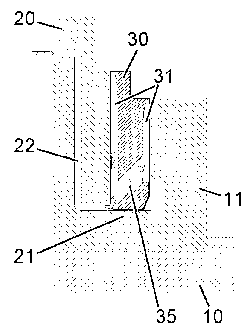
Figure 1 and Figure 2 show two embodiments of the hydrodynamic axial bearing
according to the invention, with the center of each of the figures showing a
section
along the shaft axis through the axial bearing. The axial bearing comprises a
floating disk 30 which is arranged axially between the bearing housing 20 and
the
bearing comb 11, which is arranged on the shaft 10 and rotates with the shaft.
Optionally, the bearing comb may be integrated in the shaft as a radially
protruding
projection, resulting in the floating disk being arranged axially between the
bearing
housing and the shaft projection. The left-hand and right-hand areas of each
of the
figures show a view of the floating disk from the respective side. The left-
hand side
shows the floating disk 30A viewed in the direction A, and the right-hand side
shows
the floating disk 30B viewed in the direction B.
The profiled annular surface of the floating disk 30A facing the bearing
housing
rotates at the absolute speed Vs, that is to say in the counterclockwise
direction
when viewed in the direction A in the illustrated embodiment. In this case,
the
lubricating oil which is introduced radially via lubricating grooves 31 into
the area of
the profiled annular
CA 02699711 2010-03-17
surface of the floating disk between the floating disk 30 and the bearing
housing 20, as
indicated by the broad arrows, is drawn into the wedge surfaces 32 in the
opposite
direction to the rotation direction of the floating disk. The pressure
required for the
supporting capability of the axial bearing is built up by the narrowing of the
lubricating
5 gap between the wedge surfaces 32 and the opposite smooth sliding surface on
the
bearing housing. The greatest pressure results in the area of the transition
from the
wedge surface 32 to the latching surface 33.
The profiled annular surface of the floating disk 30B facing the bearing comb
rotates at
the absolute speed vs, in the clockwise direction when viewed in the direction
B in the
illustrated embodiment. However, since the bearing comb 11 rotates in the same
direction at more than twice the speed vw, this results in a relative speed of
the profiled
annular surface vR, which runs counterclockwise, when considered in the
direction B.
The relative speed vR is in this case greater than the absolute speed V. Once
again,
the broad arrows indicate how the lubricating oil is carried radially outward
via the
lubricating grooves, and in the process is drawn into the wedge surfaces in
the
circumferential direction.
In the embodiment shown in Figure 1, the floating disk 30 has a radial step,
as a result
of which the side facing the bearing housing 20 projects in the radial
direction beyond
the side facing the bearing comb 11. The radial extents of the two sides of
the floating
disk are therefore different. The profiled annular surface on the side facing
the bearing
housing has an annular width r0 which is greater than the annular width rw of
the
annular surface on the side of the floating disk facing the bearing comb.
Because of the higher relative speed with which the wedge surfaces of the
profiled
annular surface rotate along the smooth sliding surface on the bearing comb on
the side
of the floating disk facing the bearing comb, a lubricating gap is formed,
despite the
smaller supporting area, which corresponds to that between the bearing housing
and
the side of the floating disk facing the bearing housing.
In the embodiment shown in Figure 2, the floating disk 30 has two sides of
equal size,
but whose profiled annular surfaces are different. The profiled annular
surface is
subdivided into a plurality of segments 34, wherein one segment comprises a
lubricating
groove 31, a wedge surface 32 and an adjacent latching surface 33. The annular
surface, which rotates more slowly in comparison to the stationary bearing
housing, on
CA 02699711 2010-03-17
6
the left-hand side has a greater number of segments 34 than the annular
surface, which
rotates at a higher relative speed, on the side facing the bearing comb.
The supporting capability can optionally be varied for example by varying the
inclination
angle of the wedge surface, thus making the area of the greatest supporting
force
smaller or larger. The transition between the wedge surface 32 and the
latching surface
33 may be provided by means of an edge, or as a continuously running surface
without
an edge. In the latter case, there is no need for any difference between the
wedge
surface and the latching surface, as a result of which, for example, the wedge
surface
can also rise continuously, at an angle which becomes continually smaller, as
far as the
next lubricating groove.
In the embodiment shown in Figure 3, the floating disk 30 once again has a
radial step,
as a result of which the side facing the bearing housing 20 projects in the
radial
direction beyond the side facing the bearing comb 11. In addition, an incline
is applied
on the radially inner side of the side facing the bearing comb, and the
internal radius of
the profiled annular surface is enlarged somewhat outward. The inner edge of
the
smooth sliding surface on the bearing comb is offset radially outward, thus
additionally
reducing the supporting area of the lubricating gap between the floating disk
30 and the
bearing comb 11, in comparison to the first embodiment.
Both sides of a floating disk for a hydrodynamic axial bearing must be
supplied with
lubricating oil. According to the invention, at least one supply hole 35 is
incorporated in
the floating disk for this purpose. The supply hole 35 connects the two sides
of the
floating disk, and allows lubricating oil to be supplied from one side to the
other.
Optionally, the floating disk has a supply hole for each lubricating groove on
the side
facing the bearing comb.
In the illustrated embodiment, the lubricating oil is passed via a lubricating
oil supply line
22 in the bearing housing into the area of the lubricating gap between the
floating disk
and the bearing housing 20. The rotation of the profiled annular surface feeds
the
lubricating oil along the lubricating grooves 31 radially outward, and in the
process
draws it into the wedge surfaces in the circumferential direction. The
lubricating oil is
30 also fed via the supply holes 35, which are arranged in the area of the
lubricating
grooves 31, into the area of the lubricating gap between the floating disk 30
and the
bearing comb 11. If, in this case, starting from the lubricating gap, the
supply holes with
CA 02699711 2010-03-17
7
the lubricating-oil supply are directed at an angle toward the outer edge,
rather than in
the axial direction, the lubricating-oil flow is assisted by the rotation of
the floating disk.
The supply hole means that there is very largely no need for any supply
grooves in the
area of the radial bearing of the floating disk. This reduces the lubricating-
oil throughput
through the decoupling gap between the bearing comb 11 and the bearing collar
21,
which is present when the floating disk 30 is borne on the stationary bearing
housing.
This is particularly advantageous when the decoupling gap leads into the
injection-oil
area, for example of the exhaust-gas turbocharger, in the area of the radial
bearing of
the floating disk, without any additional sealing element.
CA 02699711 2010-03-17
8
List of Reference Symbols
Shaft
11 Bearing comb
Bearing housing
21 Bearing collar
22 Lubricating oil supply line
Floating disk
30A Floating disk, bearing housing side (viewed in direction A)
30B Floating disk, bearing comb side (viewed in direction B)
31 Lubricating groove
32 Wedge surface
33 Latching surface
34 Segment of the profiled annular surface
Supply hole
rc Annular width on the side of the bearing housing
rw Annular width on the side of the bearing comb
VR Relative speed of the floating disk with respect to the bearing comb
vs Speed of the floating disk
vw Speed of the bearing comb