Note: Descriptions are shown in the official language in which they were submitted.
CA 02699816 2010-04-12
TITLE: SPILL CURTAILING TOOL
FIELD OF THE INVENTION
This invention pertains to hand tools for sealing a perforation in a fluid
reservoir to quickly curtail a spill from that reservoir, and more
particularly, it pertains to hand tools for inserting and inflating a bladder
in
a perforation through the wall of a fluid reservoir for temporary sealing the
perforation.
BACKGROUND OF THE INVENTION
Perforation plugging devices are well known in the marine industry
especially for making emergency repairs to the hulls of floating vessels.
Perforation and breach plugging devices are also used for quickly plugging
holes in containers of hazardous materials.
The following examples of breach plugging devices provide a good
sampling of the inventory of plugging tools available in the prior art;
US Patent 1,301,204 issued to P. C. Warner et al. on April 22, 1919;
US Patent 2,446,190 issued to C.A. Oding on August 3, 1948;
US Patent 3,866,560 issued to J. Steward on February 18, 1975;
US Patent 4,012,822 issued to J. J. Vrolyk et al. on March 22, 1977;
US Patent 4,329,132 issued to R.W. Melvold et al. on May 11, 1982;
US Patent 4,390,333 issued to M. A. J. Dubois on June 28, 1983;
US Patent 4,892,219 issued to R.W. Smith on January 9, 1990;
US Patent 5,245,941 issued to P. Gattuso on September 21, 1993;
US Patent 6,058,870 issued to J. E. Conley on May 9, 2000;
US Patent 6,467,421 issued to J. E. Conley on October 22, 2002;
1
CA 02699816 2010-04-12
US Patent 6,543,486 issued to J. H. Morris on April 8, 2003;
US Patent 6,722,304 issued to J.E. Conley on April 20, 2004;
DE Patent 019618761, filed by U. Schleicher, published on Nov. 12,1997;
GB Patent Appl. WO 01/16518, filed by A. Harris, publ. on Mar. 8,200 1;
CA Patent Appl. 2,040,214, filed by G.W. Kassbaum, publ. Oct. 12,199 1;
Canadian Patent 1,103,534, issued to C.J. Hsu on June 23, 1981.
Most hazardous spills occurring inland are from transport trucks involved
in highway accidents and railroad cars involved in derailments. In spite of
the work that has been done in the past to develop breach plugging devices
for floating vessels and large stationary tanks, it is believed that the
trucking industry still does not have a practical tool that can be carried in
a truck's tool box and that can be easily handled without much training to
stop a spill from a damaged tanker truck.
It is also believed that there is a need in the trucking industry for a tool
capable of stopping a spill without exposing the user of the tool to the
material escaping from a damage tanker. Because the tools of the prior art
require a direct approach to a breach in a reservoir, these tools are not
considered safe for use by handlers working under the stresses associated
with the urgency of these situations
The reservoir on a tanker truck has a relatively thin wall as compared to the
hull of a floating vessel. When a reservoir on a tanker truck is punctured by
accident, the edges of the hole are relatively thin and sharp, which make it
difficult to introduce and to inflate a bladder in that hole without damaging
the bladder. The tools of the prior art use rubber bladders which are not
practical for plugging holes in a thin metal shell, because a rubber bladder
is susceptible of rupturing before it is fully inflated.
2
CA 02699816 2010-04-12
It is for these reasons primarily, that an efficient tool has not yet been
introduced to the trucking industry for plugging thin shell reservoirs.
Therefore, it is believed that there is a need in the trucking industry in
particular, and by environment protection agencies for a hand tool that is
particularly useful to prevent hazardous spills and environmentally
sensitive spills from ruptured tanker trucks, ruptured railway cars, an other
reservoirs of that nature.
SUMMARY OF THE INVENTION
The word "fluid" is used herein to designate material in liquid form,
gaseous form or fluid-like substances such as powders, sand and grains.
In a first aspect of the present invention, there is provided a spill
curtailing
tool that has an elongated expandable frame; a first handle on a first end of
the frame; a second handle mounted to an intermediate position along the
frame; and a tube mounted to a second end of the elongated frame. The
second end of the frame supporting the tube is movable toward and away
from the first and second handles.
A pair of pressurized instant-foam-producing tanks are mounted to the
elongated frame between the first and second handles. The word "tank" is
used herein to designate, a cylinder, a canister or a reservoir of some type
filed with commercially available instant foam. The tanks are connected
to the tube by means of hoses for delivering instant foam through the tube.
A folded bladder is mounted over the tube for receiving instant foam
therein. The tube is angularly movable relative to a plane of the elongated
frame, as seen in the accompanying drawings, such that it can be pointed
in different directions relative to the plane of the elongated frame.
3
CA 02699816 2010-04-12
The principal advantages ofthe spill curtailing tool according to the present
invention are that the tool is portable and it is workable from an offset
position relative to a spill to be sealed whereby the user thereof is not
exposed to the spray of the spill.
In another aspect of the present invention, the spill curtailing tool has
hoses
connecting the pressurized foam-producing tanks to the tube. The tool also
has a tandem valve mounted along the hoses for selectively opening the
hoses. In this aspect of the invention, the tandem valve is mounted to the
second handle, and the second handle is mounted in a movable manner
along the intermediate portion of the frame.
The expression "tandem valve" is used herein to designate any flow control
mechanism capable of controlling the flow in a pair of hoses
simultaneously.
In yet another aspect of the present invention, the tube has spaced-apart
holes along a length thereof. The spill curtailing tool has an angularly
movable crosspiece mounted to the second end of the frame, and the tube
is mounted to the crosspiece such that it is angularly movable with the
crosspiece.
In yet a further aspect of the present invention, the spill curtailing tool
has
a pair of depth gauges mounted to the crosspiece on each side of the tube
respectively. These depth gauges are telescopically extendable, and are
preferably pressure sensitive.
Industrial applications for this tool comprises uses in the trucking industry,
firefighters equipments, emergency rescue organizations and environment
protection agencies. And of course, it can be used in the marine industry
4
CA 02699816 2010-04-12
or navies for stopping sea going boats and vessels from sinking. Yet
another industrial application is for plugging damaged pipelines containing
liquids or gases.
This brief summary has been provided so that the nature of the invention
may be understood quickly. A more complete understanding of the
invention can be obtained by reference to the following detailed description
of the preferred embodiment thereof in connection with the attached
drawings.
BRIEF DESCRIPTION OF THE DRAWINGS
A preferred embodiment of the present invention is illustrated in the
accompanying drawings, in which like numerals denote like parts
throughout the several views, and in which:
FIG. 1 illustrates a typical hazardous spill of fuel from an overturned
tanker truck, and a preferred mode of handling the preferred spill
curtailing tool;
FIG. 2 is a perspective view of the spill curtailing tool in a collapsed
mode;
FIG. 3 is a perspective view of the spill curtailing tool in an extended
mode;
FIG. 4 is a partial perspective view of the preferred spill curtailing tool
with the bladder-support tube extending at right angle from a plane
of the tool;
5
CA 02699816 2010-04-12
FIG. 5 is a perspective side view of the tube supporting a bladder in the
preferred tool;
FIG. 6 is a side view of a bladder mounted in a breach in a container;
FIG. 7 is a see-through view through the bladder of the preferred tool,
showing the tube of the tool extending through the breach
mentioned above.
DETAILED DESCRIPTION OF THE PREFERRED EMBODIMENT
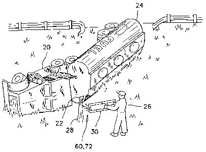
Referring back to FIG. 1, there is illustrated therein, an overturned tanker
truck 20, having a perforation 22 in the front side of its tank 24. The truck
operator 26 or other emergency-response personnel such as a fireman is
about to plug this perforation 22 to stop the spill 28 of fluid from the
perforation, using the preferred spill curtaining tool 30. FIG. 1 in
particular shows a preferred mode of handling the preferred spill curtailing
tool 30 such that the operator 26 is out of harms way from the spill 28.
The preferred spill curtailing tool 30 is illustrated in greater details and
in
a collapsed and stowed mode in FIG. 2. The tool 30 has a rectangular
telescopically extendable frame 32 having a non-extendable end 34 and an
extendable end 36. Both sides of the frame 32, at least along the
extendable end 36 are made of telescoping tubes 38.
The non-extendable end 34 of the frame 32 has a first handle 40 at a far end
thereof, and a second handle 42 mounted at an intermediate position there
along. The extendable frame 32 has a rectangular shape and lies and
extends in a plane. The second handle 42 is adjustable along the extendable
6
CA 02699816 2010-04-12
portion of the frame 36, as illustrated by arrow 44 such that an operator
using the preferred tool can work at ease with the preferred tool.
The extendable portion 36 of the frame 32 can be locked in position at a
certain length by means of hand nuts 46 having a knurled surface for
example. The handles 40, 42 may also have knurled surfaces to offer a
better hand grip.
Although the preferred embodiment has knurled nuts 46 to retain the
extendable portion 36 of the preferred tool 30 to a proper position, other
locking devices can be used. For example, there are friction-type; wedge-
type; set-screw type and cam-lock type locking mechanisms available
commercially, which would work as well in the preferred tool 30.
Although a telescoping frame has been illustrated herein, it will be
appreciated that a folding frame may also be used to obtain basically the
same result for extending and shortening the preferred tool.
Attached to the frame 32 between the two handles 40, 42, or to the two
handles 40, 42, there are mounted two tanks 48 containing cooperatively
a two-part instant foaming agent under pressure. The two-part foaming
agent such as polyurethane or other commercially available instant foam is
well known in the art and therefore no further explanation is deemed
required.
In the preferred embodiment, a tandem valve 50 is mounted to the second
handle 42 and is operated by a lever 52. The tanks 48 are connected by
hoses 54 to the valve 50.
7
CA 02699816 2010-04-12
An elongated, hollow, cylindrical bladder-support tube 60 is mounted to the
extendable portion 36 of the frame 32. The foaming agent from the two
tanks 48 is delivered to the hollow bladder-support tube 60 via hoses 62
and through a static mixing chamber 64.
Upon the length of the tube 60 there is mounted an inflatable bladder 66,
which is illustrated in FIG. 5 in a collapsed, folded mode. The folded
bladder 66 is adapted to receive and to be inflated by the instant foam
delivered from the tanks 48.
The static mixing chamber 64 is mounted at the base of the bladder 66, to
ensure proper mixing of the foaming agent prior to reaching the bladder 66.
It will be appreciated that the bladder 66 may be wrapped tight inside an
envelope that can be ripped off by the pressure of the foam filling the
bladder. It will also be appreciated that the tube 60 is removably mounted
to the static mixing chamber 64 such that the tube and the bladder are easily
replaced after one use.
The tube 60 has spaced apart holes 68 along its length for distributing the
foaming agent inside the full length of the bladder 66 and on both sides of
a breach to be sealed.
Referring back to FIGS. 2 - 4, the base of the bladder-support tube 60 is
mounted on a movable crosspiece 70. The movable crosspiece 70 lies in
the same plane as the frame 32, and is articulated about an axis that is
parallel to handles 40, 42. Because the bladder-support tube 60 is mounted
to the crosspiece 70, the bladder-support tube 60 can be oriented angularly
relative to the plane of the frame 32, as can be seen in FIG. 4.
8
CA 02699816 2010-04-12
On both sides of the bladder-support tube 60, there are provided two
telescoping depth gauges 72 extending from the crosspiece 70. Both depth
gauges 72 extend parallel to the bladder-support tube 60 and are movable
about the crosspiece 70 in unison with the bladder-support tube 60.
The purpose of the depth gauges 72 is to support the bladder 66 from both
sides of a breach to be sealed, at a proper depth in that breach. The depth
gauges 72 are preferably telescopically extendable and spring loaded so that
a user of the preferred tool can apply a slight pressure on the preferred tool
against a breach to be sealed, and feel a bottoming of the depth gauges 72
before pulling the lever 52 on the tandem valve 50 and filling the bladder
66 with instant foam. The pressure responsive feature on the depth gauges
72 can also be effected by other devices than springs. Therefore, the
expression "spring loaded" should be understood as encompassing, air-type
shock absorbers, oil-type shock absorbers, elastic bumpers and devices of
that nature.
It will be appreciated that when the bladder-support tube 60 is pointing
away from the plane of the tool 30, such as illustrated in FIG. 4, it is
relatively easy for a fireman for example to extend the bladder-support tube
60 into a perforation 22 and into a spill in progress, while standing aside or
offset from the direction of the flow, as illustrated in FIG. 1 for example.
This is particularly useful for plugging a hole and curtailing a spill without
being exposed to the splash of the spill.
The ability to adjust the orientation of the bladder-support tube 60 relative
to the plane of the tool 30 is also advantageous for introducing a plugging
bladder in a work area that has a tight clearance for moving the tool or in
a hole that is impossible to reach in a direct approach mode.
9
CA 02699816 2010-04-12
Yet another advantage of the preferred tool is that a boat operator can reach
a breach in the hull of his boat that would be below the waterline, by
extending the preferred tool to its full extension alongside the boat's hull,
adjusting the tube into the breach and sealing the leak. It also can be
deployed under water at depths by a diver.
FIG. 6 represents a bladder 66 that has been installed and inflated in a
breach 80 in a container. The view is taken with the container seen in a
cross-section mode. The view in FIG. 7 is a see-through view of the
breach 80 being sealed by an expanding bladder 66. The view is taken
from the inside of the container being sealed.
As it was mentioned before, the wall of a reservoir on a highway tanker has
a relatively thin wall, and a breach in this reservoir has sharp points 82 and
narrow crevices 84. When a bladder 66 is inflated in this hole 80 the
material of the bladder must be able to slide over the sharp points 82
without catching and tearing. The material of the bladder must be able to
slide and stretch over the sharp points 82 and to freely deploy to fill the
crevices 84.
In order to fulfill these needs and requirements, a preferred material of
construction for the bladder 66 is a lamination of multiple layers of
polymeric materials, such as MYLARTM alone or a combination of
MYLARTM and KEVLARTM. Both materials are manufactured by Dupont
Inc.