Language selection

Search

Patent 2699831 Summary

Third-party information liability

Some of the information on this Web page has been provided by external sources. The Government of Canada is not responsible for the accuracy, reliability or currency of the information supplied by external sources. Users wishing to rely upon this information should consult directly with the source of the information. Content provided by external sources is not subject to official languages, privacy and accessibility requirements.

Claims and Abstract availability

Any discrepancies in the text and image of the Claims and Abstract are due to differing posting times. Text of the Claims and Abstract are posted:

  • At the time the application is open to public inspection;
  • At the time of issue of the patent (grant).
(12) Patent Application: (11) CA 2699831
(54) English Title: APPARATUS AND ASSOCIATED METHODS TO GENERATE USEABLE ENERGY
(54) French Title: APPAREIL ET PROCEDES ASSOCIES POUR GENERER UNE ENERGIE UTILISABLE
Status: Deemed Abandoned and Beyond the Period of Reinstatement - Pending Response to Notice of Disregarded Communication
Bibliographic Data
(51) International Patent Classification (IPC):
  • F03B 07/00 (2006.01)
  • F03B 09/00 (2006.01)
  • F03B 17/02 (2006.01)
(72) Inventors :
  • BASTOS RIBEIRO, RENATO (Brazil)
(73) Owners :
  • RENATO BASTOS RIBEIRO
(71) Applicants :
  • RENATO BASTOS RIBEIRO (Brazil)
(74) Agent: ROBIC AGENCE PI S.E.C./ROBIC IP AGENCY LP
(74) Associate agent:
(45) Issued:
(86) PCT Filing Date: 2008-10-03
(87) Open to Public Inspection: 2009-04-09
Availability of licence: N/A
Dedicated to the Public: N/A
(25) Language of filing: English

Patent Cooperation Treaty (PCT): Yes
(86) PCT Filing Number: PCT/IB2008/054063
(87) International Publication Number: IB2008054063
(85) National Entry: 2010-03-16

(30) Application Priority Data:
Application No. Country/Territory Date
12/107,913 (United States of America) 2008-04-23
12/239,159 (United States of America) 2008-09-26
60/978,060 (United States of America) 2007-10-05

Abstracts

English Abstract


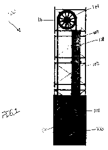
The present disclosure relates to an apparatus and
associated methods for generating energy by capturing and taking benefit
of the energy generated by any quantity of air surfacing inside water.
The apparatus includes a frame structure (102) to which is rotatably
mounted an upper drive wheel (104), a lower wheel (106), and a
vertical fluid column container (108). An endless chain (110) of gas
capsule elements (112) is mounted on the upper and lower wheels
(106, 108). This endless chain (110) passes vertically up into and
through the fluid column container (108) through a seal port (118) in
the bottom of the container (108). As the endless chain (110) of gas
capsule elements (102) passes vertically through the fluid (109) in
the container (108), fluid pressure on the elements (110) due to the
height of the column of fluid in the container (108) produces a net
bouyant force upward on the elements (112), causing them to rise,
generating kinetic energy that turns the wheels (106,108).


French Abstract

La présente invention porte sur un appareil et sur des procédés associés pour générer de l'énergie par capture et exploitation de l'énergie générée par une quelconque quantité d'air au-dessus d'une eau intérieure. L'appareil comprend une structure de cadre sur laquelle est montée à rotation une roue motrice supérieure, une roue inférieure et un conteneur en colonne pour fluide vertical. Une chaîne sans fin d'éléments de capsule de gaz est montée sur les roues supérieure et inférieure. Cette chaîne sans fin passe verticalement dans et à travers le conteneur en colonne pour fluide à travers un orifice d'étanchéité dans la partie inférieure du conteneur. A mesure que la chaîne sans fin d'éléments de capsule de gaz passe verticalement à travers le flux dans le conteneur, la pression de fluide sur les éléments due à la hauteur de la colonne de fluide dans le conteneur produit une force de flottabilité nette dirigée vers le haut sur les éléments, les amenant à se soulever, générant de l'énergie cinétique qui fait tourner les roues.

Claims

Note: Claims are shown in the official language in which they were submitted.


7
CLAIMS
1. A method of generating useable kinetic energy comprising:
introducing at least one gas containing capsule element into a liquid
medium below a surface of the liquid medium, wherein the element is connected
to a
wheel outside the liquid medium;
allowing the capsule element in the liquid medium to rise through the
medium to the surface; and
passing the element out of the medium and over the wheel; and
returning the capsule element to the liquid medium below the surface of
the medium.
2. The method of claim 1 further comprising providing a container for the
liquid medium having a closed bottom and an endless chain of gas containing
capsule
elements passing into the bottom of the container.
3. The method of claim 2 further comprising providing a second wheel over
which the endless chain of elements pass.
4. The method of claim 3 wherein returning the capsule element comprises
passing the capsule elements through a port in the bottom of the container.
5. The method of claim 2 further comprising sealing the port in the bottom of
the container around the capsule elements as the elements pass through the
port into
the container.
6. An apparatus for generating useable kinetic energy comprising:
a structural frame;
a generally vertical fluid container containing a fluid supported on the
frame;
an endless chain of gas containing capsule elements having a portion of the
elements passing through the fluid in the fluid container;
a wheel rotatably fastened to the frame outside the container, the endless
chain
of elements passing over the wheel, whereby buoyant forces on the capsule
elements

8
in the fluid cause the elements to rise generally vertically through and out
of the fluid
and then around the wheel to thereby rotate the wheel.
7. The apparatus of claim 6 wherein the wheel is rotatably mounted above
the container.
8. The apparatus of claim 7 further comprising a second wheel rotatably
mounted below the container over which the endless chain of elements pass.
9. The apparatus of claim 7 wherein the fluid container has a bottom
configured with a port receiving and passing the capsule elements therethrough
into the
container.
10. The apparatus of claim 9 wherein the port includes a sealing glove to
prevent fluid leakage from the container while permitting passage of the
capsule
elements onto the container.
11. The apparatus of claim 9 wherein the sealing glove has at least one O-ring
seal around the port and around each capsule element as it passes through the
port.
12. A kinetic energy generation apparatus comprising:
a frame;
an elongated fluid container containing a fluid vertically mounted on the
frame,
the fluid container having a bottom and a port through the bottom;
an upper wheel rotatably mounted to the frame above the container;
a lower wheel rotatably mounted to the frame below the container; and
an endless chain of spaced gas containing capsule passing into the container
through the port, through the fluid in the container, and out of a top of the
container,
around a portion of the upper wheel and around a portion of the lower wheel
and
returning to the port through the bottom of the container, whereby buoyant
forces of the
fluid on the capsule elements cause them to move upward through the fluid
thereby
causing movement of the endless chain over the wheels generating rotational
kinetic
energy in the wheels.

9
13. The apparatus of claim 12 wherein each capsule element comprises:
a hollow tubular wall;
a curved top cap closing an upper end of the tubular wall;
a bottom cap closing a bottom end of the tubular wall; and
a linkage pin supported in the bottom cap engaging a portion of an adjacent
element.
14. The apparatus of claim 13 wherein the top cap has a tongue member
axially protruding therefrom.
15. The apparatus of claim 14 wherein each linkage pin engages with the
tongue member of an adjacent capsule element.
16. The apparatus of claim 13 wherein the bottom cap has a curved shape
complementary to the curved top cap of an adjacent capsule element.
17. The apparatus of claim 16 wherein the bottom cap further has a central
slot through which the linkage pin passes engaging the portion of an adjacent
element.
18. The apparatus of claim 17 wherein the portion of the adjacent element is a
tongue member axially protruding from the curved top cap of the adjacent
capsule
element.
19. The apparatus of claim 12 wherein the port through the bottom of the
container includes a sealing glove receiving the capsule elements
therethrough.
20. The apparatus of claim 19 wherein the sealing glove includes one or more
seals to prevent fluid from passing out of the container while the capsule
element enters
the container.

Description

Note: Descriptions are shown in the official language in which they were submitted.


CA 02699831 2010-03-16
WO 2009/044377 PCT/IB2008/054063
1
APPARATUS AND ASSOCIATED METHODS TO
GENERATE USEABLE ENERGY
BACKGROUND
1. Field
[0001] The present disclosure is related to the generation of electrical
energy, and
more particularly the conversion of kinetic energy in rising air bubbles
through water into
usable electrical energy.
2. General8ackground
[0002] Energy costs and concerns have highlighted the need for alternative and
renewable energy sources. Recent research into different methods of producing
energy
involving the traditional uses of wind, water, and solar energy has been
widespread,
This reflects the major threats of climate change due to pollution, exhaustion
of fossil
fuels, and the environmental, social and political risks of fossil fuels.
[0003] One potential source of renewable energy is the kinetic energy created
by
rising air in water. Air rises in water because it is less dense than water,
meaning that a
given volume of air weighs less than the same volume of water. Water is nearly
1,000
times denser than air. Any object or substance that weighs less than the
amount of fluid
it displaces will float on that fluid.
[0004] Buoyancy is the upward force on an object produced by the surrounding
fluid
(i.e., a liquid or a gas) in which it is fully or partially immersed, due to
the pressure
difference of the fluid between the top and bottom of the object. The net
upward
buoyancy force is equal to the magnitude of the weight of fluid displaced by
the body.
This net force enables the object to float or at least to seem lighter.
[0005] Buoyancy provides an upward force on the object. The magnitude of this
force
is equal to the weight of the displaced fluid. The buoyancy of an object
depends,
therefore, only upon two factors: the object's volume, and the density of the
surrounding
fluid. The greater the object's volume and surrounding density of the fluid,
the more
buoyant force it will experience. If the buoyancy of an unrestrained and
unpowered

CA 02699831 2010-03-16
WO 2009/044377 PCT/IB2008/054063
2
object exceeds its weight, it will tend to rise. An object whose weight
exceeds its
buoyancy will tend to sink. This buoyant force on air bubbles in water causes
the air
bubbles to rise to the surface.
SUMMARY
[0006] In one aspect of the present disclosure, a method and apparatus for
generating
energy is disclosed. The basic method comprises first introducing a void space
such as
air into fluid below the surface of the fluid by capturing air in an enclosed
tubular
capsule element that is introduced beneath the water surface. This capsule is
then
forced upward by buoyant forces of the fluid on the capsule. Then the capsules
in the
fluid are allowed to rise to the surface. To generate energy, the kinetic
energy in the
upwardly moving and subsequently surfacing capsule elements is captured and
converted into a useable form of energy.
[0007] In a further aspect of the present disclosure, an apparatus generating
usable
energy from the air or other gas enclosed in a chain of capsule elements and
introduced
into a column of water or other fluid is disclosed. The apparatus may
preferably include
a vertical tank filled with a fluid medium. Through this fluid medium a series
of capsule
elements, linked together in an endless chain, are introduced, one by one,
through a
sealed entry port at the bottom of the fluid column. The buoyant forces on the
capsule
elements drive the chain of elements upward through the fluid column. The
endless
chain of elements exits the top of the column and passes over an upper wheel
and then
around a lower wheel and back into the entry port at the bottom of the tank.
[0008] Finally, a generator is attached to the energy conversion axle to
convert the
kinetic energy of the moving elements into usable energy. In exemplary
embodiments,
the energy conversion mechanism comprises a vertical fluid column, a pair of
upper and
lower gear or pulley wheels outside the fluid column, an endless chain of
airtight
capsule elements extending between the wheels and capable of rotating the
wheels;
and a generator communicating with one of the wheels, wherein the capsule
elements
pass vertically through the fluid column via a fluid tight port at the bottom
of the column.
The capsule elements displace the fluid, resulting in an upward buoyancy force
being

CA 02699831 2010-03-16
WO 2009/044377 PCT/IB2008/054063
3
exerted on the endless chain of elements, causing upward movement of the
elements,
thus turning the wheels to rotate a generator rotor to produce useable
electrical energy.
DRAWINGS
[0009] The foregoing aspects and advantages of the present disclosure will
become
more readily apparent and understood with reference to the following detailed
description, when taken in conjunction with the accompanying drawings,
wherein:
[0010] Figure 1 is a side view of an apparatus in accordance with an
embodiment of
the present disclosure.
[0011] Figure 2 is a side view of the lower portion of the apparatus in Figure
1.
[0012] Figure 3 is a separate side view of two pairs of capsule elements
utilized in the
endless chain of elements shown in the apparatus of Figure 1.
[0013] Figure 4 is a sectional view of the capsule elements shown in Figure 3.
DETAILED DESCRIPTION
[0014] Turning now to the drawings, Figure 1 is a side view of one embodiment
100 of
an apparatus according to the present disclosure. The apparatus 100 includes a
frame
structure 102 to which is rotatably mounted an upper drive wheel 104, a lower
wheel
106, and a vertical fluid column container 108. An endless chain 110 of air
capsule
elements 112 is mounted on the upper and lower wheels 104 and 106. This
endless
chain 110 passes vertically up into and through the fluid column container 108
through a
seal port 114 in the bottom of the container 108.
[0015] As the endless chain 110 of air capsule elements 112 passes vertically
through
the fluid 109 in the container 108, fluid pressure on the elements 112 due to
the height
of the column of fluid 109 in the container 108 produces a net buoyant force
upward on
the elements 112, causing them to rise. The rising elements 112 are connected
together such that this motion causes the upper and lower wheels 106 and 108
to turn.
An electrical generator (not shown), can be attached to at least one of the
axles 116 of
the wheels 106 and 108 to convert the kinetic energy of the rotating wheels
106 and

CA 02699831 2010-03-16
WO 2009/044377 PCT/IB2008/054063
4
108 to electrical energy. Alternatively, the rotating wheels can directly
provide the
motive power to other devices in a well known manner to those skilled in the
art.
[0016] This endless chain 110 of capsule elements 112 is introduced at the
bottom, or
inferior, part, of the container 108. The chain 110 passes through an entrance
seal or
glove 118 that has one or more low friction seal ring members 120 that prevent
leakage
of fluid out of the container 108, while minimizing the restraining or
resistive forces
being applied to each of the capsule elements 112.
[0017] Referring now to Figure 2, the net energy creation generated by the
apparatus
100 includes primarily the difference between the energy produced by the
buoyancy
forces on the air capsule elements in the fluid and the energy consumed by the
chain
friction as it passes through the entrance glove 118. Preferably this entrance
glove 118
has two spaced seals 120 so that as an upper element 112 in the glove 118
passes
from the glove into the container 108 the lower seal ring 120 prevents fluid
leakage.
The glove 118 is preferably preceded by a set of guide rollers 119 mounted
beneath the
glove 118. A single seal ring 120 may also be utilized in alternative
configurations.
Such a seal ring 120 may be an 0-ring made of a rubber such as a silicon
rubber or
other suitable material that is compatible with the fluid 109 in the container
108.
[0018] Referring now to Figures 3 and 4, each of the capsule elements 112 has
a
hollow tubular wall 122 having a curved upper end cap 124. Extending axially
from the
end cap 124 is a linkage tongue 126 that has a hole 128 therethrough. The
curve of the
upper end cap is a radial curve centered on the hole 128. Closing the opposite
end of
the tubular wall 122 is a bottom end cap 130. The bottom end cap 130 has a
curved
end surface complementary to that of the upper end cap 124 and has a central
axial
blind slot leading to a pivot pin 132. This pivot pin 132 is fixed to the
bottom end cap
130 and passes through the hole 128 in the linkage tongue 126 in the next
element 112
in the chain 110. There is a small gap 134 between the bottom end cap 130 of
each
element 112 and the connected top end cap 124 of the next element 112. This
permits
the fluid forces in the container 108 to be applied to the bottom of each
element 112 so
that a net positive buoyant force is exerted by the fluid in the container 108
on each
element 112 while the element 112 is in the container 108. As is shown in
Figure 4, the

CA 02699831 2010-03-16
WO 2009/044377 PCT/IB2008/054063
gap 134 includes open space within the bottom end cap 130 and the upper end
cap 124
that will be filled with the fluid 109.
[0019] Each wheel 104 and 106 is mounted on its axle 116 via low friction
bearings
such that frictional forces on the wheels is minimized. Each wheel 106 and 104
has a
peripheral rim shape that is complementary to that of the capsule elements
112.
Alternatively the periphery of the wheels 104 and 106 may have teeth or cogs
that
engage complementary recesses on the elements 112 such that the linear
movement of
the endless chain 110 of elements 112 up through the container 108 of fluid
109 is
efficiently imparted to rotation of the wheels 104 and 106.
[0020] Each of the capsule elements 112 is preferably made of a light plastic
or metal
material such as aluminum and may be coated with a low friction material such
as teflon
to minimize friction as it passes through the fluid 109 in the container 108.
[0021] The container 108 is preferably a right cylinder in shape and may have
a
rectangular, circular, or other cross sectional shape. The fluid 109 in the
container 108
may be water, mineral oil, or other liquid. The fluid 109 could also be a very
heavy
liquid such as mercury which would impart a tremendous buoyant force on each
capsule element 112 that passes into and upward through the fluid 109. The
frame 102
may be a metal structural frame that is open, as is shown in the Figures or
may be
closed to make a completely self contained structure. Further, the axles 116
are
bearing supported from the structural frame 102 and each may be linked by
conventional means to a motor or generator to make use of the kinetic energy
generated by the apparatus 100.
[0022] While the above description contains many particulars, these should not
be
considered limitations on the scope of the disclosure, but rather a
demonstration of
embodiments thereof. The process and methods disclosed herein include any
combination of the different species or embodiments disclosed. Accordingly, it
is not
intended that the scope of the disclosure in any way be limited by the above
description.
The various elements of the claims and claims themselves may be combined in
any

CA 02699831 2010-03-16
WO 2009/044377 PCT/IB2008/054063
6
combination, in accordance with the teachings of the present disclosure, which
includes
the claims.

Representative Drawing
A single figure which represents the drawing illustrating the invention.
Administrative Status

2024-08-01:As part of the Next Generation Patents (NGP) transition, the Canadian Patents Database (CPD) now contains a more detailed Event History, which replicates the Event Log of our new back-office solution.

Please note that "Inactive:" events refers to events no longer in use in our new back-office solution.

For a clearer understanding of the status of the application/patent presented on this page, the site Disclaimer , as well as the definitions for Patent , Event History , Maintenance Fee  and Payment History  should be consulted.

Event History

Description Date
Time Limit for Reversal Expired 2014-10-03
Application Not Reinstated by Deadline 2014-10-03
Deemed Abandoned - Failure to Respond to Maintenance Fee Notice 2013-10-03
Inactive: Abandon-RFE+Late fee unpaid-Correspondence sent 2013-10-03
Inactive: Correspondence - MF 2010-08-10
Inactive: Cover page published 2010-05-27
Inactive: Notice - National entry - No RFE 2010-05-13
Inactive: Inventor deleted 2010-05-13
Application Received - PCT 2010-05-13
Inactive: First IPC assigned 2010-05-13
Inactive: IPC assigned 2010-05-13
National Entry Requirements Determined Compliant 2010-03-16
Application Published (Open to Public Inspection) 2009-04-09

Abandonment History

Abandonment Date Reason Reinstatement Date
2013-10-03

Maintenance Fee

The last payment was received on 2012-09-14

Note : If the full payment has not been received on or before the date indicated, a further fee may be required which may be one of the following

  • the reinstatement fee;
  • the late payment fee; or
  • additional fee to reverse deemed expiry.

Patent fees are adjusted on the 1st of January every year. The amounts above are the current amounts if received by December 31 of the current year.
Please refer to the CIPO Patent Fees web page to see all current fee amounts.

Fee History

Fee Type Anniversary Year Due Date Paid Date
Basic national fee - standard 2010-03-16
MF (application, 2nd anniv.) - standard 02 2010-10-04 2010-06-16
MF (application, 3rd anniv.) - standard 03 2011-10-03 2011-10-03
MF (application, 4th anniv.) - standard 04 2012-10-03 2012-09-14
Owners on Record

Note: Records showing the ownership history in alphabetical order.

Current Owners on Record
RENATO BASTOS RIBEIRO
Past Owners on Record
None
Past Owners that do not appear in the "Owners on Record" listing will appear in other documentation within the application.
Documents

To view selected files, please enter reCAPTCHA code :


To view images, click a link in the Document Description column. To download the documents, select one or more checkboxes in the first column and then click the "Download Selected in PDF format (Zip Archive)" or the "Download Selected as Single PDF" button.

List of published and non-published patent-specific documents on the CPD .

If you have any difficulty accessing content, you can call the Client Service Centre at 1-866-997-1936 or send them an e-mail at CIPO Client Service Centre.


Document
Description 
Date
(yyyy-mm-dd) 
Number of pages   Size of Image (KB) 
Drawings 2010-03-15 3 950
Abstract 2010-03-15 2 80
Claims 2010-03-15 3 108
Description 2010-03-15 6 250
Representative drawing 2010-05-13 1 27
Notice of National Entry 2010-05-12 1 195
Reminder of maintenance fee due 2010-06-06 1 116
Reminder - Request for Examination 2013-06-03 1 118
Courtesy - Abandonment Letter (Request for Examination) 2013-11-27 1 164
Courtesy - Abandonment Letter (Maintenance Fee) 2013-11-27 1 172
PCT 2010-03-15 2 66
Fees 2010-06-15 1 52
Correspondence 2010-08-09 1 44
Fees 2011-10-02 1 50
Fees 2012-09-13 1 60