Note: Descriptions are shown in the official language in which they were submitted.
CA 02700101 2010-04-14
SIMULTANEOUS DISPLACEMENT DEVICE FOR SLIDING DOORS
Object of the invention
The present invention refers to a simultaneous displacement device for sliding
doors
comprising, both two sliding leaf which slide in the same direction and sense
and three
and four sliding leaves which slide in the opposite direction to the two first
leaves in a
synchronized manner. All the main elements which configure the device are
integrated
in an upper guide with easy installation and mounting.
The present invention is especially suitable for applying it in glass sliding
doors which
are manually run with respect to fixed enclosures or panels which frame an
open
passage area assisted by said door.
Background of the invention
There are known simultaneous displacement devices for sliding doors with only
two
sliding leaves, both with the ability to simultaneously move in the same
direction and
sense. To that end, the first sliding leaf is hung from an upper guide through
a couple
of moving carriages which slide inside it and from which there hang skids
integral to a
bearing profile holding said leaf. The second sliding leaf is hung in the same
way
through a second upper guide parallel to the first leaf. In order to carry out
the
simultaneous displacement of both leaves, the first one of them features a
cogged belt
arranged between two pulleys integral to the bearing profile. Each one of the
pulleys is
located at one of the side ends of the first sliding leaf, so that the belt
extends along the
whole width thereof. The belt is engaged at a fixed point of reference,
generally a part
anchored to the ceiling, next to the upper guides, while the second sliding
leaf is
engaged to said belt. In this way, when the sliding of the second sliding leaf
starts to
pull from the belt of the first leaf, which, as it is anchored to a fixed
point, in turn pulls
from one of the pulleys thus producing the simultaneous displacement of both
sliding
leaves.
The simultaneous displacement device described above has important limitations
and
inconveniences. The main limitation is that it only allows the simultaneous
sliding of two
sliding leaves running in the same direction and sense. That is, it does not
work with
CA 02700101 2010-04-14
-2-
sliding doors the leaves of which run in a synchronized manner in opposite
senses.
This limitation makes the device described above to be intended to a limited
number of
applications or uses. Specifically, for its application or use in sliding
doors which have a
relatively small free passage width. As regards the inconveniences, it is
noted the
mounting complexity of the device described above, since it implies both the
installation
of an upper guide for each one of the two sliding leaves and the installation
of the
anchoring part of the cogged belt, among other elements.
The present invention solves the problems described above in a fully
satisfactory
manner thanks to a device which has great application flexibility and
simplicity.
Specifically, the device of the present invention allows both the simultaneous
displacement of two sliding leaves moving in the same direction and sense, and
the
simultaneous sliding of three and four sliding leaves running in the opposite
sense to
that of the two first leaves in a synchronized manner. All main elements
configuring the
device are integrated in an upper guide with easy installation and mounting.
Description of the invention
In order to solve the aforementioned problems, the simultaneous displacement
device
for sliding doors of the present invention is integrated in an upper guide
from which
there are hung a first and second sliding leaves. Both sliding leaves have the
ability to
slide in the upper guide direction, thanks to the use of fastening clamps
having rolling
means which slide on tracks arranged inside said upper guide.
The device of the present invention comprises a first cogged belt enabled for
the union
of the first sliding leaf. The first cogged belt is established between the
first set of
cogged pulleys which rotate freely on a first axis and second axis
respectively, where
said first and second axes are integral to the upper guide. The device of the
present
invention also comprises a second cogged belt enabled for the union of the
second
sliding leaf and some clutching means. Preferably, the union of the sliding
leaves to the
cogged belts is carried out through the use of connection parts, which are
fixed at one
of their ends to clamps while at the other end they hold the belts.
The second cogged belt is established between a second set of cogged pulleys
which
rotate freely on the first axis and the second axes respectively.
CA 02700101 2010-04-14
-3-
In turn, the clutching means enable to adopt a first position where the first
cogged belt
and the second cogged belt move independently, and a second position where the
first
cogged belt and the second cogged belt move integrally.
The first position enables the first and second sliding leaves to move
separately. This
first position plays an important role during mounting and maintenance
operations.
Specifically, it enables to adjust the final position of the sliding doors,
once they are
fixed to the corresponding cogged belts, thus obtaining the desired
overlapping. Such
overlapping can be produced either between the sliding leaves themselves or
between
the sliding leaves and the enclosures or fixed panels where they are set.
The second position enables the first and second sliding leaves to run
simultaneously
in the same direction and sense; this sense which can be the sense
corresponding to
the door opening or the one corresponding to the closing of the door. The
displacement
speeds of the first and second sliding leaves adjust for each one of them
according to
the diameter of the first set of cogged pulleys and to the diameter of the
second set of
cogged pulleys respectively. Taking the example that the first sliding leaf is
the closest
to the final point and that its path is half the path of the second sliding
leaf, for both of
them to start and finish their displacement simultaneously it is necessary for
the second
one to move at twice the speed of the first. To that end, the pulleys of the
first set
present half the diameter of the pulleys of the second set. It is also
possible that there
exist other path relations between the first and second sliding leaves. In any
case, in
order to avoid undesired overlapping or gaps between leaves once the door is
open or
closed, it is necessary to adjust the sliding speed of each sliding leaf in a
correct
manner through the diameters of the first and second pulley sets.
There exist multiple solutions to clutch and unclutch the first and second
cogged belts,
which gives place to the first and second position respectively. However, the
clutching
means of the present invention preferably comprise a wheel which rotates
freely on
one of the axes and which has blocking means which enable to integrate their
movement with that of the cogged pulleys arranged in the same axis.
Preferably, the
wheel is comprised between two cogged pulleys of the same axis. The blocking
means
comprise one or more through holes coinciding with blocking holes drilled on
the
cogged pulleys, between which at least one through element is inserted, for
example, a
cotter pin, pin or screw, among other elements. In order to facilitate the
clutching or
CA 02700101 2010-04-14
-4-
unclutching of the device, the pulleys have multiple blocking holes forming a
circle
which is concentric to the pulley axis. Thus, with small rotations applied on
the pulleys
and on the cogwheel, the blocking holes are easily made to coincide with the
through
hole.
Additionally, the wheel comprises a continuous perimeter groove which engages
with
one or more protruding elements arranged on the pulleys of the first set or of
the
second set, without said engaging limiting the relative movement between the
wheel
and the corresponding pulley, that is, the protruding element slides freely
inside the
continuous perimeter groove. Likewise, the wheel also comprises one or more
discontinuous perimeter grooves, arranged on the opposite face of the
continuous
perimeter groove, which engage with the protruding elements of the pulleys of
the first
set or of the second set and which block the relative movement between the
wheel and
the corresponding pulley.
Additionally, the wheel also comprises one or more flexible protruding pivots,
the end of
which coincides with a plurality of holes arranged concentrically in the
pulleys of the
first set or of the second set. This enables to precisely face the blocking
means to
facilitate the insertion of the through element.
Preferably, the wheel also comprises a cogged profile.
The axes can be reinforced by reinforcement pieces which are joined to the
lower end
of the axis and which present a separating element which avoids the derailment
of the
second cogged belt.
The configuration of the previously described simultaneous displacement device
for
sliding doors is associated to a preferred embodiment, which is non-limiting
for the
present invention. However, it can be obviously concluded that the device of
the
present invention can be applied in sliding doors having more than two sliding
leaves,
where all of them have the ability to displace in the same direction and
sense. This is
attained adding, for each leaf additional to the second, a new cogged belt
established
between a new set of cogged pulleys which rotate freely on the first axis and
the
second axis respectively. At the same time, said pulleys are integrated
through
clutching means such as the one described. As in the preferred embodiment, the
CA 02700101 2010-04-14
-5-
displacement speeds of each sliding leaf are adjusted through diameters of
each set of
cogged pulleys.
According to a second preferred embodiment of the present invention, the
device
comprises a third cogged belt enabled to join a third sliding leaf, said third
cogged belt
is established between a third set of cogged pulleys which rotate freely on a
third and
fourth axes, respectively, where said third and fourth axes are integral to
the upper
guide, being the movement of the third cogged belt synchronized and opposite
to the
movement of the first cogged belt. Through this configuration, it is possible
for the first
and third sliding leaves to run in a synchronized manner in opposite senses
and
simultaneously together with the second sliding leaf.
In order to avoid the derailment of the first and third cogged belts, the
device of the
present invention comprises a bar integral to the upper guide, arranged in
front of the
first and third axes at the level of the first cogged belt and of the third
cogged belt.
Besides, the aforementioned reinforcement part is joined to the lower end of
the first
and third axes to provide stiffness to both axes and absorb efforts thereon,
ensuring
that the gear mechanism enabling the synchronism is maintained at all times.
According to a third preferred embodiment of the present invention, the device
also
comprises a fourth cogged belt enabled to join a fourth sliding leaf and
second
clutching means.
The fourth cogged belt is established between a fourth set of cogged pulleys
which
rotate freely on the third axis and the fourth axis respectively.
In turn, the second clutching means enable to adopt a third position where the
third
cogged belt and the fourth cogged belt move independently, and a fourth
position
where the third cogged belt and the fourth cogged belt move integrally to
allow the
simultaneous displacement of the third sliding leaf and of the fourth sliding
leaf. Said
third and fourth positions are equivalent to the first and second position,
respectively.
Through this configuration it is possible for the first and second sliding
leaves to run in
a sense opposite to the third and fourth sliding leaves, all of them
simultaneously.
CA 02700101 2010-04-14
-6-
The second clutching means comprise a second wheel which rotates freely on the
third
or fourth axis and which has second blocking means which enable to integrate
their
movement to that of the cogged pulleys arranged on the same axis. The second
wheel
has the same characteristics than the cogwheel described above. Likewise, the
second
blocking means are equivalent to the blocking means described above.
Preferably, in order to take advantage of the maximum performance of the
present
invention, the synchronism of the third cogged belt and of the first cogged
belt, both in
the second and in the third embodiments, is carried out placing the wheels of
the first
and second clutching means on the first axis and on the third axis
respectively, and
engaging the cogged profile of both wheels.
Brief description of the drawings
The following is a brief description of a series of drawings which will help
understand
the invention better, clearly relating to three embodiments of said invention
which is
presented as a non-limiting example thereof.
- Figure 1 is a perspective view of the device of the present invention
according to a
first preferred embodiment.
- Figure 2 is a sectional view of the upper guide according to a first
preferred
embodiment.
- Figure 3 is a perspective view of the first axis according to a first
preferred
embodiment.
- Figure 4 is a perspective view of the second axis according to a first
preferred
embodiment.
- Figure 5 is a perspective view of the device of the present invention
according to a
second preferred embodiment.
- Figure 6 is a perspective view of the first axis and of the third axis
according to a
second preferred embodiment.
CA 02700101 2010-04-14
-7-
- Figure 7 is a perspective view of the fourth axis according to a second
preferred
embodiment.
- Figure 8 is a perspective view of the device of the present invention
according to a
third preferred embodiment.
- Figure 9 is a perspective view of the first axis and of the third axis
according to a third
preferred embodiment.
- Figure 10 is a sectional elevated view of the first axis and of the third
axis according
to a third preferred embodiment.
- Figure 11a is a perspective view of a first configuration example of the
clutching
means.
- Figure 11 b is a perspective view of a second configuration example of the
clutching
means.
- Figure 12a is a perspective view of a first configuration example of one of
the pulleys
of the first set and of the third set.
- Figure 12b is a perspective view of a second configuration example of one of
the
pulleys of the second set and of the fourth set.
- Figure 13a is a perspective view of a first configuration example of one of
the pulleys
of the second set and of the fourth set.
- Figure 13b is a perspective view of a second configuration example of one of
the
pulleys of the second set and of the fourth set.
Preferred embodiment of the invention
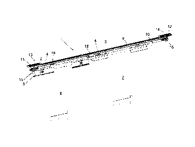
Figure 1 shows a perspective view of the simultaneous displacement device (1)
for
sliding doors of the present invention according to a first preferred
embodiment. As it
can be seen, the sliding door has a first sliding leaf (7) and a second
sliding leaf (8)
CA 02700101 2010-04-14
-8-
hung from an upper guide (5), not shown in this figure. Both sliding leaves
(7) and (8)
have the ability to run in the direction of the upper guide (5), thanks to the
use of
fastening clamps (3) having rolling means (4) which slide on tracks (6)
arranged inside
said upper guide (5). Figure 2 shows a sectional view of the upper guide (5)
where it
can be seen how the different components of the present invention are
integrated.
Again in figure 1, it can be seen that the device (1) of the present invention
comprises a
first cogged belt (9) enabled for the union of the first sliding leaf (7). The
first cogged
belt (9) is established between a first set of cogged pulleys (11) and (12)
which rotate
freely on a first axis (13) and second axis (14) respectively, where said
first (13) and
second axes (14) are integral to the upper guide (5). The device (1) of the
present
invention also comprises a second cogged belt (10) enabled for the union of
the
second sliding leaf (8) and some clutching means (2).
Preferably, the union of the sliding leaves (7, 8) to the cogged belts (9, 10)
is carried
out through the use of connection parts (18), which are fixed at one of their
ends to the
clamps (3) while at the other end they hold the corresponding belt (9, 10).
The second cogged belt (10) is established between a second set of cogged
pulleys
(15, 16) which rotate freely on the first axis (13) and the second axis (14)
respectively.
In turn, the clutching means (2) enable to adopt; a first position where the
first cogged
belt (9) and the second cogged belt (10) move independently, and a second
position
where the first cogged belt (9) and the second cogged belt (10) move
integrally.
Figure 3 shows a perspective view of the first axis (13) according to a first
preferred
embodiment, where it can be seen in greater detail how the different
components of
said axis (13) are arranged. The clutching means (2) are in the second
position, that is,
they are integral to the first cogged belt (9) and the second cogged belt
(10).
Figure 4 shows a perspective view of the second axis (14) according to a first
preferred
embodiment, where it can be seen in greater detail how the different
components are
arranged on said axis (14).
CA 02700101 2010-04-14
-9-
Figure 5 shows a perspective view of the simultaneous displacement device (1)
for
sliding doors of the present invention according to a second preferred
embodiment. As
it can be seen the device (1) comprises a third cogged belt (9') enabled to
join a third
sliding leaf (7'), said third cogged belt (9') being established between a
third set of
cogged pulleys (11') and (12') which rotate freely on a third (13') and fourth
(14') axes,
respectively, where said third (13') and fourth (14') axes are integral to the
upper guide
(5), being the movement of the third cogged pulley (9) synchronized and
opposite to
the movement of the first cogged pulley (9). Through this configuration, it is
possible for
the first and third sliding leaves (7) and (7') to run in a synchronized
manner in opposite
senses and simultaneously together with the second sliding leaf (8).
Figure 6 shows a perspective view of the first axis (13) and the third axis
(13')
according to a second preferred embodiment, in which it can be seen in greater
detail
how the elements of both axes (13, 13') interact.
In order to avoid the derailment of the first and third cogged belt (9) and
(9'), the device
(1) of the present invention comprises a bar (19) integral to the upper guide
(5),
arranged in front of the first and third axes (13) and (13') at the level of
the first cogged
belt (9) and of the third cogged belt (9). Besides, it can be seen a
reinforcement part
(32) joined to the lower end of the first and third axes (13) and (13') to
provide stiffness
to both axes (13, 13') and absorb efforts thereon, ensuring that the gear
mechanism
enabling the synchronism is maintained at all times. The reinforcement part
(32) has a
separating element (33) which avoids the derailment of the second cogged belt
(10).
Figure 7 shows a perspective view of the fourth axis (14') according to a
second
preferred embodiment, where it can be seen in greater detail how the different
components of said axis (14') are arranged.
Figure 8 shows a perspective view of the simultaneous displacement device (1)
for
sliding doors of the present invention according to a third preferred
embodiment. As it
can be seen, the device (1) comprises a fourth cogged belt (10') enabled to
join a
fourth sliding leaf (8') and second clutching means (2').
The fourth cogged belt (10') is established between a fourth set of cogged
pulleys (15')
and (16') which rotate freely on the third axis (13') and the fourth axis
(14') respectively.
CA 02700101 2010-04-14
-10-
In turn, the second clutching means (2') enable to adopt a third position
where the third
cogged belt (9') and the fourth cogged belt (10') move independently, and a
fourth
position where the third cogged belt (9) and the fourth cogged belt (10') move
integrally to allow the simultaneous displacement of the third sliding leaf
(9') and of the
fourth sliding leaf (10'). Through this configuration it is possible for the
first and second
sliding leaves (7) and (8) to run in a sense opposite to the third and fourth
sliding
leaves (7') and (8'), all of them simultaneously.
Figure 9 shows a perspective view of the first axis (13) and of the third axis
(13')
according to a third preferred embodiment, where it can be seen in greater
detail how
the elements of both axes (13, 13') interact.
Figure 10 shows a sectional elevated view of the first axis (13) and of the
third axis
(13') according to a third preferred embodiment.
Figure 11a shows a perspective view of a configuration example of the
clutching
means (2, 2'), where it can be seen that they comprise a wheel (23, 23') and
blocking
means (17, 17'). The blocking means comprise one or more through holes (20)
coinciding with blocking holes (27) drilled on the cogged pulleys (11, 11',
12, 12', 15,
15', 16, 16') between which at least one through element (21) is inserted.
Additionally, the wheel (23, 23') comprises a continuous perimeter groove (28)
which
couples with one or more protruding elements (30) arranged on the pulleys (11,
11', 12,
12', 15, 15', 16, 16'), without said coupling limiting the relative movement
between the
wheel (23, 23') and the corresponding pulley (11, 11', 12, 12', 15, 15', 16,
16'), that is,
the protruding element (30) slides freely inside the continuous perimeter
groove (28).
Likewise, the wheel (23, 23') also comprises one or more discontinuous
perimeter
grooves (29), arranged on the opposite face of the continuous perimeter groove
(28),
which couple with the protruding elements (30) of the pulleys (11, 11', 12,
12', 15, 15',
16, 16') and which block the relative movement between the wheel (23, 23') and
the
corresponding pulley (11, 11', 12, 12', 15, 15', 16, 16').
Figure 11 b shows a perspective view of a second configuration example of the
clutching means (2, 2'), where it can be seen that additionally the wheel also
comprises
flexible protruding pivots (34), the end of which coincides with a plurality
of holes (32)
CA 02700101 2010-04-14
-11-
arranged concentrically in the pulleys (11, 11', 12, 12', 15, 15', 16, 16').
Preferably, the wheel (23, 23') comprises a cogged profile (34) to enable the
synchronism of the third cogged belt (9') and of the first cogged belt (9),
both in the
second and in the third embodiments, as it can be seen in greater detail in
figures 6
and 9.
Figures 12a and 12b show two configuration examples of the pulleys of the
first and
third sets (11, 12) and (11', 12'), where the aforementioned elements can be
seen.
Figures 13a and 13b show two configuration examples of the pulleys of the
second and
fourth sets (15, 16) and (15', 16'), where the aforementioned elements can be
seen.