Note: Descriptions are shown in the official language in which they were submitted.
CA 02700151 2010-04-15
1
Pumpbox
Field of the Invention.
The present invention relates to a pumpbox. In particular, the present
invention
relates to a pumpbox adapted to control the fluid level in a vessel with which
the
pumpbox is associated.
Background Art.
Pumpboxes are widely used in many industrial and metallurgical applications.
Typically, material such as suspensions or slurries enters the pumpbox from
where it
is transferred to another part of a processing plant. Conventional pumpboxes
typically
comprise a vessel in communication with a pump which operates continuously or
semi-continuously to pump material away from the vessel.
In some industrial processes, such as froth flotation plants, pumpboxes are
often
associated with equipment such as flotation cells. In many conventional
flotation
plants, tails streams from one or more cells (or banks of cells) are sent to a
pumpbox
from where the stream is pumped to another part of the plant or to tailings
dams or the
like.
In flotation cells, maintaining a constant fluid level in the cell is crucial
in order to
achieve smooth and consistent operation of the process, and the highest
possible
recovery of valuable mineral. Typically, the control of the fluid level is
achieved
within the flotation cell itself. However, locating level control mechanisms
within a
flotation cell tends to create problems with wear and maintenance.
Thus, there would be an advantage if it were possible to provide a pumpbox
that
provided means for controlling the fluid level in an associated flotation
cell. In
addition, there would be an advantage if the pumpbox also provided means for
classifying the stream exiting the flotation cell and entering the pumpbox.
It will be clearly understood that, if a prior art publication is referred to
herein, this
reference does not constitute an admission that the publication forms part of
the
CA 02700151 2010-04-15
2
common general knowledge in the art in Australia or in any other country.
Throughout this specification, the term "comprising" and its grammatical
equivalents
shall be taken to have an inclusive meaning unless the context of use
indicates
otherwise.
Object of the Invention.
It is an object of the present invention to provide a pumpbox which may
overcome at
least some of the abovementioned disadvantages, or provide a useful or
commercial
choice.
In a first aspect, the invention resides broadly in a pumpbox, the pumpbox
being in
fluid communication with one or more vessels, wherein the pumpbox comprises a
classification portion and level control means adapted to control the level of
fluid
within the one or more vessels.
The pumpbox may be of any suitable form. For instance, in some embodiments of
the
invention the pumpbox may comprise a single chamber. In other embodiments of
the
invention, the pumpbox may comprise a plurality of chambers in fluid
communication
with one another.
In embodiments of the invention in which the pumpbox comprises a plurality of
chambers, the plurality of chambers may be for any suitable purpose. For
instance,
one chamber may house the classification portion of the pumpbox. Further
chambers
may be provided for processing or disposal of the classification products, the
level
control means or the like. In a preferred embodiment of the invention, the
pumpbox
comprises three chambers in fluid communication with one another.
The one or more vessels with which the pumpbox is in fluid communication may
be
of any suitable type. For instance, the one or more vessels may be a mixing
tank,
settling vessel, or any other vessel in which it is necessary or advantageous
to control
the level of fluid. In a preferred embodiment of the invention, the one or
more vessels
may be a flotation cell, or a bank of flotation cells. Any suitable flotation
cell may be
CA 02700151 2010-04-15
3
used in conjunction with the pumpbox of the present invention, such as a
mechanical
flotation cell, pneumatic flotation cell or the like, or a combination of
cells. In a most
preferred embodiment of the invention, the flotation cell may be a Jameson
cell.
Any suitable stream of fluid may be fed from the one or more vessels to the
pumpbox.
For instance, when the one or more vessels comprise flotation cells, it may be
that the
tailings stream from the flotation cell is fed to the pumpbox.
The stream may be fed to the pumpbox using any suitable technique, although in
a
preferred embodiment of the invention, the stream may be fed to the pumpbox
under
gravity.
The pumpbox and the one or more vessels may be formed as a single vessel that
is
divided into the vessel section and the pumpbox section. Alternatively, the
pumpbox
and the one or more vessels may be formed as separate vessels that are in
fluid
communication with one another.
The classification portion of the pumpbox may be of any suitable form and may
classify the stream entering the pumpbox using any suitable technique or any
suitable
property of the stream. For instance, the classification portion may comprise
an
additional piece of equipment (such as a hydrocyclone, magnetic separator or
the like,
or any combination thereof). Alternatively, the classification portion may
classify the
stream on the basis of differences in the properties of the constituent
elements of the
stream, such as density, particle size, buoyancy and so on, or any combination
thereof.
In embodiments of the invention in which the stream entering the pumpbox is a
slurry
(i.e. solid particles carried in a liquid medium), it may be preferred that
the
classification is carried out on the basis of differences in the properties of
the solid
particles. For instance, the particles may be classified on the basis of their
size (such
as by screening the particles) or on the basis of their density. In
embodiments of the
invention in which the particles are classified on the basis of their size
and/or density,
a hydrocyclone (or similar piece of equipment) may be used. Alternatively, the
particles may be classified using gravity. For instance, the particles may be
classified
CA 02700151 2010-04-15
4
on the basis of their settling velocity wherein the larger, denser particles
sink with a
greater velocity than the finer, lighter particles. Alternatively, the fluid
stream may be
subjected to a change of direction upon entering the pumpbox such that finer,
lighter
particles continue to be carried by the fluid stream, while the change in
fluid
momentum caused by the change in direction causes the larger, denser particles
to
drop out of the stream.
In some embodiments of the invention, the stream entering the classification
portion
of the pumpbox may be classified into two or more streams.
The level control means may be of any suitable form provided that the fluid
level in
the one or more vessels may be controlled by actuation of the level control
means. In
a preferred embodiment of the invention, the level control means comprises one
or
more fluid control devices that control the volume of fluid or the flowrate of
fluid that
flows out of the pumpbox. Suitable fluid control devices may include one or
more
valves or any other suitable devices. Any suitable valves may be used as fluid
control
devices, although in some embodiments of the invention, the one or more valves
may
be dart valves. In some embodiments of the invention, the one or more valves
may
simply operate in either a fully open or a fully closed position. However, in
a
preferred embodiment of the invention, the valves may be operable over a wide
range
of positions between the fully open and the fully closed positions.
In some embodiments, the level control means may operate by taking
measurements
(manual, automatic or a combination thereof) of the fluid level within the one
or more
vessels. Depending on the whether the fluid level is above or below a setpoint
value
or, alternatively (or in addition to the fluid level measurement), whether the
fluid level
in the one or more vessels is rising or falling, the level control means may
be actuated
manually, automatically, or by a combination thereof. For instance, if the
fluid level
in the one or more vessels is above a setpoint value, the level control means
may be
actuated to allow fluid to exit the pumpbox or to increase the flowrate of
fluid leaving
the pumpbox, thereby lowering the level in the one or more vessels.
Alternatively, if
the fluid level in the one or more vessels is rapidly decreasing, the level
control means
may be actuated to restrict (or even preclude) the flow of fluid exiting the
pumpbox.
CA 02700151 2010-04-15
Actuation of the level control means may be controlled using any suitable
method.
For instance, actuation of the level control means may involve the manual
actuation of
the fluid control devices. Alternatively, the level control means may be
associated
5 with an actuator which, open receiving a signal (such as from a distributed
control
system (DCS) or similar automated control system), may actuate to cause a
change in
state of the level control means (such as an opening or closing of a valve).
In some
embodiments of the invention, actuation of the level control means may be
controlled
by a combination of manual and automatic operation.
In a preferred embodiment of the invention, the classification of the stream
entering
the pumpbox results in a separation of the stream into two distinct streams: a
classified stream and a rejects stream. In some embodiments of the invention,
the
classification of the stream may also produce a middlings stream.
In preferred embodiments of the invention, at least a portion of the rejects
stream may
report to a separate part of the circuit or plant for further processing.
Alternatively, at
least a portion of the rejects stream may report to the plant tailings stream.
In a most
preferred embodiment, the entire rejects stream leaves the pumpbox for further
processing or for disposal to tailings.
The classified stream may be pumped to another part of the circuit or plant
for further
processing. However, in a preferred embodiment of the invention, at least a
portion of
the classified stream is recycled to the one or more vessels in fluid
communication
with the pumpbox.
While it would be preferred that at least a substantial proportion of the
classified
stream is recycled to the one or more vessels, a skilled addressee will
understand that,
depending on process conditions, this may not always be possible. For
instance, when
the fluid level in the one or more vessels is high or increasing, it may be
preferred that
only a very small portion (or even none) of the classified stream is recycled
to the one
or more vessels in order to avoid overflowing in the one or more vessels.
Thus, in a
preferred embodiment of the invention, the pumpbox may be configured in such a
CA 02700151 2010-04-15
6
manner that at least a portion of the reject stream and at least a portion of
the
classified stream may be combined.
On the other hand, when the fluid level in the one or more vessels is low or
decreasing, it may be possible to recycle the entire classified stream to the
one or more
vessels. In situations in which the fluid level in the one or more vessels is
very low or
decreasing at a high rate, it may be desirable to add further fluid to the
recycled
portion of the classified stream. Similarly, if the portion of the classified
stream being
recycled has a high percentage of solid particles therein, it may be desirable
to dilute
the classified stream prior to recycling to the one or more vessels. Thus, in
some
embodiments of the invention, the pumpbox may be provided with fluid addition
means. Any suitable fluid addition means may be used, such as connecting a
water
line to the pumpbox, either permanently or removably.
Alternatively, it may be desired to provide the pumpbox with means for adding
a
further slurry stream to be combined with the classified stream for recycling
to the one
or more vessels. The further slurry stream may be a stream from a different
part of the
circuit or, in other embodiments of the invention, the further slurry stream
may be a
fresh feed stream.
In another embodiment of the invention, recycling of the at least a portion of
the
classified stream may be isolated such that the entire stream entering the
pumpbox
reports to the rejects stream.
In a further embodiment of the invention, the classification portion of the
pumpbox
may be isolated such that no classification of the stream entering the pumpbox
takes
place. In this embodiment of the invention, the stream entering the pumpbox
may be
entirely recycled to the one or more vessels, may report entirely to the
rejects stream,
or a combination of the two.
The pumpbox of the present invention may be used in any suitable processing
circuit.
For instance, the pumpbox may be used in base metals flotation circuits, other
metalliferous flotation circuits (for instance, platinum group metal flotation
circuits),
CA 02700151 2010-04-15
7
precious metal flotation circuits, coal flotation circuits, industrial mineral
and other
valuable mineral flotation circuits and oil sands flotation circuits.
Brief Description of the Drawings.
An embodiment of the invention will be described with reference to the
following
drawings in which:
Figure 1 illustrates a flowsheet including a pumpbox according to an
embodiment of the present invention; and
Figure 2 illustrates a flowsheet including a pumpbox according to an
alternative
embodiment of the present invention.
Detailed Description of the Drawings.
It will be appreciated that the drawings have been provided for the purposes
of
illustrating preferred embodiments of the present invention and that the
invention
should not be considered to be limited solely to the features as shown in the
drawings.
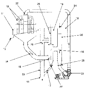
In Figure 1, a flowsheet including a pumpbox 10 according to an embodiment of
the
present invention is illustrated. The pumpbox 10 is in fluid communication
with a
flotation cell 11. Feed material enters the flotation cell 11 through the
downcomers
12 and is separated into a concentrate stream 13 and a tailings stream 14. The
tailings
stream 14 flows under gravity to the pumpbox 10.
The tailings stream 14 enters the pumpbox 10 in a first chamber 19 comprising
the
classification portion 15. In the classification portion 15, the tailings
stream 14 is
forced to change direction, causing the lighter, finer particles to flow
upwards and
form the classified stream 16 which flows into a second chamber 20 of the
pumpbox
10. The coarser, denser particles lose momentum due to the change of direction
of the
tailings stream 14 and report to the rejects stream 17. Further, the upflow
velocity in
classification portion 15 is lower than the settling velocity of the larger or
denser
particles in the tailings stream and hence the larger or denser particles
settle
downwardly through the uplowing fluid in the classification section 15. The
rejects
stream 17 flows into a third chamber 23 of the pumpbox 10, from where it exits
the
pumpbox 10 through an outlet 18. From here, the rejects stream 17 may be
CA 02700151 2010-04-15
8
transferred to another part of the circuit for further processing or may be
discarded, for
instance to a tailings dam.
The classified stream 16 is recycled via pump 21 to the head 22 of the
flotation cell
11. The recycled volume of the classified stream 16 is determined by the head
differential between the fluid level in the flotation cell 11 and the fluid
level in the
second chamber 20. The second chamber 20 of the pumpbox 10 is provided with an
inlet 24 through which water (to dilute the classified stream 16 for
recycling) and/or
slurry, such as a fresh feed slurry, (to combine with the classified stream 16
for
recycling) may be added.
The first chamber 19 further comprises level control means in the form of a
dart valve
25. The dart valve 25 controls the level of fluid in the flotation cell 11,
such that,
when the dart valve 25 is open (as illustrated in Figure 1), a portion of the
classified
stream 16 will flow into the third chamber 23 (shown by arrow 26) and will be
combined with the rejects stream 17. Thus, in situations in which the fluid
level in the
flotation cell 11 is high or rising, the volume of slurry being removed
through the dart
valve 25 will increase in order to avoid overflowing the cell and reducing the
grade of
the concentrate stream 13. Alternatively, when the fluid level in the
flotation cell 11
is low or decreasing, the dart valve 25 may be closed, thereby reducing the
slurry flow
through the dart valve 25 and causing all of the classified stream 16 to be
recycled to
the head 22 of the flotation cell.
The first chamber 19 further comprises a valve 27. It is envisaged that, in
normal
operation, the valve 27 will be maintained in an open position to allow the
flow of the
rejects stream 17 therethrough. However, there may be occasions when it is
desired
that all of the tailings stream 14 entering the pumpbox 10 is recycled to the
head 22 of
the flotation cell 11. Alternatively, the valve 27 may be closed to allow for
maintenance work to be carried out.
Similarly, the second chamber 20 comprises a valve 28 that, under normal
operating
conditions, would be maintained in an open position to allow the classified
stream 16
to be recycled to the head 22 of the flotation cell 11. However, when
recycling is not
CA 02700151 2010-04-15
9
desired, or, for instance, when maintenance of the pump 21 is required, the
valve 28
may be closed.
In Figure 2 there is illustrated a flowsheet showing a pumpbox 10 according to
an
alternative embodiment of the present invention. In this embodiment, the pipe
30
carrying the tailings stream 14 from the flotation cell 11 changes direction
as it enters
the classification portion 15 in a first chamber 19 of the pumpbox 10. This
change of
direction causes the coarser, denser particles to drop out of the slurry
stream and form
the rejects stream 17 which exits the pumpbox 10 through an outlet 18 in the
third
chamber 23. Further, the upflow velocity in classification portion 15 is lower
than the
settling velocity of the larger or denser particles in the tailings stream and
hence the
larger or denser particles settle downwardly through the uplowing fluid in the
classification section 15. The classified stream 16 (comprising the finer,
lighter
particles) flows into the second chamber 20 from where it is recycled via a
pump 21 to
the head 22 of the flotation cell 11.
The first chamber 19 comprises level control means in the form of a dart valve
25. As
with the embodiment illustrated in Figure 1, closing the dart valve 25 causes
the entire
classified stream 16 to be recycled to the head 22 of the flotation cell 11,
whereas
opening the dart valve 25 causes at least some of the classified stream 16 to
flow
through the dart valve seat 31 and combine with the rejects stream 17 as
indicated by
arrow 32.
The pumpbox is provided with a valve 27 that, when closed, ensures that none
of the
tailings stream 14 entering the pumpbox 10 reports to the reject stream 17.
Similarly,
a second valve 28 is provided so that the pump 21 may be isolated when
maintenance
is required, or when no recycling of the classified stream 16 is desired.
A skilled addressee will understand that the pumpbox of the present invention
provides numerous advantages over the prior art. Firstly, by providing the
pumpbox
(rather than the flotation cell) with the level control means, the service
life of the level
control means may be significantly improved.
CA 02700151 2010-04-15
In addition, the pumpbox of the present invention allows for the preferential
removal
of coarse particles from the stream entering the pumpbox and the recycling of
fine
material to the cell. A skilled addressee will understand that recycling of
fine material
may ultimately result in an increase in recovery of valuable mineral within
the
5 flotation cell.
Those skilled in the art will appreciate that the present invention may be
susceptible to
variations and modifications other than those specifically described. It will
be
understood that the present invention encompasses all such variations and
10 modifications that fall within its spirit and scope.