Note: Descriptions are shown in the official language in which they were submitted.
CA 02700230 2010-03-19
WO 2009/085064
PCT/US2008/010913
1
METHOD AND APPARATUS FOR OPTICALLY PROGRAMMING A PROJECTILE
FIELD OF INVENTION
The invention in general relates to programming of an
in-flight projectile fired from a fire control device and,
more specifically, to the use of optically modulated signals
for programming of the projectile.
BACKGROUND OF INVENTION
Existing methods for programming in-flight projectiles
have distinct drawbacks. The disadvantage of using the
10erlikon AHEAD' technique is that it consumes a great deal
of power. The programming coils used in this system are
bulky and heavy. The use of radio frequency (RF) to
transmit the programming signals ('NAMMO' radio frequency)
is subject to interference from IED suppression technology.
BOFORS Larson Patents limited use of this technology to
closed bolt designs.
U.S. Patent Pub. No. 2005/0126379 discloses RF data
communication link for setting electronic fuzes. Whereas
the programming of the projectile is only limited to pre-
launch programming. It does not provide any method to
program an in-flight projectile.
U.S. Patent No. 5,102,065 discloses a system to correct
the trajectory of a projectile. It transmits corrections
signal via a laser beam. The corrections are transmitted to
the shell and the shell receives the information and applies
it in order to deflect its trajectory. However, the use of
self guided shells is very expensive and can only be used
CA 02700230 2010-03-19
WO 2009/085064
PCT/US2008/010913
2
for the destruction of even costlier targets. Also U.S.
Patent No. 4406430 discloses an optical remote control
arrangement for a self guided projectile. The remote
control disclosed helps the projectile in hitting its
desired target by modifying the trajectory of the
projectile. Programming of the projectiles which are not
self guided is not discussed in both of the patents.
U.S. Patent No. 6,216,595 discloses a process for the
in-flight programming of the trigger time for a projectile
element. The trigger time is transmitted via radio
frequency signals. The use of radio frequency adds several
disadvantages to effective transmission such as interference
from IED suppression technology.
U.S. Patent No. 6,170,377 discloses a method and
apparatus for transmission of programming data to a time
fuze of a projectile via an inductive transmission coil. The
inductive coils are very bulky and heavy.
U.S. Patent No. 6,138,547 discloses a method and system
for programming fuzes by using electric programming pulses
to transmit data between a programmable fuze and a
programming device.
In the systems disclosed in the above prior art, due to
oscillation of the projectile, it is difficult to maintain
consistent contact or proximity between the external source
of the programmed pulses and the conductor located on the
projectile. Also, both these methods require extensive
modification of the weapon design which limits their use.
CA 02700230 2010-03-19
WO 2009/085064
PCT/US2008/010913
3
SUMMARY OF THE INVENTION
It is an object of the present invention to modulate
the signal of a projectile with a set of instructions.
It is another object of the invention to allow for
transmission of modulated optical signals to projectiles
from a transmitter associated with a weapon.
It is still another object of the invention to program
a fuze circuit by using the modulated optical signal.
The invention comprises a fire control device fitted
with an optical transmitter to transmit a modulated optical
signal, and a projectile fitted with a translucent housing
(collector) for collecting the modulated optical signals, a
fuze and an optical sensor.
The optical transmitter emits programming signals in
the direction of the projectile (in-flight) with an adequate
beam width and strength.
The optical light is modulated in amplitude to create
an optical signal. Normally, the programming signal would
include identification of a function mode and, as
appropriate, an optimum function time. A logarithmic input
allows the fuze electronics to distinguish the modulated
signal input from other optical rays.
After transmission, the optical beam is collected by a
translucent collector, mounted on the projectile. The
CA 02700230 2014-12-09
31512-6
4
collector refracts, and/or reflects and focuses the collected
modulated optical signal to the optical sensor. The sensor
becomes energized upon receiving the modulated optical signals.
The energized sensor modulates the fuze circuit.
In some embodiments, there is provided a method for
optically programming an in-flight projectile fired from a fire
control device comprising the steps of: a) transmitting
modulated optical signals to said projectile from a transmitter
attached to said fire control device; b) collecting said
modulated optical signals by a collector mounted on a nose of
said projectile; c) receiving said modulated optical signals
from said collector by a sensor disposed within said
projectile, wherein said modulated optical signals activate
said sensor; and d) modulating a fuze circuit by said activated
sensor, wherein transmitting modulated optical signals to said
projectile comprises transmitting modulated optical signals
directly to said projectile.
In some embodiments, there is provided a method for
optically programming an in-flight projectile fired from a fire
control device comprising the steps of: a) transmitting
modulated optical signals to said projectile from a transmitter
attached to said fire control device; b) collecting said
modulated optical signals by a collector disposed in a nose of
said projectile, wherein said collector is made of translucent
material; c) receiving said modulated optical signals from said
collector by a sensor disposed within said projectile, wherein
said modulated optical signals activate said sensor; and d)
modulating a fuze circuit by said activated sensor, wherein
transmitting modulated optical signals to said projectile
CA 02700230 2014-12-09
31512-6
4a
comprises transmitting modulated optical signals directly to
said projectile.
In some embodiments, there is provided a system for
optically programming an in-flight projectile fired from a fire
control device, said system comprising: a) a transmitter
attached to said fire control device for transmitting modulated
optical signals directly to said projectile; b) a collector
mounted on a nose of said projectile for collecting said
modulated optical signals, wherein said collector is made of
translucent material; c) a sensor, disposed within said
projectile for receiving said modulated optical signals from
said collector, wherein said modulated optical signals activate
said sensor; and d) a fuze circuit, wherein said fuze circuit
is modulated by said activated sensor.
In some embodiments, there is provided a system for
optically programming an in-flight projectile fired from a fire
control device, said system comprising: a) means for
transmitting modulated optical signals to said projectile from
a transmitter attached to said fire control device; b) means
for collecting said modulated optical signals by a collector
mounted on a nose of said projectile; c) means for receiving
said modulated optical signals from said collector by a sensor
disposed within said projectile, wherein said modulated optical
signals activate said sensor; and d) means for modulating a
fuze circuit by said activated sensor, wherein said means for
transmitting modulated optical signals to said projectile
comprises means for transmitting modulated optical signals
directly to said projectile.
CA 02700230 2014-12-09
31512-6
4b
The foregoing and other objects, features and
advantages of the invention will be apparent from the following
more particular description of the invention, as illustrated in
the accompanying drawings.
BRIEF DESCRIPTION OF DRAWINGS
Embodiments of the present invention, hereafter
described in conjunction with the appended drawings, are
provided to illustrate and not to limit the present invention,
wherein like designations denote like elements, and in which:
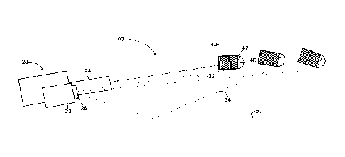
FIG. 1 depicts a weapon for firing a projectile and a fire
control device 22 for transmission of optical signals to the
in-flight projectile 40.
FIG. 2, comprising Figs. 2a-2d, depicts reception of the
optical signals (32, 34) by the in-flight projectile 40.
FIG. 3, comprising Figs. 3a and 3b, depicts use of rotation to
allow for efficient optical signal reception.
FIG. 4, comprising Figs. 4a and 4b, depicts yaw cycle of an in-
flight projectile 40.
CA 02700230 2010-03-19
WO 2009/085064
PCT/US2008/010913
FIG. 5 depicts an alternate embodiment with a translucent
lens 70 on the collector 44.
FIG. 6 depicts the convergence of modulated optical signals
(32, 34) with the in-flight projectile 40.
DETAILED DESCRIPTION OF THE PREFERRED EMBODIMENTS
Embodiments of the present invention provide method and
system for optically programming an in-flight projectile 40.
In the description of the present invention, numerous
specific details are provided, such as examples of
components and/or mechanisms, to provide a thorough
understanding of the various embodiments of the present
invention. One skilled in the relevant art will recognize,
however, that an embodiment of the present invention can be
+practiced without one or more of the specific details, or
with other apparatus, systems, assemblies, methods,
components, materials, parts, and/or the like. In other
instances, well-known structures, materials, or operations
are not specifically shown or described in detail to avoid
obscuring aspects of embodiments of the present invention.
FIG. 1 illustrates a weaponry system 100 comprising a
weapon (firing mechanism) 20, fire control device 22 for
firing a projectile 40. The fire control device 22 includes
an optical transmitter 26. The weapon 20 fires the
projectile 40 while the transmitter 26 transmits optical
signals (32, 34) to the in-flight projectile 40.
CA 02700230 2010-03-19
WO 2009/085064
PCT/US2008/010913
6
The weapon 20 can be a firearm, cannon, launcher,
rocket pod or aircraft or the like. Many weapons include
barrels 24.
Optical transmitter 26 is a light generating source
comprising, for example, one or more light emitting diodes,
laser beam sources and the like. The transmitter 26 can
transmit optical signals (32, 34) of discrete frequencies in
the UV, visual or IR spectrums.
In one embodiment of the invention the optical signals
(32, 34) transmitted by the transmitter 26 to the projectile
40 are digital programming signals, which are modulated by
the fire control device 20 to carry a set of instructions.
The set of instructions are programming protocols.
Normally, the programming signal would include a function
mode and, as appropriate, an optimum function time.
The transmitter 26 can also send synchronizing signals
along with the programming signals. The synchronizing
signals carry information such as pre-determined time slot
for which a fuze 48 (disposed in the projectile) should
accept the input from the signals. After the time window is
reached, the fuze 48 will no longer accept any signal. This
helps in preventing the fuze 48 from interruption by any
foreign signals (i.e. signals which are not sent by the
transmitter 22 of the fire control device). This may also
help in reducing the power consumption by the fuze 48.
FIG. 2 illustrates various components of the projectile
40 and their functionalities. The projectile 40 comprises a
nose 42, a collector 44, one or more sensors 46 and an
CA 02700230 2010-03-19
WO 2009/085064
PCT/US2008/010913
7
electronic fuze 48. The nose 42 is ogive shaped and
incorporates the collector 44. The collector 44 has a
translucent housing which protects the underlying sensor 46.
Further, the sensor 46 is attached to the electronic fuze
48.
The modulated optical signals 30 are transmitted in the
direction of the projectile 40 with an adequate beam width
and strength so as to optimize the transmission. These
transmitted modulated optical signals (32, 34) intersect the
projectile 40 flight path allowing the signals to be
collected by the collector 44 as illustrated in FIG. 2(b)
and 2(c). The collector 44 refracts, reflects and focuses
the modulated optical signals (32, 34) to the sensor 46.
The sensor 46 distinguishes the modulated optical signals
(32, 34) from other signals to energize circuitry. The
energized circuitry 46 uses logarithmic input response to
modulate the electronic circuit of the fuze 48 which is
illustrated in FIG. 2(d).
FIG. 3 illustrates varying degrees of rotation of the
in-flight projectile 40 to position the projectile 40 to
receive optical signals (32, 34) optimally. The rotation is
induced by barrel lands and grooves acting on a driving
band. FIG. 3 (a) shows an exploded view of the collector 44
position disposed in the nose 42 of the projectile 40
thereby enabling the collector 44 to receive direct optical
signals 32 as well as reflected optical signals 34,
reflected from intermediate surfaces 50. FIG. 3 (b) shows
an exploded view of the position of the collector 44
receiving only reflected optical signals 34. In this
CA 02700230 2010-03-19
WO 2009/085064
PCT/US2008/010913
8
position the angle of inclination of the axis of rotation 60
of the projectile 40 with respect to vertical plane is such
that it does not allow the collector 44 to receive direct
optical signals 32.
FIG. 4 illustrates a varying yaw cycle of the in-flight
projectiles 40. FIG. 4(a) illustrates how yaw enables the
projectile 40 to rotate about its vertical axis. Yaw can be
induced on projectiles 40 through a number of well known
mechanical factors. Yaw can position the projectile 40 to
receive optical signals (32, 34) more effectively. FIG.
4(b) illustrates how the transmission of optical signals 30
is optimized with redundant signals. The transmitter 26
emits excessive optical signals to optimize reception. The
induced rotation also provides for natural screening of
sun's rays that can interfere with optical signal
transmission. By incorporating redundant signals that are
repeated at a rate that coincides with the rotation of the
projectile, direct sun ray's can be screened allowing for
improved signal processing.
In an alternate embodiment of the invention as shown in
FIG. 5, the collector 44 can be mounted at any position on
the nose 42 of the projectile 40. The collector 44 can also
incorporate translucent lens 70 to optimize collection of
transmitted direct signal 32 and/or reflected signal 34.
As illustrated in FIG. 6, the transmitter 26 is focused
and positioned to use geometric location position and beam
divergence 110 to transmit light directly into the
CA 02700230 2010-03-19
WO 2009/085064
PCT/US2008/010913
9
projectile path. FIG. 6 further illustrates the signal
strength distance 90. Beyond this distance the intensity of
the transmitter 26 diminishes and the intersection of the
modulated optical signal and the in-flight projectile does
not occur. The modulated optical signals intersect the
projectile flight path for effective reception of the signal
in the effective signal reception zone 80. This effective
signal reception zone 80 can be varied by changing
parameters such as signal strength and width. The
transmission of the modulated optical signals depends on
multiple factors such as post firing IR transmission
resonance 82, gun jump and shock wave effect 83, muzzle
flash and burnt powder residue zone 84, battery rise time 86
and projectile yaw frequency.
While embodiments of the present invention have been
illustrated and described, it will be clear that the present
invention is not limited to these embodiments only.
Numerous modifications, changes, variations, substitutions
and equivalents will be apparent to those skilled in the
art, without departing from the spirit and scope of the
present invention, as described in the claims.