Note: Descriptions are shown in the official language in which they were submitted.
CA 02700323 2011-02-14
25448-830
Spraying Device and Method of Using Same
Field of the Invention
The present invention relates to a device for spraying a fluid and
particularly, but not exclusively
to a device for spraying fluids such as fragrances, deodorizing fluids and/or
a pest control
materials or the like. The present invention also relates to a method of using
such a device.
Background
Prior art devices for spraying fragrances, deodorising agents and sanitising
fluids into a room
generally consist of a device containing a removable source of fluid. With
such an arrangement
once the source of fluid has been completely exhausted, the source can be
replaced rather than
replacing the entire device. Typically such sources come in many forms,
including containers,
bottles, cans and cartridges (generically, all such containers, bottles, cans
and cartridges
hereinafter will be referred to as "refills"). Such refills can be pump sprays
or aerosols, including
metered and non-metered versions thereof.
Known prior art devices typically comprise a housing having an opening through
which the fluid is
sprayed. A part of the housing is movable/removable to permit a refill to be
introduced and
subsequently removed from the interior of the device. The device further
comprises a
mechanically actuated arm or the like therein which is adapted to periodically
activate in order to
press down on a spray head connected to the refill, resulting in fluid passing
from the body of the
refill, through the spray head and out of the opening in the housing into the
surrounding
environment.
The shape of a refill is typically standardised to a certain degree, as such,
spraying devices may
unwittingly provide an opportunity to facilitate vandalism or dangerous
behaviour. Specifically,
vandals or the like may seek to intentionally insert a dangerous source of
sprayable fluid into a
spraying device. For instance, where the device is for spraying a fragrance
and the refill is an
aerosol of a standard size, one form of vandalism and/or intentional abuse
could be the insertion
of a paint aerosol into the device. The resulting damage from such abuse could
be substantial.
Such abuse would likely be associated with a significant health and safety
risk. Clearly it would
be desirable from a user's perspective to be protected from such dangerous
behaviour and/or
acts of vandalism.
1
CA 02700323 2010-03-19
WO 2009/037491 PCT/GB2008/003212
Summary of Invention
According to a first aspect of the present invention there is provided
therefore a spraying device
with a refill of fluid therein, wherein the refill comprises a body forming a
reservoir for the fluid and
a spray head located at the uppermost part of the refill in fluid
communication with the reservoir,
and wherein the device comprises a housing adapted to receive the refill
therein and having an
aperture suitable for permitting, in use, the spraying of the fluid from an
exit orifice of the spray
head therethrough, the device further comprising actuation means configured
for periodic
actuation of the refill, wherein the device is provided with detection means
configured to
distinguish between at least one area of lower reflectance and at least one
area of relatively
higher reflectance on the spray head of said refill.
Reflectance relates to radiation striking a surface, some of it is absorbed
and some is reflected.
Reflectance is expressed as a unitless proportion. For the avoidance of doubt,
the term "lower
reflectance" is used herein as a relative term with reference to the term
"higher reflectance";
"lower" may include areas of zero or near zero reflectance.
The body of the refill may be elongate, and the body may be provided with a
valve stem at an
upper portion of the body remote from the base of the body. At least a portion
of the valve stem
may be connected to the spray head to permit, in use, fluid to pass from the
body of the refill,
through the valve stem and through the spray head to the exit orifice where
the fluid is sprayed
into the surrounding environment.
Preferably the spray head is provided with one area of lower reflectance and
one area of
relatively higher reflectance.
Preferably the detection means are configured to operate to distinguish
between areas of differing
reflectance during movement of the spray head.
Advantageously the device according to the present invention may be able to
detect when a user
attempts to use the device with a potentially dangerous refill and, further,
the device is preferably
configured to deny the actuation means from activating and/or deny subsequent
activation whilst
such a refill is loaded in the device to prevent and/or limit any damage that
could result from
actuating the refill.
A further advantage of the devices of the present invention is that they may
be able to provide an
improved end of life indication. In use, when a device according to the
present invention detects
2
CA 02700323 2010-03-19
WO 2009/037491 PCT/GB2008/003212
the at least one area of lower reflectance and at least one area of relatively
higher reflectance on
the spray head of the refill loaded therein, a counting mechanism may be
triggered. The counting
mechanism may be calibrated to allow a pre-determined number of actuations of
the refill which
corresponds to the quantity of fluid stored in a refill. The counting
mechanism may be operable in
use, and after the pre-determined number of actuations has been reached, to
prevent the device
from causing further actuations of that refill until a user replaces the
refill and/or resets the device.
The device may automatically reset every time a refill is loaded into the
device. This end of life
indication may be advantageous as the power consumption of the device will be
minimised, this
would be particularly advantageous where the device is battery powered or the
like.
The counting mechanism may be linked to an indicator that is adapted to
communicate to the
user of the device that a used or spent refill needs to be replaced.
Preferably the pre-defined number of actuations is calculated to correspond to
the quantity of fluid
in the refill.
Preferably the detection means are in direct communication with the actuation
means such that,
in use, the detection means may instruct the actuation means not to activate.
Alternatively a control means may be provided that is in direct communication
with both the
detection means and the actuation means, said control means being operative to
receive an input
from the detection means and being operative to instruct the actuation means
to activate or not
depending on the received input.
The control means may be provided in the form of a micro processor, a circuit
provided on a PCB
or in the form of another convenient component(s).
Preferably the actuation means are operable to cause actuation of the refill
spray head by
imparting a substantially downward force on the spray head. Said substantially
downward force
is preferably sufficient to cause the spray head to move in a substantially
downward direction to
open the fluid pathway between the body of the refill and the exit orifice of
the spray head to
spray a quantity of fluid out of the opening in the housing into the
surrounding environment. Once
a quantity of fluid has been sprayed, the device may be configured such that
the refill's inherent
resilience and/or internal pressure is capable of applying a substantially
upward force on the
spray head sufficient to return the actuation means to its starting position
without the need for
power to be applied to said means.
3
CA 02700323 2010-03-19
WO 2009/037491 PCT/GB2008/003212
The detection means of the present invention is adapted, in use, to
distinguish between areas of
differing reflectance on a spray head of a refill. Preferably the detection
means is capable of
distinguishing as mentioned by interrogating the refill. The refill spray head
may be interrogated
by the detection means emitting radiation toward the spray head and collecting
reflected radiation
such that the amount of reflectance can be attributed specifically or
approximately or generally to
one or more portions of the spray head. Such attribution may permit the
detection means to
directly, or in combination with a control unit, to determine whether any
areas of differing
reflectance are present on the spray head. If there are no areas of differing
reflectance on the
spray head of the refill there should be a substantially constant level of
reflected radiation.
Therefore in an alternative arrangement, the interrogation of the refill by
the detection means may
permit the detection means to detect whether at least one differing level of
reflected radiation is
detected without attributing the detected level of reflectance to a specific
portion of the spray
head. Such detection may permit the detection means to directly, or in
combination with a control
unit, determine whether any areas of differing reflectance are present on the
spray head.
The detection means may be configured to make a determination that there are
differing levels of
reflectance between at least two separate portions of the spray head when the
reflectance from
one portion is at least 0.5 times greater than from the a separate portion of
the spray head, and
preferably at least 2 times greater, and more preferably at least 5 times
greater, and even more
preferably at least 10 times greater, and even more preferably still at least
50 times greater, and
most preferably at least 100 times greater.
As mentioned, it is preferable for the detection means to be configured to be
operable to
distinguish between areas of differing reflectance during the movement of the
spray head. Even
more preferably the detection means is configured to only be so operable
during the movement of
the spray head. This may be advantageous since this would permit the detection
means to have
a fixed location within the device and have no moving parts, thus reducing the
cost of the
detection means and rendering them less likely to fail during the life of the
device. Additionally,
with such an arrangement the detection means may have a predefined field of
view allowing a
refill manufacturer more defined parameters for ensuring the spray head is
suitably detectable by
the detection means. A further advantage exists where the device is to be
battery powered as
the detection means will only draw power during the actuation of the refill.
Preferably the detection means may be confined to only be operable to
distinguish between areas
of differing reflectance during the substantially upward movement of the spray
head, i.e. the
upward movement of the spray head after the downward movement caused by the
actuation
means. In this arrangement the inherent resilience and/or internal pressure of
the refill may be
4
CA 02700323 2010-03-19
WO 2009/037491 PCT/GB2008/003212
sufficient to return the actuation means to its starting position without
power being applied to said
means. Such an arrangement may be particularly advantageous since the
substantially upward
movement of the spray head may be achieved without power being applied to the
activation
means, thus reducing or eliminating electrical noise/interference produced by
the device. The
reduction in electrical noise/interference may improve the ability of the
detection means to
distinguish areas of differing reflectance on the spray head, thus improving
the reliability of the
detection means whilst allowing a relatively inexpensive detection means to be
used.
The detection means may be operable to determine whether a refill is loaded
into the device
before being operable to distinguish between areas of differing reflectance.
In this arrangement
the detection means may be operable to interrogate the location within the
device normally
occupied by a spray head of a refill when loaded into the device, if the
detection means does not
detect any reflectance, or a predetermined level of reflectance, this
situation may be indicative of
the absence of a refill in the device and the detection means will prevent the
actuation means
from activating. This arrangement may also be advantageous as it will prevent
the actuation
means from periodically activating after a user has removed a spent refill and
before a new refill
is loaded into the device.
Preferably the detection means are provided with a fixed location within the
device and,
preferably, have a fixed field of view with respect to the spray head of a
refill or the area normally
occupied by the spray head when a refill is loaded in the device.
Alternatively or additionally the detection means may be configured to move in
order to
interrogate the spray head or the area normally occupied by the spray head.
The detection may
be movable in a substantially horizontal direction and/or a substantially
vertical direction and/or in
at least two directions. The detection means may be able to pivot about a
single position to
perform the scan. The detection means may be provided with a wide-angle lens,
such as a fish
eye lens, to provide a wide field of view when performing the interrogation of
the refill.
The detection means may be provided in the form of one or more sensors. The
sensor(s) is
preferably provided with an integrated radiation emitter that is adapted to
emit radiation and
further provided with a collecting portion that is adapted to collect any
reflected radiation.
Alternatively, the sensor may only comprise the collecting portion, the
radiation emitter being a
separate component that is positioned so that it is capable of emitting
radiation toward the spray
head such that at least some of the reflected radiation may be collected by
the collecting portion.
CA 02700323 2010-03-19
WO 2009/037491 PCT/GB2008/003212
Preferably the sensor(s) is an optical sensor in the form of an Infra-Red
sensor, more preferably a
passive Infra-Red sensor. Alternatively or additionally, the optical sensor(s)
may be provided in
the form of a light sensor or laser sensor.
The detection means may be configured to interrogate with an effective range
of up to 100mm,
the effective range being the distance any interrogation must travel once
reflected by the spray
head in order to be detected by the detection means, ie, the distance between
the detection
means or source of the interrogation to the spray head in addition to the
distance the reflected
interrogation must travel to the detection means to be collected and detected.
Preferably the
detection means with an effective range of up to 50mm, and more preferably up
to 20mm, and
even more preferably up to 10mm, and most preferably up to 5mm.
According to an alternative aspect of the present invention there is provided
therefore a spraying
device with a refill of fluid therein, wherein the refill comprises a body
forming a reservoir for the
fluid and a spray head located at the uppermost part of the refill in fluid
communication with the
reservoir, and wherein the device comprises a housing adapted to receive the
refill therein and
having an aperture suitable for permitting, in use, the spraying of the fluid
from an exit orifice of
the spray head therethrough, the device further comprising actuation means
configured for
periodic actuation of the refill, wherein the device is provided with
detection means configured, in
use, to interrogate the spray head to distinguish between at least one area of
lower reflectance
and at least one area of relatively higher reflectance on the spray head of
said refill, characterised
in that the spray head is provided with at least one portion shaped to
substantially reflect the
detection means interrogation back toward said means and is provided with at
least one portion
shaped to substantially deflect the detector means interrogation away from
said means.
In the alternative aspect of the present invention the at least one area of
lower reflectance is
provided by the at least one portion of the spray head that is shaped to
deflect the interrogation
from the detection means away from the detection means such that a lower
amount of the
interrogation (be it radiation for example) is detected by said means in
comparison to the amount
of interrogation detected by the detection means when the interrogation of the
at least one portion
shaped to reflect said interrogation toward said means, the area of higher
reflectance.
According to a further alternative aspect of the present invention there is
provided therefore a
spraying device with a refill of fluid therein, wherein the refill comprises a
body forming a reservoir
for the fluid and a spray head located at the uppermost part of the refill in
fluid communication
with the reservoir, and wherein the device comprises a housing adapted to
receive the refill
therein and having an aperture suitable for permitting, in use, the spraying
of the fluid from an exit
6
__ ._ .. . ...--T
CA 02700323 2010-03-19
WO 2009/037491 PCT/GB2008/003212
orifice of the spray head therethrough, the device further comprising
actuation means configured
for periodic actuation of the refill, wherein the device is provided with
detection means configured,
in use, to interrogate the spray head to distinguish between at least one area
of lower reflectance
and at least one area of relatively higher reflectance on the spray head of
said refill, characterised
in that the spray head is provided with at least one portion shaped to
substantially reflect the
detection means interrogation back toward said means and is provided with at
least one portion
shaped or cutaway to avoid the interrogation of the detector means.
In the further alternative aspect of the present invention the at least one
area of lower reflectance
is provided by the at least one portion of the spray head that is shaped or
cutaway to avoid the
interrogation from the detection means such that a lower or zero amount of the
interrogation (be it
radiation for example) is detected by said means in comparison to the amount
of interrogation
detected by the detection means when the interrogation of the at least one
portion shaped to
reflect said interrogation toward said means, the area of higher reflectance.
According to a yet further alternative aspect of the present invention there
is provided therefore a
spraying device with a refill of fluid therein, wherein the refill comprises a
body forming a reservoir
for the fluid and a spray head located at the uppermost part of the refill in
fluid communication
with the reservoir, and wherein the device comprises a housing adapted to
receive the refill
therein and having an aperture suitable for permitting, in use, the spraying
of the fluid from an exit
orifice of the spray head therethrough, the device further comprising
actuation means configured
for periodic actuation of the refill, wherein the device is provided with
detection means configured,
in use, to interrogate the spray head to distinguish between at least one area
of lower reflectance
and at least one area of relatively higher reflectance on the spray head of
said refill, characterised
in that the interrogation emitted from detection means is configured to be
detectable over a
predefined distance that is substantially equal to the effective range, and
wherein the spray head
is provided with at least one portion shaped to substantially reflect the
detection means
interrogation back toward said means and is provided with at least one portion
shaped or cutaway
relative to the location of the detection means.
As discussed above, the effective range is used herein to relate to the
distance any interrogation
must travel in order to be detected by the detection means, ie, the distance
between the detection
means or source of the interrogation to the spray head in addition to the
distance the reflected
interrogation must travel once reflected by the spray head to the detection
means to be collected
and detected.
7
CA 02700323 2010-03-19
WO 2009/037491 PCT/GB2008/003212
In this further alternative arrangement, by tuning the distance the
interrogation is able to travel
such that it is capable of travelling the distance between the non-cutaway
portion of the spray
head and back again after reflection, it is possible to distinguish between
one area of lower
reflection and one area of higher reflection. Due to the tuning of the
interrogation, the amount of
interrogation collected by the detection means would be less for the
interrogation reflected from
the cutaway portion than from the non-cutaway portion of the spray head, this
difference in
reflectance being detectable by the detection means, thus indicating two areas
of differing
reflectance. The tuning of the distance or the intensity of the interrogation
is capable of travelling
could be made greater or smaller than the abovementioned distance, what is
important is that the
interrogation is tuned such that the cutaway portion of the spray head
produces a lesser amount
of reflected interrogation compared with the non-cutaway portion which is
collectable and
detectable by the detection means.
According to a second aspect of the present invention there is provided
therefore a spraying
device comprising a housing adapted to receive a refill of fluid therein and
having an aperture
suitable for permitting, in use, the spraying of the fluid from the refill
therethrough, the device
further comprising actuation means configured for periodic actuation of the
refill, wherein the
device is provided with detection means configured to distinguish, in use,
between at least one
area of lower reflectance and at least one area of relatively higher
reflectance on a spray head of
said refill.
According to an alternative aspect of the present invention there is provided
therefore a spraying
device adapted to receive a refill of fluid therein and having an aperture
suitable for permitting, in
use, the spraying of the fluid from the refill therethrough, the device
further comprising actuation
means configured for periodic actuation of the refill, wherein the device is
provided with detection
means configured, in use, to interrogate a spray head of the refill,
characterised in that the device
is configured to interrogate a refill having a spray head wherein at least one
portion of the spray
head is shaped to substantially reflect the detection means interrogation back
toward said means
and at least one portion of the spray head is shaped to substantially deflect
the detector means
interrogation away from said means such that, in use, the device can
distinguish between at least
one area of lower reflectance and at least one area of relatively higher
reflectance on the spray
head of said refill.
According to a further alternative aspect of the present invention there is
provided therefore a
spraying device adapted to receive a refill of fluid therein and having an
aperture suitable for
permitting, in use, the spraying of the fluid from the refill therethrough,
the device further
comprising actuation means configured for periodic actuation of the refill,
wherein the device is
8
CA 02700323 2010-03-19
WO 2009/037491 PCT/GB2008/003212
provided with detection means configured, in use, to interrogate a spray head
of the refill,
characterised in that the device is configured to interrogate a refill having
a spray head wherein at
least one portion of the spray head is shaped to substantially reflect the
detection means
interrogation back toward said means and at least one portion of the spray
head is shaped or
cutaway to avoid interrogation by the detector means such that, in use, the
device can distinguish
between at least one area of lower reflectance and at least one area of
relatively higher
reflectance on the spray head of said refill.
According to a yet further alternative aspect of the present invention there
is provided therefore a
spraying device adapted to receive a refill of fluid therein and having an
aperture suitable for
permitting, in use, the spraying of the fluid from an exit orifice of the
spray head therethrough, the
device further comprising actuation means configured for periodic actuation of
the refill, wherein
the device is provided with detection means configured, in use, to interrogate
a spray head on the
refill to distinguish between at least one area of lower reflectance and at
least one area of
relatively higher reflectance on the spray head of said refill, characterised
in that the interrogation
emitted from detection means is configured to be detectable over a predefined
distance that is
substantially equal to the effective range, and wherein the spray head for use
with the device is
provided with at least one portion shaped to substantially reflect the
detection means
interrogation back toward said means and is provided with at least one portion
shaped or cutaway
relative to the location of the detection means.
According to a third aspect of the present invention there is provided
therefore a method of
spraying a fluid from a device, the method comprising the steps of loading a
refill of fluid in a
spray device according to any of the first or second aspects of the present
invention, placing the
device in an operation mode, said mode being configured to cause activation of
the actuation
means, said actuation means periodically operating to bear against a spray
head of the refill and
causing the movement thereof to release a quantity of fluid from the refill,
said released fluid
being sprayed from the device through an aperture in the housing into the
surrounding
environment, characterised in that detection means provided in the device are
operable in the
operation mode to detect and distinguish between at least one area of lower
reflectance and at
least one area of relatively higher reflectance on a spray head of said refill
or within the area
normally occupied by said spray head.
Preferably the detection means are operable during the activation of the
actuation means and the
movement of the refill spray head. Even more preferably the detection means
are only operable
during the activation of the actuation means. Most preferably the detection
means are configured
to only be operable during the substantially upward movement of the refill
spray head, i.e. the
9
CA 02700323 2010-03-19
WO 2009/037491 PCT/GB2008/003212
upward movement of the spray head after the downward movement caused by the
actuation
means.
The method may comprise a preceding step before activation of the actuation
means wherein the
detection means performs an initial interrogation of the area within the
housing normally occupied
by the spray head of a refill when a refill is loaded in the device. In this
preceding step if the
detection means does not detect any reflectance, or a predetermined level of
reflectance, this
may be indicative of the absence of a refill in the device and the detection
means will prevent the
actuation means from activating.
The method of the third aspect of the present invention is preferably operable
to prevent the
activation of the actuation means if the detection means is unable to detect
and distinguish
between said at least two areas of differing reflectance. Alternatively the
method of the third
aspect of the present invention is preferably operable to prevent the further
activation of the
actuation means if the detection means is unable to detect and distinguish
between said at least
two areas of differing reflectance. The prevention of activation or further
activation may be
maintained until a user resets the device and/or initiates a manual override
of the ongoing
prevention.
Turning to the refill to be used in the aforementioned devices or methods, the
areas of differing
reflectance on the spray head may be provided by areas of different colours.
Preferable colour
combinations providing the required difference of reflectance are combinations
of a light colour
with a dark colour, wherein the light colour provides an area possessing a
higher level of
reflectance of radiation than the dark colour which provides a an area
possessing a greater
tendency to absorb radiation thus an area of lower reflectance. A particularly
preferable
combination is that of a substantially white colour and a substantially black
colour. Most
preferably the spray head is provided in a substantially white colour with a
substantially black
colouration (eg. a mark, a dot, a square, a rectangle, a triangle, or the
like) being provided on the
stem of the spray head. For instance, where the spray head is generally L-
shaped, the stem
would be the shorter part of the L-shape which is connected to the valve stem
of the refill body
and said shorter part has a single substantially black mark on a rearward
portion thereof.
The areas of differing reflectance on the spray head may be provided by areas
of different Infra
Red (IR) reflectance. Particularly preferred means of providing areas of
differing IR reflectance
include the use of inks/paints/lacquers that are absorbers or reflectors of IR
radiation and,
preferably, are invisible to the naked eye under normal light conditions.
CA 02700323 2010-03-19
WO 2009/037491 PCT/GB2008/003212
The sensor may be operable to detect wavelengths in the range of 700-1350 nm.
Preferably the
sensor is operable to detect wavelengths in the range of 800-1100 nm. More
preferably the
sensor is operable to detect wavelengths in the range of 850-1000 nm. Most
preferably the
sensor is operable to detect wavelengths in the range of substantially 940 nm.
The areas of differing reflectance may be applied to, or incorporated in, the
spray head by any
suitable means. Particularly preferred methods include the initial application
of the at least one
area of differing reflectance to a label which is subsequently attached to the
spray head.
Alternatively, the at least one area of differing reflectance may be printed,
engraved and/or
applied directly on to the spray head. As a further alternative, the spray
head could be
manufactured from two or more component parts, wherein at least two of said
parts are provided
with external areas thereof having distinguishable reflective properties with
respect to each other.
Typically the spray head is opaque, however, in an alternative arrangement the
spray head may
be substantially transparent and the valve stem of the refill could be
provided with the area of
differing reflectance. For instance, the valve stem could have a dark
colouration, and this may
create a detectable difference for the detection means. Alternatively, the
spray head may be
provided with a substantially transparent window in registration with the
valve stem to permit the
valve stem to be viewed by the detection means to provide the areas of
differing reflectance.
The spray head of a refill typically has a generally L-shaped profile, wherein
the shorter part of
the L-shape engages with the free end of the valve stem. Preferably the spray
head of the refill
for use with the device of the present invention is generally L-shaped with an
angle of
substantially 90 between the part of the spray head connected to the valve
stem and the part of
the spray head possessing the exit orifice; this angle may be between 60-120
however.
In an alternative arrangement, the spray head could be shaped to deflect any
interrogation away
from the detection means of the device. In the device of the present invention
the detection
means may be provided in a fixed position and will, therefore, only have a
limited filed of view of
the spray head to interrogate and will only have a limited field or area in
which it will be able to
detect reflected interrogation. Therefore, the spray head may be shaped such
that one portion of
the spray head viewable by the device's detection means is shaped to
substantially reflect the
detector means' interrogation (eg. by being generally flat and substantially
parallel with the
detection means or curved, preferably with a gentle curvature) and at least
one portion of the
spray head viewable by the device's detection means is shaped to substantially
deflect the
detector mean' interrogation (eg. by being angled relative to the direction of
the interrogation and
11
CA 02700323 2010-03-19
WO 2009/037491 PCT/GB2008/003212
the location of the detection means such that the reflected interrogation is
reflected away from a
collection part of the detection means thus being substantially non-detectable
or less detectable).
In this alternative arrangement for the spray head having reflecting and
deflecting portions it may
be preferable for the lower portion of the spray head (the portion of the
spray head connected to
the valve stem) to be the reflecting portion by having a generally flat and
parallel or gently curved
outer surface relative to the fixed location of the detection means in the
device of the present
invention to reflect, in use, interrogation toward the detection means. In
this arrangement the
deflecting portion would preferably be an upper portion of this spray head
having a generally flat
or gently curved outer surface angled away from the fixed location of the
detection means in the
device of the present invention to deflect, in use, interrogation away form
the detection means.
For instance, the surface may be shaped to deflect the interrogation at 90
away from the normal,
and preferably to deflect the interrogation at >900 away from the normal. The
deflection portion
may have a V-shaped profile aligned with a source of interrogation to deflect
the interrogation
away in two different directions, neither of those directions being toward the
detection means,
preferably being at 901 away from the normal, or more preferably at >90 away
from the normal.
Upper and lower portion of the spray head referred to for this alternative
arrangement of the spray
head are used interchangeably, indeed, the upper portion may be the reflecting
portion and the
lower part the deflecting portion and vice versa as described.
In a further alternative arrangement, the spray head could be provided with a
cutaway to avoid
interrogation, in use, by a detection means. Such a cutaway may be located
within the area of
the spray head that is interrogated by the detection means such that the
detection means' may
detect the difference in the reflectance of the interrogation from a portion
(eg. a reflecting portion)
of the spray head against the absence of any reflectance in the cutaway. The
cutaway may be
provided by the spray head being shaped to have a non-typical shape (i.e. not
an L-shape) in
order to provide the same effect as the cutaway. For instance, the spray head
may comprise a
short substantially vertical section for engaging the free end of the valve
stem and have a short
substantially horizontal section for directing the spray of fluid through the
aperture of the device,
and the spray head may have a longer transverse section between said short
sections. The
result of this unusual configuration of the spray head may result in the same
effect as the
cutaway, such that the detection means' scan of the spray head detects the
difference in the
reflectance of the short substantially vertical section of the spray head
against the absence of any
reflectance above the short substantially vertical section.
In a yet further alternative arrangement, the spray head could be provided
with a portion cutaway
to provide a greater distance for reflected interrogation to travel, in use,
to a detection means in
12
CA 02700323 2010-03-19
WO 2009/037491 PCT/GB2008/003212
comparison to the distance for reflected interrogation to travel from a non-
cutaway portion of the
spray head. In this arrangement the interrogation, say by radiation emitted
from the detection
means, should be tuned such that it is capable of travelling the distance
between the non-
cutaway portion of the spray head and back again after reflection, however,
should that distance
be increased the radiation is less capable of travelling the increased
distance. Due to the tuning
of the radiation, the amount of radiation being collected by the detection
means would be less for
the radiation reflected from the cutaway portion than from the non-cutaway
portion of the spray
head, this difference in reflectance being detectable by the detection means,
thus indicating two
areas of differing reflectance.
The areas of differing reflectance on the spray head may be provided in the
form of at least one
line of differing reflectance. Said one or more lines preferably being
substantially perpendicular
relative to an inlet section of the spray head; in other words, in a
substantially horizontal direction
when the refill is placed on a flat surface. Such orientation of the lines may
be advantageous
since it could improve the likelihood that the detection means could
distinguish between lines
having differing reflectance, particularly where said detection means are
operable during the
movement of the spray head.
The areas of differing reflectance on the spray head may be provided in the
form of two lines of
differing reflectance. Alternatively, the areas of differing reflectance on
the spray head may be
provided in the form of a plurality of lines of differing reflectance. The use
of two or a plurality of
lines may be advantageous as these may be able to operate as a code capable of
imparting
additional information to the device beyond whether the refill is a safe
refill or not.
Alternatively the areas of differing reflectance could be provided in the form
of one or more
patterns and/or one or more shapes and/or one or more letters and/or one or
more numerals.
Such further information could include the particular type of refill to permit
the device to alter its
mode of operation. For instance, where the refill contains an insecticide, the
spraying frequency
may desirably be different to when the device is spraying an air freshener or
the like.
As another example, the further information may relate to a specific end of
life period for that
particular refill. In this arrangement the device may be able to adjust the
pre-determined number
of actuations depending on the amount of fluid stored in the refill and the
number of actuations
that quantity of fluid will permit, wherein the pre-determined number for that
particular type of refill
is stored in said further information.
13
CA 02700323 2010-03-19
WO 2009/037491 PCT/GB2008/003212
Alternatively, areas of reflectance could impart said further information
wherein the detection
means is adapted to recognize the presence of a specific reflective property,
said specific
reflective property may be referenced against an internal memory of such
properties in order to
permit the device to recognize the further information.
The device of any of the above-mentioned aspects may be provided with an
indicator wherein
said indicator is operable to indicate information to a user. Such information
may include:
whether the refill loaded in the device is potentially dangerous as it is not
intended for use with
the device; whether the refill needs to be changed; whether the battery or
batteries need to be
changed (where the device is to be battery powered); and other potentially
useful information.
The indicator may be operable to provide a visual indication and/or provide an
audible indication.
Preferably the indicator is configured to provide a visual indication by
emitting light from one or
more light sources, preferably one or more LEDs. The one or more light sources
may be adapted
to emit a different colour of light to indicate the current function the
device is performing.
Additionally or alternatively, the one or more light sources may blink or
flash to indicate the
current function the device is performing.
A visual indicator may be provided in the form of an LCD screen or the like
wherein the screen is
adapted to provide a message to a user, for instance such messages could
include "ON",
"DANGEROUS REFILL INSERTED", "CHANGE REFILL", "CHANGE BATTERIES", "NUMBER
OF SPRAYS REMAINING", "LIFE OF REFILL", "OFF".
The device may be provided with a boost mechanism. The boost mechanism may be
linked to a
user operated switch or button or the like. On operating the boost mechanism
the actuation
means may activate to cause the immediate actuation of a refill.
The device may be power by mains-supplied electricity and/or be battery
powered and/or be
powered by solar cells located on the device. Most preferably the device is
battery powered.
According to a fourth aspect of the present invention there is provided
therefore a spray head for
a refill of fluid for use with a device or method according to any preceding
aspect of the present
invention wherein the spray head comprises an inlet section and an exit
orifice, wherein the inlet
section is adapted to connect with a valve stem of a refill and the exit
orifice is capable of
directing a spray of fluid away from the refill body, characterised in that
the spray head has an
14
CA 02700323 2011-05-31
25448-830(S)
external surface having at least one area of lower reflectance and at least
one
area of relatively higher reflectance.
According to a fifth aspect of the present invention there is provided
therefore a
refill of fluid for use with a device or method according to any preceding
aspect of
the present invention wherein the refill comprises a body for containing a
quantity
of fluid and a valve stem with a spray head connected thereto, the spray head
comprising an inlet section and an exit orifice defining a fluid pathway from
the
body to the exit orifice, characterised in that the spray head has an external
surface having at least one area of lower reflectance and at least one area of
relatively higher reflectance.
According to the sixth aspect of the present invention there is provided
therefore a
device according to the first or second aspect of the present invention
configured to
operate in accordance with the method of the second aspect of the present
invention.
According to another aspect of the present invention, there is provided a
spraying
device with a refill of fluid therein, wherein the refill comprises a body
forming a
reservoir for the fluid and a spray head located at the uppermost part of the
refill in
fluid communication with the reservoir, and wherein the device comprises a
housing adapted to receive the refill therein and having an aperture suitable
for
permitting, in use, the spraying of the fluid from an exit orifice of the
spray head
therethrough, the device further comprising electrically powered actuation
means
configured for periodic actuation of the refill by causing, in use, a downward
movement of the refill spray head, wherein at least one of inherent resilience
and
internal pressure of the refill causes, in use, an upward movement of the
spray
head and actuation means without electrical power being applied to the
actuation
means, and wherein the device is provided with detection means configured to
distinguish between at least one area of lower reflectance and at least one
area of
relatively higher reflectance on the spray head of said refill, and wherein
the
detection means is configured to operate to distinguish between areas of
differing
reflectance only during the upward movement of the spray head.
CA 02700323 2011-05-31
25448-830(S)
According to a further aspect of the present invention, there is provided a
method
of spraying a fluid from a device, the method comprising the steps of, placing
the
device with a refill of fluid therein as described above in an operation mode,
said
mode being configured to cause activation of the electrically powered
actuation
means, said actuation means periodically operating to bear against a spray
head
of the refill and causing a downward movement thereof to release a quantity of
fluid from the refill, said released fluid being sprayed from the device
through an
aperture in the housing into the surrounding environment, wherein at least one
of
inherent resilience and internal pressure of the refill causes an upward
movement
of the spray head and actuation means without electrical power being applied
to
the actuation means, and wherein detection means provided in the device are
operable in the operation mode to detect and distinguish between at least one
area of lower reflectance and at least one area of relatively higher
reflectance on a
spray head of said refill or within the area normally occupied by said spray
head,
and wherein the detection means is configured to operate to distinguish
between
areas of differing reflectance only during the upward movement of the spray
head.
For the avoidance of doubt, all of the features disclosed in this
specification and/or
all of the steps of any method or process so disclosed, may be combined in any
combination, except combinations where at least some of such features and/or
steps are mutually exclusive. Each feature disclosed in this specification may
be
replaced by alternative features serving the same, equivalent or similar
purpose,
unless expressly stated otherwise. Thus, unless expressly stated otherwise,
each
feature disclosed is one example only of a generic series of equivalent or
similar
features.
Brief Description of the Drawings
Embodiments of the invention will now be described, by way of example only,
with
reference to the following drawings in which:
Fig. 1 illustrates a side elevation of a device of the present invention with
a refill
loaded therein;
15a
CA 02700323 2011-05-31
25448-830(S)
Fig. 2 illustrates a front elevation of a device of the present invention with
a refill
loaded therein; and
Fig. 3A illustrates a perspective view of a first embodiment of a refill spray
head;
Fig. 3B illustrates a rear elevation of a spray head of Fig. 3A;
Fig. 4A illustrates a perspective view of a second embodiment of a refill
spray
head;
Fig. 4B illustrates a plan view of a spray head of Fig. 4A;
Fig. 5A illustrates a perspective view of a third embodiment of a refill spray
head;
Fig. 5B illustrates a rear elevation of a spray head of Fig. 5A;
Fig. 6A illustrates a perspective view of a fourth embodiment of a refill
spray head;
and
Fig. 6B illustrates a side elevation of a spray head of Fig. 6A.
15b
CA 02700323 2010-03-19
WO 2009/037491 PCT/GB2008/003212
Description of an Embodiment
As shown in Figures 1 and 2 a fragrance spraying device 10 comprises a housing
12 with a
removable front section 12a through which there is an opening 14. The front
section 12a may be
hinged to permit access to the interior of the device 10. A refill 16, in this
example an aerosol
spray canister, is held within the housing 12 on a platform 18. An outlet stem
20 of the spray
canister 16 is received in a lower opening of a spray head 22. An actuation
means 24 is located
above the refill 16 and possesses an arm 24 that is moveable to apply
substantially downward
pressure on the spray head 22 and cause actuation of the refill 16. During
actuation of the refill,
fluid held within the body 26 of the refill 16 is forced through the valve
stem 20, into the spray
head, exiting the spray head via an exit orifice in the form of a nozzle 28
into the external
environment. The actuation means 26 is powered by batteries 30.
The device is further provided with a detection means 38 located substantially
adjacent to the
normal location of a spray head when a refill is loaded into the device 10.
Although not shown, the detection means 38 includes a sensor configured to
face the spray head
22, the sensor being adapted to emit radiation in this embodiment, preferably
IR radiation, toward
the spray head 22 to interrogate it. The sensor is also capable of collecting
reflected radiation in
order to distinguish between different areas of reflectance on the spray head
22 with the sensor's
field of view.
The detection means 38 can be in direct communication with the actuation means
26 or,
alternatively, in communication with a control unit (not shown) which is in
communication with the
actuation means 26. The communication between the detection means 38 and the
actuation
means 26, whether directly or indirectly via the control unit, being essential
to permit the device to
be capable of producing a response when a dangerous and/or abusive refill is
loaded into the
device 10.
In use, the refill 16 is placed on the platform 18 and the valve stem 20 is
engaged in an inlet 34 of
the spray head 22. The refill 16 is a replaceable item and the spray head 22
is typically supplied
with the refill 16.
When the refill 16 is placed in position a fluid path for fragrance (or other
material, such as
sterilising material/insecticide material/bactericide material or the like)
for spraying is formed from
the refill 16 through the spray head 22 and past the opening 14 in the front
section of the housing
12a and out into the surrounding environment.
16
CA 02700323 2010-03-19
WO 2009/037491 PCT/GB2008/003212
In order to cause spraying of the fluid from the refill 16, the actuation
means is activated causing
the arm 24 to move down onto the spray head 22 and pushing the spray head in a
substantially
downward direction. The downward movement of the spray head 22 effects
corresponding
downward movement of the valve stem 20 which opens the valve and permits fluid
to flow
through the valve stem, spray head and out of opening 14 into the surrounding
environment.
The actuation means 26 has numerous selectable settings which a user may
select via a user
input means 32. The user input means 32 can be operable to allow a user to
select whether the
device is turned on or off, the specific operation mode of the device such as
its spray frequency,
timer delay or other such feature. Preferred frequency settings would be the
option of the fluid
being sprayed from the refill every nine minutes, or every eighteen minutes,
or every thirty-six
minutes.
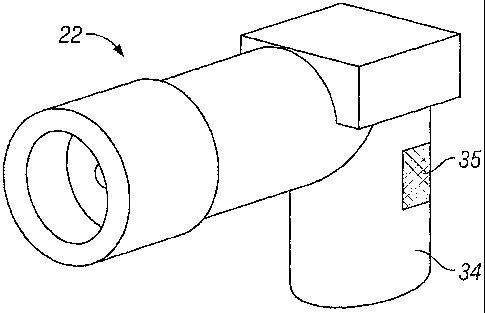
Referring to Fig. 3, the areas of differing reflectance on the spray head 22
can be seen.
Specifically, a portion of the neck 34 of the spray head 22 is coated with a
layer of dark
ink/paint/lacquer 35 which is of a lower reflectance than the remainder of the
neck 34 which is
uncoated.
In one embodiment of the invention, the detection means 38 can be operable to
detect the
presence of the spray head 22 and, further, detect whether there is at least
one area of low
reflectance and at least one area of higher reflectance on the spray head 22.
Firstly the detection means 38 may be operable to detect whether a refill 16
is loaded in the
device by interrogating the area normally occupied by a spray head 22 when a
refill is loaded
therein. Prior to permitting the actuation means 24 to activate, the detection
means 38 may
perform an initial interrogation of the location within the device normally
occupied by a spray head
of a refill when loaded into the device, if the detection means does not
detect any reflectance, or
a predetermined level of reflectance, this situation may be indicative of the
absence of a refill in
the device and the detection means 38 will prevent the actuation means from
activating, either
directly by communicating therewith or indirectly via a control unit.
Preferably the detection
means would interrogate an area normally occupied by lower portion of the neck
of the spray
head, as indicated by arrow 40 on Fig. 3B.
Should the presence of a refill 16 be detected, the detection means is further
configured to
interrogate further portions of the spray head 22. The detection means 38 may
be capable of
interrogating the spray head 22 by emitting radiation toward the spray head,
such as IR radiation,
17
CA 02700323 2010-03-19
WO 2009/037491 PCT/GB2008/003212
across one or more portions thereof, such as across a field of view as
indicated by arrow 42. The
detection means is capable of collecting reflected radiation such that the
amount of reflectance
collected can be attributed specifically or approximately or generally to a
portion or portions of the
spray head 22. Such attribution may permit the detection means 38 to directly,
or in combination
with the control unit (not shown), determine whether any areas of differing
reflectance are present
on the spray head 22.
Alternatively, the interrogation of the refill by the detection means 38 may
permit the detection
means to detect whether at least one differing level of reflected radiation is
detected without
attributing the detected level of reflectance to a specific section of the
spray head. Any such
detection may permit the detection means 38 to directly, or in combination
with the control unit
(not shown), determine whether any areas of differing reflectance are present
on the spray head
or in the area normally occupied thereby.
With either form of interrogation, if differing areas of reflectance are
detected the detection means
38 will communicate directly with the actuation means 26, or indirectly via a
control unit (not
shown), to permit the actuation means 26 to operate in accordance with the
user input command
to cause the spraying of fluid.
Conversely, if differing areas of reflectance are not detected, i.e. a
potentially dangerous refill has
been loaded into the device, the direct or indirect communication from the
detection means 38 will
call for the actuation means 26 to enter a dormant mode. During the dormant
mode the actuation
means 26 will not activate and not cause the spraying of fluid. The dormant
mode will be
maintained until a user initiates a resetting of the device. The resetting may
be facilitated by the
user loading a new refill into the device and/or the user operating a reset
button or the like.
However, if a vandal has intentionally loaded a potentially dangerous refill
and has reset the
device, once the detection means 38 scans the spray head 22 and fails to find
the required
reflectance, the actuation means 26 will again be placed in the dormant mode.
In an alternative embodiment, the detection means can be operable to detect
the presence of the
spray head 22 and detect whether there is at least one area of low reflectance
and at least one
area of higher reflectance on the spray head 22 only during the movement of
the spray head 22
following activation by the actuation means 26. This movement permits the
detection means 38
the opportunity to view a defined proportion of the spray head 22, thus fixing
the field of view of
the detection means (eg. as defined by arrow 42 in Fig. 3B). If during the
interrogation of the
spray head 22 differing areas of reflectance are detected by the detection
means 38, these
means will communicate with the actuation means 26, either directly or
indirectly, to permit the
18
CA 02700323 2010-03-19
WO 2009/037491 PCT/GB2008/003212
actuation means 26 to operate in accordance with the user input command to
cause the spraying
of fluid. Conversely, if differing areas of reflectance are not detected, i.e.
a potentially dangerous
refill has been loaded into the device, potentially to effect vandalism, the
communication from the
detection means 38 will call for the actuation means 26 to enter a dormant
mode, as discussed
above.
When a refill 16 has been loaded in the device 10 and the detection means 38
has been able to
distinguish between one area of lower reflectance and once area of higher
reflectance, the control
means or the like may initiate a counting mechanism. The counting mechanism
maybe
calibrated to permit a pre-determined number of actuations of the refill which
corresponds to the
quantity of fluid stored in a refill. The counting mechanism can be operable
in use, and after the
pre-determined number of actuations has been reached, to cause the device 10
to enter the
dormant mode, thus prevent further actuations of that refill, until a user
replaces the refill and/or
resets the device. The counting mechanism may automatically reset every time a
refill is loaded
into the device.
Figs. 3-6 illustrate various embodiments of refill spray heads. As mentioned,
Fig. 3 illustrates a
first embodiment wherein spray head has a generally L-shaped profile, wherein
the shorter part of
the L-shape, the neck portion 34, engages with the free end of the valve stem.
The angle
between the part of the spray head connected to the valve stem and the part of
the spray head
possessing the exit orifice is illustrated as being substantially 90 , however
this angle may be
between 60-120 , the key aspect is that the exit orifice directs the spray of
fluid through the
opening 14 and away from the housing of the device. The neck portion 34 of the
spray head 22
is coated with a layer of dark ink/paint/lacquer 35 which is of a lower
reflectance than the
remainder of the neck 34 which is uncoated. Ideally the layer of dark is
substantially black and
the rest of the spray head, including the remainder of the neck portion 34, is
substantially white.
In Fig. 3 the layer of dark ink/paint/lacquer is coated on to the spray head
but this may be applied
or incorporated by any suitable means, such as by application of a label,
printing, engraving or
the spray head could be manufactured from two or more component parts which
are fixed
together.
In Figs. 4 & 5 the spray head 22 is shaped to deflect any interrogation away
from the detection
means 38 of the device. The detection means for use with the spray head shown
in Fig. 4 will
have a fixed position and a limited filed of view of the spray head to
interrogate as indicated by
arrow 46. Arrow 48 shows the field of view detection means may detect to
determine whether a
19
CA 02700323 2010-03-19
WO 2009/037491 PCT/GB2008/003212
refill 16 is loaded in the device by interrogating the area normally occupied
by a spray head 22
when a refill is loaded therein.
The detection means is operable to emit interrogation in the direction of
arrow 44 and a V-shaped
portion 50 of the spray head is shaped to substantially deflect the detector
means' interrogation
not back toward the detection means but away therefrom in the direction of
arrows 44'. In
contrast the neck portion 4 of the spray head is shaped to substantially
reflect the interrogation
back toward the detection means to be collected thereby. The deflection of
interrogation 44 by the
V-shaped portion 50 may be shaped to deflect the interrogation at 901 away
from the normal or
>900 away from the normal.
The spray head illustrated in Fig. 5 is similar to that as shown in Fig. 4
save for the 90 orientation
of the V-shaped potion 54, thus causing, in use, a different direction of
deflection of interrogation
52 in the direction of arrows 52'.
In Fig. 6 a yet further alternative arrangement of the spray head is
illustrated could be provided
with a portion cutaway to provide a greater distance for reflected
interrogation to travel, in use, to
a detection means in comparison to the distance for reflected interrogation to
travel from a non-
cutaway portion of the spray head. The detection means for use with the spray
head shown in
Fig. 6 will have a fixed position and a limited filed of view of the spray
head to interrogate as
indicated by arrow 60. Arrow 58 shows the field of view detection means may
detect to
determine whether a refill is loaded in the device by interrogating the area
normally occupied by a
spray head 22 when a refill is loaded therein. In this arrangement the
interrogation, shown
byarrows 62,62', emitted from the detection means should be tuned such that it
is capable of
travelling the distance between the non-cutaway portion of the spray head and
back again after
reflection, however, should that distance be increased the radiation is less
capable of travelling
the increased distance. Due to the tuning of the radiation, the amount of
radiation being collected
by the detection means along arrow 62 would be less than from the radiation
travelling along
arrow 62', this difference in reflectance being detectable by the detection
means, thus indicating
two areas of differing reflectance.
All of the features disclosed in this specification (including any
accompanying claims, abstract
and drawings), and/or all of the steps of any method or process so disclosed,
may be combined
in any combination, except combinations where at least some of such features
and/or steps are
mutually exclusive. Each feature disclosed in this specification (including
any accompanying
claims, abstract and drawings) may be replaced by alternative features serving
the same,
equivalent or similar purpose, unless expressly stated otherwise. Thus, unless
expressly stated
CA 02700323 2010-03-19
WO 2009/037491 PCT/GB2008/003212
otherwise, each feature disclosed is one example only of a generic series of
equivalent or similar
features. The invention is not restricted to the details of the foregoing
embodiment(s). The
invention extends to any novel one, or any novel combination, of the features
disclosed in this
specification (including any accompanying claims, abstract and drawings), or
to any novel one, or
any novel combination, of the steps of any method or process so disclosed.
21