Note: Descriptions are shown in the official language in which they were submitted.
CA 02701059 2010-03-26
1
DESCRIPTION
PIERCING AND ROLLING PLUG, METHOD OF REGENERATING SUCH PIERCING
AND ROLLING PLUG, AND EQUIPMENT LINE FOR REGENERATING SUCH
PIERCING AND ROLLING PLUG
TECHNICAL FIELD
[0001]
The present invention relates to a piercing and rolling
plug (hereinafter also referred to as a "plug" for short) used
repeatedly on a piercing and rolling mill in the manufacture
of seamless steel pipes, to a method of regenerating such a
plug, and to an equipment line for regenerating such a plug.
BACKGROUND ART
[0002]
The Mannesmann pipe making process is a widely employed
process for producing seamless steel pipes by hot working. In
the Mannesmann pipe making process, a round billet heated to
a predetermined temperature is fed to a piercing and rolling
mill (piercer) and the axial central portion of the round billet
is pierced, whereby a hollow blank pipe called "hollow shell"
is obtained.
[0003]
The hollow shell, either as it is or after diameter
expansion and wall thinning, if necessary, by passing through
an elongator of the same configuration as the above-mentioned
piercing and rolling mill, is fed to a following elongating
rolling mill such as a plug mill or mandrel mill for elongating
and rolling. Thereafter, the resulting pipe is passed through
a stretch reducer, a reeler, a sizer, etc. for polishing, shape
adjustment and sizing; a final product seamless steel pipe is
thus produced.
[0004]
In piercing and rolling by the piercing and rolling mill,
a bullet-shaped plug is used as a piercing tool. This plug
is mounted on the front end of a core bar or mandrel and used
for piercing the billet heated to a high temperature of about
CA 02701059 2010-03-26
2
1200 C, so that it is exposed to high-temperature and
high-contact-pressure conditions. Therefore, an oxide scale
film is formed on the plug surface to protect the plug base
metal. The scale film shields the plug against heat from the
billet and at the same time plays a role in preventing seizure
by the billet.
[0005]
The scale film on the plug surface is generally formed
by subjecting the plug made of a tool steel for how working
to heat treatment at a high temperature of about 900 C to 1000 C
for several to several tens of hours.
[0006]
In recent years, the demand for seamless steel pipes has
shown a trend toward a marked increase and, in particular, the
increase in demand for seamless steel pipes for use in severe
environments is significant. Seamless steel pipes made of such
a high alloy steel species as stainless steel, Ni-based alloy
steel or high-Cr-containing steel with a Cr content of 9% or
higher are suited for use in severe environments.
[0007]
When a scale film coated plug is used for piercing and
rolling in the production of high alloy steel seamless pipes,
a billet high in deformation resistance is to be pierced and
therefore the scale film on the plug is susceptible to wear
and/or peeling off. Once the scale film on the plug has been
worn out or peeled off, the heat-shielding effect diminishes
and the temperature of the plug base metal rises, and the plug
may possibly be damaged due to heat-related metal wastage.
[0008]
When a scale film coated plug is used for piercing and
rolling in the process of producing high alloy steel seamless
pipes, the scale film is generally worn out in several rolling
passes and, thus, the life thereof is very short.
[0009]
If piercing and rolling is continued using a plug with
a damaged scale film, seizure failure will occur due to the
CA 02701059 2010-03-26
3
direct contact between the plug base metal and the billet surface
and, at the same time, flaws will be developed on the inside
surface of the hollow shell, impairing the quality of the product .
[0010]
Therefore, in the production of high alloy steel seamless
pipes, plug replacement is to be made frequently and, as a result,
the production efficiency of the piercing and rolling mill
declines. In particular, in the current situation in which
efficient production of seamless steel pipes is aimed at and
the continuous operation of the Mannesmann pipe making equipment
reaches an advanced state, a reduction in production efficiency
of the piercing and rolling mill exerts an influence on the
efficiency of the whole process of production of seamless steel
pipes.
[0011]
For regenerating and reuse, the plug once used for piercing
and rolling and demounted from the mandrel, it is necessary
to re-form the scale film; however, lengthy time and a number
of steps are required for the necessary heat treatment to that
end. Accordingly, it is necessary to keep an immense number
of plugs so that even when plug replacement is made with high
frequency, any shortage of plugs may not occur to circumvent
the decrease in production efficiency of the piercing and rolling
mill.
[0012]
In view of such situation, various investigations have
so far been made to prolong the plug lifetime and thereby reduce,
as far as possible, the number of plugs to be kept prepared.
For example, Japanese Patent Publication No. 04-8498
(hereinafter referred to as "Document 1") proposes a plug base
metal increased in high-temperature strength by reducing the
Cr content and adding Mo, W and/or the like as well as a plug
with an oxide scale excellent in adhesiveness as being formed
on and attached to the surface of the plug.
[0013]
The plug proposed in Document 1 has a drawback in that
CA 02701059 2010-03-26
4
when the billet piercing length is increased, the plug base
metal becomes insufficient in both high-temperature strength
and scale film adhesiveness, and hence a satisfactorily long
lifetime cannot be secured.
[0014]
Japanese Patent Application Publication No. 04-74848
(hereinafter referred to as "Document 2") and Japanese Patent
Application Publication No. 04-270003 (hereinafter referred
to as "Document 3") propose plugs for which a plug base metal
having a chemical composition suited for improvements in
high-temperature deformation resistance and crack resistance
is employed and on the surface of which an oxide scale is formed.
However, the plugs proposed in these Documents 2 and 3 have
a drawback in that the scale film in the plug tip portion, where
the contact pressure is the highest and the temperature increases
in piercing, is melted and loses the heat-shielding ability
and wear resistance, with the result that the plug tip readily
undergoes damages and/or deformation due to melting-related
metal wastage.
[0015]
Japanese Patent Publication No. 64-7147 (hereinafter
referred to as "Document 4") proposes a plug for which a plug
base metal containing Cr and Cu as added thereto is used and
on the surface of which a scale film is formed. However, the
plug proposed in Document 4 also has a drawback in that the
plug tip readily undergoes damages and/or deformation due to
melting-related metal wastage on the occasion of piercing.
[0016]
The plugs proposed in the above-cited Documents 1-4, the
plug base metalchemicalcompositionsofwhich have been adjusted,
in any case, when applied to piercing and rolling in high alloy
steel seamless pipe manufacture, cannot be expected to show
satisfactorily prolonged lifetime through such plug base metal
composition designing alone.
[0017]
Further, the plugs proposed in the above Documents 1-4,
CA 02701059 2010-03-26
when repeatedly used for piercing and rolling, all require a
long period of heat treatment for scale film regeneration.
Therefore, investigations have so far been made to increase
the plug lifetime by changing a plug surface scale film with
other than the oxide scale.
[0018]
For example, Japanese Patent Application Publication No.
10-180315 (hereinafter referred to as "Document 5") proposes
a plug increased in high-temperature bending strength by
partially replacing the plug surface with ceramic material such
as SiC, A1203r ZrO2 or Si3N4 in lieu of the oxide scale. Japanese
Patent Publication No. 59-13924 (hereinafter referred to as
"Document 6") proposes a plug with a film formed on the surface
thereof by plasma spraying of an Fe oxide powder.
[0019]
However, the plug proposed in Document 5 is susceptible
to damaging of the ceramic portion due to the impact on the
occasion of piercing and is thus required to be handled carefully
on the occasion of plug replacement and handling. Furthermore,
the ceramic-constituted plug itself is expensive and difficult
to regenerate. Further, the plug proposed in Document 6
requires a large-scale apparatus for plasma spraying of powders
for the preparation and regeneration of the plug, and hence
requires huge costs.
DISCLOUSRE OF INVENTION
[0020]
As mentioned hereinabove, investigations have so far been
made to prolong a plug lifetime so that the production efficiency
in piercing and rolling may not be reduced. However, the plug
base metal composition designing alone cannot be expected to
bring about a sufficient extent of prolongation of the plug
lifetime when the plug is used in piercing and rolling in high
alloy steel seamless pipe production.
[0021]
Further, in the case of reusing the plug in piercing and
rolling, a long period of heat treatment is required for scale
CA 02701059 2010-03-26
6
film regeneration. Therefore, investigations have so far been
made in an attempt to constitute the surface film with a ceramic
material in lieu of the oxide scale or form a film by plasma
spraying of iron oxide powders. The measures attempted in each
case, however, cannot be effective for the prolongation of the
plug lifetime.
[0022]
The present invention, which has been made in view of
the problems discussed above, has an object to provide a piercing
and rolling plug which is long in plug lifetime and, in recycled
use thereof, can be regenerated at low cost and in a short period
of time, and a method of regenerating of such piercing and rolling
plug as well as an equipment line for piercing and rolling plug
regeneration in which such plug can be regenerated in an equipment
line (on-line) composed of a series of apparatus for recycling
of the plug.
[0023]
To accomplish the above object, the present inventors
made intensive investigations in an attempt to prolong the
lifetime of the plug in the use thereof for piercing and rolling
in seamless steel pipe production and realize the regeneration
thereof at low cost and in a short period of time for smooth
recycled use and, as a result, they have completed the present
invention.
[0024]
Essentially, the present invention provides (1) a
piercing and rolling plug, (2) a method of regenerating the
piercing and rolling plug and (3) an equipment line for
regenerating the piercing and rolling plug, each defined below.
[0025]
(1) A piercing and rolling plug for recycl ed use in a piercing
and rolling mill to be employed in seamless steel pipe production
is characterized in that the plug has a film composed of oxides
and Fe as formed on a shot-blasted plug base metal surface by
electric arc spraying using an iron wire.
[0026]
CA 02701059 2010-03-26
7
In the plug according to (1) , the proportion of the regions
occupied by the oxides in the above-mentioned film is preferably
55-80%. It is also preferred that the proportion of the regions
occupied by the oxides in the film be higher on the surface
layer side thereof than on the base metal side thereof; in this
case, the proportion of the regions occupied by the oxides in
the film is preferably not more than 40% in the adjacent portion
to the base metal and 55-80% in the surface layer portion. The
plug is preferably bullet-like in shape and the thickness of
the film in the tip portion is preferably thicker than that
in the cylindrical portion. Further, it is preferred that the
surface of the film has a lubricant applied thereto. The iron
wire preferably contains W.
[0027]
(2) A method of regenerating the piercing and rolling plug
according to (1) for recycled use thereof is characterized in
that the surface of the plug is subjected to shot blasting to
remove the film as used for piercing and rolling and a film
composed of oxides and Fe is then formed by electric arc spraying
using an iron wire.
[0028]
In the regeneration method according to (2), the removal
of the film by shot blasting and the film formation by electric
arc spraying are preferably carried out only in the tip portion
of the bullet-shaped plug.
[0029]
(3) An equipment line for regenerating a plug for recycled
use on a piercing and rolling mill to be employed in seamless
steel pipe production is characterized in that the equipment
line comprises: a mandrel delivery and receipt apparatus for
delivering a mandrel with the above-mentioned plug being mounted
thereon and recovering the mandrel after use in piercing and
rolling; a plug exchange apparatus for receiving the mandrel
after use in piercing and rolling from the mandrel delivery
and receipt apparatus and delivering the mandrel to the mandrel
delivery and receipt apparatus after replacement of the plug
CA 02701059 2010-03-26
8
as being used in the piercing and rolling with the regenerated
plug ; a shot blasting apparatus for receiving the plug as being
used in piercing and rolling from the plug exchange apparatus
and subjecting the surface of the plug as being used in piercing
and rolling to shot blasting; and an electric arc spraying
apparatus for receiving the plug treated in the shot blasting
apparatus, regenerating the plug by electric arc spraying using
an iron wire for formation of a film composed of oxides and
Fe on the surface thereof and delivering the thus-regenerated
plug to the plug exchange apparatus, where said apparatuses
are disposed in the above order to make the equipment line,
and, in such line, the plug as being used for piercing and rolling
is successively replaced with the regenerated plug, mounted
on the mandrel, and then fed repeatedly to the piercing and
rolling mill.
[0030]
The regeneration equipment line according to (3)
preferably further comprises a lubricant spraying apparatus
for applying a lubricant on the surface of the regenerated plug
in the route from the mandrel delivery and receipt apparatus
to the piercing and rolling mill, where delivering the mandrel
with the regenerated plug mounted thereon is made.
[0031]
The piercing and rolling plug according to the present
invention has a film formed on the plug surface and composed
of oxides and Fe and, therefore, is excellent in heat-shielding
and seizure-preventing abilities and at the same time has a
prolonged lifetime and, in addition, since the film is formed
by electric arc spraying, the plug can be prepared and regenerated
at low cost and in a short period of time.
[0032]
According to the method of regenerating the piercing and
rolling plug according to the present invention, the plug as
being used in piercing and rolling is subjected to shot blasting
and electric arc spraying in turn and a film composed of oxides
and Fe is re-formed on the plug surface and, therefore, the
CA 02701059 2010-03-26
9
plug can be regenerated at low cost and in a short period of
time.
[0033]
Further, the equipment line for regenerating the piercing
and rolling plug according to the present invention can be
realized as an automated regeneration line for plug regeneration
and replacement in a short period of time for recycled use of
a series of plugs, thus enabling on-line plug regeneration
without causing any adverse effect on the efficiency of the
seamless steel pipe production process as a whole.
BRIEF DESCRIPTION OF THE DRAWINGS
[0034]
Fig. 1 is a representation of the results of X ray analysis
measurements of plug surface films as a function of the electric
arc spraying distance.
Fig. 2 is representations of the sectional
microstructures of plug surface films as a function of the
electric arc spraying distance.
Fig. 3 is a representation of the correlation between
the proportion of oxides in the plug film and the adhesion
strength of the film.
Fig. 4 is a representation of the correlation between
the proportion of oxides in the plug film and the film wear
amount.
Fig. 5 is a representation of the correlation between
the proportion of oxides in the plug film and the number of
successive piercing and rolling runs (number of passes).
Fig. 6isa representation of the sectionalmicrostructure
of a plug surface film obtained by electric arc spraying while
gradually increasing the spraying distance.
Fig. 7 is a representation of the relation between a W
content and a piercing efficiency for plugs with a film formed
thereon by electric arc spraying using a W-containing iron wire.
Fig. 8 is a representation of the relation between a
piercing efficiency and an extent of plug tip deformation for
plugs with a film formed thereon by electric arc spaying using
CA 02701059 2010-03-26
a W-containing iron wire.
Fig. 9 is a schematic sectional representation of the
tip portion and the vicinity thereof of a plug with a film formed
by electric arc spraying, as being observed after 10 passes
of piercing.
Fig. 10 is a representation of the correlation between
the number of successive piercing passes and the thickness of
the film remaining on the cylindrical portion of the plug.
Fig. 11 is a schematic representation of the whole
configuration of a regeneration equipment line for recycled
use of the piercing and rolling plug according to the present
invention.
Fig. 12 is a side view illustrating the whole configuration
of a plug exchange apparatus.
Figs. 13(a) to 13(f) are sectional representations of
essential parts for illustrating exemplary plug mounting and
demounting mechanisms in the plug exchange apparatus.
Fig. 14 is a side view illustrating the whole configuration
of a shot blasting apparatus.
Fig. 15 is a side view illustrating the whole configuration
of an electric arc spraying apparatus.
Fig. 16 is a schematic representation of the whole
configuration of a plug regeneration equipment line where a
lubricant spraying apparatus is disposed.
Fig. 17 is a side view illustrating the whole configuration
of the lubricant spraying apparatus.
Fig. 18 is a schematic representation of the whole
configuration of another plug regeneration equipment line where
the lubricant spraying apparatus is disposed.
BEST MODES FOR CARRYING OUT THE INVENTION
[0035]
The piercing and rolling plug according to the present
invention is characterized in that, in film formation on the
plug base metal surface, a film composed of oxides, such as
Fe304 and FeO, and Fe (metal) is formed on the plug base metal
surface by electric arc spraying onto the plug base metal surface
CA 02701059 2010-03-26
11
using an iron wire whose main component is Fe.
[0036]
By constructing such structure, it becomes possible to
form a film, on the surface of a newly prepared plug or a plug
to be regenerated, by electric arc spraying in a very short
period of time as compared with the conventional cases of scale
film formation by heat treatment. In addition, the electric
arc spraying apparatus can have a much simpler configuration
as compared with the prior art plasma spraying apparatus.
Furthermore, the iron wire which is the electric arc spraying
material can be obtained at a lower cost as compared with the
conventional plasma spraying material powder.
[0037]
The film mixedly composed of oxides and Fe as formed on
the surface of the piercing and rolling plug according to the
present invention is excellent in heat-shielding and
seizure-inhibiting abilities. In the following, the
characteristic features of the piercing and rolling plug
according to the present invention are described.
[0038]
Fig. 1 shows the results of X ray analysis measurements
of plug surface films as a function of the electric arc spraying
distance. Fig. 2 shows the sectional microstructures of plug
surface films as a function of the electric arc spraying distance.
The spraying distance is the distance from the spraying nozzle
of the electric arc spraying apparatus to the surface of the
plug base metal, which is the target to be coated. In Fig.
1 and Fig. 2, there are shown the measurement results and
sectional microstructures of the films formed by electric arc
spraying from the respective spraying distances of 200 mm, 400
mm, 600 mm, 800 mm, 1000 mm, 1200 mm and 1400 mm.
[0039]
Fig. 1 shows that, in the films formed on the plug base
metal surface by electric arc spraying, the content of the oxides,
Fe304 and FeO, increases and the Fe content decreases with the
increase in spraying distance. This is due to the fact that
CA 02701059 2010-03-26
12
the oxidation of the molten spraying material (Fe) sprayed from
the spraying nozzle proceeds as the spraying distance increases.
[0040]
In the sectional views of the films as shown in Fig. 2,
each region observed with a pale gray color represents Fe, each
region observed as a dark gray color represents an oxide, and
each region observed as a black color represents a void, as
so indicated in the views. As is seen from the same view, when
the spraying distance is 200 mm, for example, oxides occupy
20%-30% of the whole region of the film, with the remaining
70%-80% of the whole region being occupied by Fe. When the
spraying distance is 1000 mm, oxides occupy about 80% of the
region of the film, with the remaining about 20% of the region
being occupied by Fe. The microstructures in Fig. 2 also
indicate that as the spraying distance is increased, the
proportion of oxides increases while the amount of Fe decreases.
[0041]
In such a manner, the proportion of regions occupied by
oxides in the film (hereinafter referred to as "oxide ratio")
varies depending on the spraying distance. Therefore, by
adjusting the spraying distance, it is possible to control the
oxide ratio in the film.
[0042]
Fig. 3 shows the correlation between the oxide ratio in
the plug f ilm and the adhesion strength of the f ilm. The adhesion
strength of the film is indicative of performance in tightness
and close adhesion with the plug base metal surface and serves
as an indicator of the peel-off resistance in piercing and rolling.
Thus, when the adhesive strength is high, the film is hardly
peeled off and, when the adhesion strength is low, the film
iseasilypeeledoff. AsshowninFig. 3, the peel-off resistance
of the film decreases as the oxide ratio in the film increases
and, at oxide ratios exceeding 80%, it decreases rapidly.
[0043]
Fig. 4 shows the correlation between the oxide ratio in
the plug film and the film wear amount. The film wear amount
CA 02701059 2010-03-26
13
represents the decrease in weight after 1600 repetitions of
scrubbing of the surface film and serves as an indicator of
the wear resistance in piercing and rolling. Thus, when the
wear amount is small, the film is hardly worn out and, when
the wear amount is great, the film is easily worn out. As shown
in Fig. 4, the wear resistance of the film decreases as the
oxide ratio in the film increases and, at oxide ratios exceeding
80%, it decreases rapidly.
[0044]
The decreases in the peel-off resistance and wear
resistance of the film with the increase in the oxide ratio
in the film, as shown in Fig. 3 and Fig. 4, are attributed to
the decrease of Fe (metal) that is interposed between adjacent
discrete oxides to thereby serve for bonding them together.
[0045]
While the peel-off resistance and wear resistance of the
film are secured at higher level as the oxide ratio in the film
decreases, as seen from Fig. 3 and Fig. 4, an excessively low
oxide ratio level means that Fe occupies the major part of the
film, with the result that the thermal conductivity becomes
relatively high but the heat-shielding ability declines.
Therefore, the plug tip portion becomes readily susceptible
to damaging and deformation due to melting-related wastage on
the occasion of piercing and rolling.
[0046]
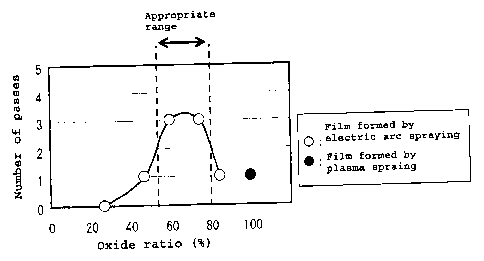
Fig. 5 shows the correlation between the oxide ratio in
the plug film and the number of successive piercing and rolling
runs (number of passes). In carrying out demonstration testing,
from which the results shown in that view had been derived,
test sample plugs were prepared using a hot working tool steel
as prescribed in JIS and an about 400-pm-thick film was formed
on the surface of each plug base metal by electric arc spraying
using an iron wire.
[0047]
On the occasion of electric arc spraying, the position
of the spraying nozzle was adjusted to the corresponding spraying
CA 02701059 2010-03-26
14
distance so that the oxide ratio in the film can be 25, 45,
60, 75 or 85%. Further, for comparison, a film was formed on
the plug base metal surface by plasma spraying of a Fe304 powder.
This plasma-sprayed plug corresponds to the plug proposed in
the above-cited Document 6 and the film is composed of 100%
oxides.
[0048]
Using the test sample plugs obtained, tests were carried
out in which workpieces were successively pierced and rolled.
Used as the workpieces were round billets each having an outside
diameter of 70 mm and a length of 1000 mm and made of SUS304
(austenitic stainless steel defined in JIS) as being a high
alloy steel. These workpieces were heated to 1200 C and then
subjected to piercing testing, using the above-mentioned test
sample plugs, to produce hollow shells each with an outside
diameter of 74 mm, a wall thickness of 8.6 mm and a length of
2200 mm.
[0049]
In this test, for each test sample plug, the appearance
thereof was examined after each piercing and rolling pass, and
the plug lifetime was evaluated and determined in terms of the
number of passes at the time that damaging or deformation due
to melting-related metal wastage was found in the plug tip
portion, namely the maximum number of passes in which piercing
and rolling could be successfully successively repeated (number
of successive piercing and rolling passes).
[0050]
As outlined circles in Fig. 5 indicate, the number of
successive piercing passes was 0 (zero) in the case of the plug
with the oxide ratio in the film being 25%, the number of
successive piercing passes was 1 in the case of the plug with
the oxide ratio being 45% or 85%, and the number of successive
piercing passes was 3 in the case of the plug with the oxide
ratio being 60% or 75%.
[0051]
In the case of the plasma-sprayed plug for comparison,
CA 02701059 2010-03-26
the number of successive piercing passes was 1, as indicated
by a solid circle in Fig. 5. Further, in the case of the plug
with the oxide ratio in the film being 25% or 45%, the occurrence
of damaging or deformation due to melting-related metal wastage
was observed at the plug tip portion.
[0052]
From the results shown in Fig. 5, it is evident that those
plugs which have a film formed by electric arc spraying with
the oxide ratio therein as adj usted to 55-80% have a plug lifetime
at least twice that of the plasma-sprayed plug and, further,
that those plugs which have a film with the oxide ratio therein
as adjusted to 60-75% have a plug lifetime at least three times
that of the plasma-sprayed plug.
[0053]
Therefore, when the oxide ratio in the film is adjusted
to 55-80%, the plug according to the present invention for use
in piercing and rolling in the production of high alloy steel
seamless pipes, shows a longer lifetime as compared with the
prior art plasma-sprayed plug. Further, from the viewpoint
of further prolongation of the plug lifetime, it is preferred
that the oxide ratio in the film be adjusted to 60-75%.
[0054]
Next, in relation to the effects of the oxide ratio in
the film as revealed by the results shown in Fig. 5, a further
effectiveness aspect is now discussed. In the case of the plugs
used in the test, from which the results shown in Fig. 5 were
derived, the films were formed by carrying out electric arc
spraying in a condition such that the spraying distance was
kept constant so as to obtain a film having a uniform oxide
ratio over the whole region from an adjacent portion to the
base metal to the surface layer portion. In this regard, a further
study was made this time using plugs with a film formed by electric
arc spraying while the spraying distance was gradually increased
so that the oxide ratio in the film might gradually increase
toward the surface layer side.
[0055]
CA 02701059 2010-03-26
16
Thus, in the film formation, the electric arc spraying
was started in a state such that the spraying nozzle was closest
to the plug base metal surface, namely in a state such that
the spraying distance was short, the spraying nozzle was then
gradually distanced from that surface, and the electric arc
spraying was completed in a state such that the spraying distance
became long. In this way, there was formed on the plug base
metal surface a film with the oxide ratio gradually increasing
toward the surface layer side. In this film, the oxide ratio
was low in the adjacent portion to the base metal and the oxide
ratio was high in the surface layer portion.
[0056]
Fig. 6 shows the sectional microstructure of the plug
surface film obtained by electric arc spraying while gradually
increasing the spraying distance. In the cross-section of the
film as shown in that view, likewise in Fig. 2 referred to
hereinabove, each region observed asa pale gray color represents
Fe, each region observed as a dark gray color represents an
oxide, and each region observed as a black color represents
a void. As shown in Fig. 6, the film formed on the plug base
metal surface is low in oxide ratio in the adjacent portion
to the base metal and the surface layer portion shows an increased
oxide ratio.
[0057]
Using test sample plugs having such a film, tests as the
piercing test mentioned above were carried out likewise. The
evaluation was made based on the plug lifetime expressed in
terms of the above-mentioned number of successive piercing and
rolling runs (number of passes) . For comparison, a plug with
a film uniform in oxide ratio in the whole region as formed
on the plug base metal surface by electric arc spraying while
keeping a constant spraying distance was also tested in the
same manner. The results of the test are shown below in Table
1.
[0058]
[Table 1]
CA 02701059 2010-03-26
17
Table 1
Electric arc spraying Number of
Test conditions successive
No. Spraying distance piercing
passes
1 Constant at 1000 mm 2 passes
2 Varied from 200 mm to 4 1000 mm passes
3 Varied from 400 mm to 3 passes
1000 mm
4 Varied from 500 mm to 2 1000 mm passes
[0059]
As shown in the table, the plug of Test No. 1 was provided
with a film by electric arc spraying from a constant spraying
distance at 1000 mm, and the oxide ratio in the film was uniformly
about 80% throughout the whole range of the film.
[0060]
On the other hand, the plug of Test No. 2 was provided
with a film by electric arc spraying while gradually varying
the spraying distance from 200 mm to 1000 mm, the plug of Test
No. 3 was provided with a film by electric arc spraying while
gradually varying the spraying distance from 400 mm to 1000
mm, and the plug of Test No. 4 was provided with a film by electric
arc spraying while gradually varying the spraying distance from
500 mm to 1000 mm. As a result, in the film of the plug of
Test No. 2, the oxide ratio was about 25% in the adjacent portion
to the base metal and about 80% in the surface layer portion;
in the film of the plug of Test No. 3, the oxide ratio was about
40% in the adjacent portion to the base metal and about 80%
in the surface layer portion; and in the film of the plug of
Test No. 4, the oxide ratio was about 50% in the adjacent portion
to the base metal and about 80% in the surface layer portion.
[0061]
The plugs of Test Nos. 1-4 all had a film thickness of
about 400 pm.
[0062]
CA 02701059 2010-03-26
18
As shown in Table 1, for the plug of Test No. 1 with a
uniformoxide ratio in the film, the number of successive piercing
passes was 2. On the other hand, among the plugs of Test Nos.
2-4 in which the oxide ratio in the film was higher on the surface
layer side than on the base metal side, the number of successive
piercing passes was 4 in the case of the plug of Test No. 2,
and the number of successive piercing passes was 3 in the case
of the plug of Test No. 3 and, in each case, the number of
successive piercing passes was bigger as compared with the plug
of Test No. 1. In the case of the plug of Test No. 4, the number
of successive piercing passes was 2 and thus was equivalent
to the number of successive piercing passes for the plug of
Test No. 1.
[0063]
From the results shown in Table 1, it is evident that:
the plugs having a film in which the oxide ratio is higher on
the surface layer side than on the base metal side are comparable
in plug lifetime to or longer than the plugs having a film uniform
in oxide ratio throughout the whole region thereof; and further,
the plugs with a film as having the oxide ratio of 40% or less
in the adjacent portion to the base metal have a prolonged plug
lifetime. This is due to the fact that the adjacent portion
of the film to the base metal is low in oxide ratio and therefore
rich in Fe (metal), so that the adhesion of the film to the
plug base metal is fortified and, as a result, the stress imposed
is relaxed and the film is hardly peeled off.
[0064]
Accordingly, it is preferred that the oxide ratio in the
film of the plug of the present invention be higher on the surface
layer side than on the base metal side and, in particular, it
is more preferable that the oxide ratio in the adjacent portion
to the base metal be not less than 40% and the oxide ratio in
the surface layer portion be 55-80%.
[0065]
Now, the thickness aspect of the film formed on the plug
base metal surface is discussed. While the plugs each tested
CA 02701059 2010-03-26
19
above had a bullet-like external shape with a uniformly thick
film being formed in the whole range from the cylindrical portion
of the plug to the tip portion, the film thickness in the
cylindrical portion and that in the tip portion were varied
now so as to identify the influences of the film thickness in
the cylindrical portion and that in the tip portion. The
thus-prepared test sample plugs with such a film were tested
in the same manner as in the piercing test mentioned above.
The evaluation was made based on the plug lifetime expressed
in terms of the above-mentioned number of successive piercing
and rolling runs (number of passes), likewise in the evaluation
results as shown in Table 1. The test results obtained are
shown below in Table 2.
[0066]
[Table 2]
Table 2
Film thickness Number of
Test successive
No. Cylindrical Tip piercing
portion portion passes
11 400pm 400pm 4 passes
12 400pm 600pm 5 passes
13 400pm 800pm 6 passes
14 600pm 800pm 6 passes
15 800pm 800pm 1 pass
16 400pm 1200pm 10 passes
[0067]
As shown in the above table, the plug of Test No. 11 was
provided with a film having a uniform thickness of about 400
pm from the cylindrical portion to the tip portion. The plug
of Test No. 12 was provided with a film having a thickness of
about 400 pm in the cylindrical portion and a thickness of about
600 pm in the tip portion, the plug of Test No. 13 was provided
with a film having a thickness of about 400 pm in the cylindrical
portion and a thickness of about 800 pm in the tip portion,
and the plug of Test No. 14 was provided with a film having
CA 02701059 2010-03-26
a thickness of about 600 pm in the cylindrical portion and a
thickness of about 800 pm in the tip portion. The plug of Test
No. 15 was provided with a film having a uniform thickness of
about 800 pm in the whole range from the cylindrical portion
to the tip portion. The plug of Test No. 16 was provided with
a film having a thickness of about 400 pm, like the plugs of
Test Nos. 11-13, in the cylindrical portion and a thickness
greater than in any of the other plugs, namely about 1200 pm,
in the tip portion.
[0068]
In any of plugs of Test Nos. 11-16, the film was formed
by electric arc spraying while varying the spraying distance
from 200 mm to 1000 mm and, therefore, the oxide ratio in the
film was higher on the surface layer side than on the base metal
side.
[0069]
As shown in Table 2, the number of successive piercing
passes was 4 with the plug of Test No. 11 small and uniform
in film thickness in the whole range. With the plugs of Test
Nos. 12, 13, 14 and 16 in which the film was heavier in the
tip portion than in the cylindrical portion, the numbers of
successive piercing passes were 5, 6, 6 and 10, respectively,
and the number of successive piercing passes increased with
the increase in film thickness in the plug tip portion. With
the plug of Test No. 15 great and uniform in film thickness
in the whole range, the film in cylindrical portion of the plug
was peeled off after a single piercing pass and, thus, the number
of successive piercing passes was only 1.
[0070]
From the results shown in Table 2, it is evident that
the heavier the film thickness in the plug tip portion is, the
more prolonged the plug lifetime is. Further, when the film
thickness in the cylindrical portion of the plug is excessively
heavy, peeling off of the film occurs on the occasion of piercing
and the plug lifetime is shortened thereby. Therefore, it is
preferred that the film thickness be heavier in the tip portion
CA 02701059 2010-03-26
21
than in the cylindrical portion and that the film thickness
in the cylindrical portion of the plug be lighter than 800 pm,
more preferably within the range of 400 pm to 600 pm.
[0071]
Meanwhile, on the occasion of piercing and rolling of
a billet on the piercing and rolling mill, the billet heated
to a high temperature is fed in an axial direction thereof at
a constant rate while the billet is rotated by means of a plurality
of revolving rolls (piercer rolls) disposed around the billet.
In front of the driven billet, there is disposed the plug along
an axial line of the billet and the front face of the billet
is pressed against the plug tip, whereupon the piercing and
rolling is started. When the billet is fed until the plug
completely goes through the billet, the piercing and rolling
end.
[0072]
On that occasion, the velocity at which the billet is
fed in an axial direction thereof (hereinafter referred to as
"feeding velocity") is determined by the number of revolutions
of the piercer rolls. However, the actual feeding velocity
during piercing becomes slower as compared with the theoretical
feeding velocity calculated from the set number of revolutions
of the piercer rolls due to the influences by the frictional
resistance between the plug and the billet in contact with each
other and the like. The velocity ratio (= (actual feeding
velocity)/(theoretical feeding velocity) x 100 [%]) is
generally referred to as "piercing efficiency".
[0073]
When the piercing efficiency is high, not only the
production efficiency of the piercing and rolling mill is
improved but also the time of contact between the plug and the
billet is shortened, hence prolongation of the plug lifetime
can be expected. Therefore, in piercing and rolling, it is
very important to improve the piercing efficiency.
[0074]
Therefore, a discussion is now held about the improvement
CA 02701059 2010-03-26
22
of the piercing efficiency by means of the plugs mentioned above.
First, test sample plugs were prepared by forming a film on
the plug surface by electric arc spraying and then forming thereon
a layer of a lubricant commonly used in high temperature
environments, and they were tested in the same manner as in
the piercing test mentioned above. For comparison, plugs having
no lubricant layer were also subjected to the same test. The
evaluation was performed based on the average piercing
efficiency calculated from the piercing efficiency data in the
respective passes until the end of the lifetime of the plug.
The test results thus obtained are shown below in Table 3.
[0075]
[Table 3]
Table 3
Electric arc spraying Average
Test conditions
No. Lubricant piercing
Spraying distance efficiency
21 Constant at 600 mm None 59.0%
22 Constant at 1000 mm None 59.9%
23 Varied from 200 mm to None 73.8%
1000 mm
24 Constant at 600 mm Boric acid 80.3%
25 Constant at 1000 mm Water 82.1%
glass
26 Varied from 200 mm to Boron 85.8%
1000 mm nitride
[0076]
As shown in the above Table, the plugs of Test Nos. 21-23
had no lubricant layer on the film surface, hence the films
were exposed. On the other hand, the plugs of Test Nos. 24-26
had, on the film surface, a layer of a lubricant as applied.
The lubricant used was boric acid (H3BO3) for the plug of Test
No. 24, water glass (concentrated aqueous solution of sodium
silicate (Na2SiO3)) for the plug of Test No. 25, or boron nitride
(BN) for the plug of Test No. 26.
[0077]
The films on the plugs of Test Nos. 21, 22, 24 and 25
CA 02701059 2010-03-26
23
were formed by carrying out electric arc spraying while keeping
a constant spraying distance and, therefore, the oxide ratio
in the film was uniform all over the whole range. The films
on the plugs of Test Nos. 23 and 26 were formed by carrying
out electric arc spraying while gradually varying the spraying
distance from 200 mm to 1000 mm, and the oxide ratio in the
film was higher on the surface layer side than on the base metal
side.
[0078]
As shown in Table 3, the plugs of Test Nos. 21, 22 and
23, which had no lubricant layer on the film surface, exhibited
average piercing efficiencies of 59.0%, 59.9% and 73.8%,
respectively. On the contrary, the plugs of Test Nos. 24, 25
and 26, which had a lubricant layer on the film surface, showed
average piercing efficiencies of 80.3%, 82.1% and 85.8%,
respectively; the average piercing efficiencies were thus
higher by about 10% to 20% as compared with the plugs of Test
Nos. 21-23 which had no lubricant layer.
[0079]
From the results shown in Table 3, it is evident that
the application of a lubricant onto the film surface results
in improvements in piercing efficiency. Therefore, it is
preferred that the plug of the present invention have a lubricant
layer on the film surface. In addition to boric acid, water
glass and boron nitride, graphite and the like can also be used
as a lubricant.
[0080]
Further, the effectiveness of the iron wire to be used
in electric arc spraying for forming a film on the plug base
metal surface is discussed. Thus, films were formed on the
plug base metal surface using various iron wires for electric
arc spraying, and the thus-prepared test sample plugs were
subjected to the same test as the piercing test mentioned above.
The evaluation was made based on the above-mentioned average
piercing efficiency, likewise in the evaluation results shown
in Table 3 as above. The results thus obtained are shown below
CA 02701059 2010-03-26
24
in Table 4.
[0081]
[Table 4]
Table 4
Electric arc
Test spraying Average
No. conditions piercing
Wire efficiency
31 Fe 73.8%
32 Fe-W 81.4%
33 Fe-Mn-W 79.6%
[0082]
As shown in the above Table, the film on the plug of Test
No. 31 was formed by electric arc spraying using an Fe type
iron wire free of metal elements other than Fe (if any, at
unavoidable content levels). It is to be noted that this
Fe-based iron wire was also used in electric arc spraying onto
all the plugs mentioned hereinabove.
[0083]
The film on the plug of Test No. 32 was formed by electric
arc spraying using an Fe-W type iron wire containing 4% by mass
of W. The film on the plug of Test No. 33 was formed by electric
arc spraying using an Fe-Mn-W type iron wire further containing
3% by mass of Mn.
[0084]
The films on the plugs of Test Nos. 31-33 were all formed
by carrying out electric arc spraying while varying the spraying
distance from 200 mm to 1000 mm and, therefore, the oxide ratio
in the film was higher on the surface layer side than on the
base metal side.
[0085]
As shown in Table 4, the average piercing efficiency was
73.8% in the case of the plug of Test No. 31 which had a film
formed by electric arc spraying using the Fe type iron wire.
On the contrary, the plugs of Test Nos. 32 and 33 which had
a film formed by electric arc spraying using a W-containing
CA 02701059 2010-03-26
iron wire showed average piercing efficiencies of 81.4% and
79. 6%, respectively, which were higher by about 10% as compared
with the plug of Test No. 31 prepared by using the Fe type iron
wire.
[0086]
From the results shown in Table 4, it is evident that
the use of a W-containing iron wire in film formation by electric
arc spraying results in improving a piercing efficiency. This
is due to the fact that W03, which is a low-melting-point oxide,
is further formed as an oxide in the film and this W03 melts
on the occasion of piercing and thereby produces a liquid
lubrication effect. Therefore, it is preferred that the film
on the plug of the present invention be formed by electric arc
spraying using a W-containing iron wire.
[0087]
Then, a discussion is held about an appropriate range
of W content in the W-containing iron wire for use in electric
arc spraying. Here, electric arc-sprayed films were formed
on the plug base metal surface using iron wires varied in W
content (% by mass), and the thus-prepared test sample plugs
were tested in the same manner as in the above-mentioned piercing
test.
[0088]
Fig. 7 shows the relation between the W content and the
piercing efficiency for plugs with a film formed thereon by
electric arc spraying using a W-containing iron wire. As shown
in that view, it is seen that as the W content in the iron wire
for electric arc spraying increases, the piercing efficiency
increases. This is due to the fact that when electric arc
spraying is carried out using an iron wire having a high W content,
the amount of NO3 formed in the film increases and the liquid
lubrication effect on the occasion of piercing is enhanced
accordingly. Therefore, for improving the piercing efficiency,
it is effective to increase the W content in the iron wire for
electric arc spraying.
[0089]
CA 02701059 2010-03-26
26
Fig. 8 shows the relation between the piercing efficiency
and the extent of plug tip deformation for plugs with a film
formed thereon by electric arc spaying using a W-containing
iron wire. As shown in that figure, it is seen that there is
a tendency for the plug tip deformation to increase as the
piercing efficiency increases. This is due to the fact that
while a coated plug showing a high piercing efficiency can be
obtained by electric arc spraying using an iron wire with a
high W content, as indicated by the results shown in Fig. 7
referred to above, a plug showing a high piercing efficiency,
on the contrary, suffers a loss in weight of the film itself
due to melting of WO3 during piercing, with the result that
the heat-shielding ability of the film declines.
[0090]
When the extent of the plug tip deformation exceeds 2.5
mm, the frequency of occurrence of seizure failure during
piercing generally increases. Therefore, in view of the results
shown in Fig. 8, it is preferred that the piercing efficiency
of the plug be not more than 90% so that the extent of the plug
tip deformation may become not more than 2.5 mm; for realizing
this, the upper limit to the W content in the iron wire for
use in electric arc spraying is preferably set at 10% by mass.
From the practicality viewpoint, theW contentismore preferably
within the range of 2-5% by mass.
[0091]
Although, as described hereinabove, the effectiveness
of the film formed on the plug base metal surface by electric
arc spraying is now evident, it is desirable to take the economic
feature thereof into consideration in practicing the
regeneration of such plug having an electric arc-sprayed film
in real operation. Therefore, test sample plugs were prepared
by forming an electric arc-sprayed film about 800 pm in thickness
in the plug tip portion and about 400 pm in thickness in the
cylindrical portion and were subjected to piercing testing under
the same conditions as in the above-mentioned piercing test;
the number of successive piercing passes was 1 pass to 10 passes.
CA 02701059 2010-03-26
27
How the film on each plug wears after each pass was examined.
For comparison, plugs were prepared by heat-treating andforming
a scale film, 300 um or 500 pm in thickness, on the plug surface
in the whole range from the tip portion of the cylindrical portion
and subjected to the same investigation.
[0092]
Fig. 9 is a schematic sectional representation of the
tip portion and the vicinity thereof of the plug with a film
formed by electric arc spraying as observed after 10 piercing
passes. Fig. 10 is a representation of the correlation between
the number of successive piercing passes and the thickness of
the film remaining on the cylindrical portion of the plug.
[0093]
As shown in Fig. 9, in the case of the plug coated by
electric arc spraying, the film in the plug tip portion was
found lost by wear and peeling off after 10 piercing passes
while no significant wear or peeling off of the film was observed
in the cylindrical portion. Further, as shown in Fig. 10, it
was revealed that the film thickness in the cylindrical portion
of the plug coated by electric arc spraying remains unchanged
even after 10 piercing passes. On the other hand, in the case
of the scale-coated plugs, the film thickness rapidly decreases
not only in the tip portion but also in the cylindrical portion
and, as shown in Fig. 10, the film thickness in the cylindrical
portion of the plug decreased to about 100 pm and the lifetime
of the plug ended after 3 or 4 piercing passes.
[0094]
In view of the foregoing, it is not always necessary to
subject the cylindrical portion of the plug coated by electric
arc spraying to regeneration treatment since the film in the
cylindrical portion is hardly damaged during piercing; there
is the possibility that the plug can be reused after subjecting
only the tip portion thereof, where the film is damaged, to
regeneration treatment.
[0095]
Then, for checking whether the plug after regeneration
CA 02701059 2010-03-26
28
treatment of the tip portion thereof alone can be reused or
not, the following test was carried out. First, preliminarily,
under the same conditions as in the above-mentioned test, three
test sample plugs coated by electric arc spraying to a film
thickness of about 800 pm in the plug tip portion and a film
thickness of about 400 pm in the cylindrical portion of the
plug were prepared and subjected to test piercing; the number
of successive piercing passes was 5. These plugs after
preliminary piercing runs were respectively subjected to
regeneration treatment under the conditions A, B and C given
below in Table 5 and, thereafter, the regenerated plugs were
subjected to the piercing test under the same conditions as
in the test mentioned above; the evaluation was made in terms
of the lifetime of the plug as expressed in terms of the number
of successive piercing passes.
[0096]
For comparison, a plug with a 600-pm-thick scale film
formed in the whole range of the plug surface by heat treatment,
as shown below in Table 5 under D, was subjected to the same
test and evaluation. The results of testing of those plugs
are shown in Table 5.
[0097]
[Table 5]
CA 02701059 2010-03-26
29
Table 5
Number of
Test Regeneration Film successive
No. treatment conditions condition piercing
passes
Shot blasting all over Tip portion: 800 pm in
A the surface thickness 6 ,Electric arc spraying Cylindrical portion: passes
all over the surface 400 pm in thickness
Shot blasting omitted Tip portion:800pmin
B - Electric arc spraying thickness 2 passes
only in the tip portion Cylindrical portion:
as used in piercing
Shot blasting only in Tip portion:800pmin
C the tip portion thickness 6 passes
- Electric arc spraying Cylindrical portion:
only in the tip portion as used in piercing
Tip portion: 600 pm in
Heat treatment (scale thickness
D film formation) Cylindrical portion: 3 passes
600 pm in thickness
[0098]
As shown in the above Table, the plug after regeneration
treatment A was the one that was prepared by: removing the whole
film as used in the preliminary piercing and rolling runs by
shot blasting; and re-forming a film on the whole range of the
surface by electric arc spraying. The plug after regeneration
treatment B was the one that was prepared by: re-forming a film
in the plug tip portion alone by electric arc spraying after
the preliminary piercing runs without conducting shot blasting.
The plug after this regeneration treatment B kept the film in
the cylindrical portion thereof as used in the preliminary
piercing and rolling runs.
[0099]
The plug after regeneration treatment C was the one that
was prepared by: removing the film in the tip portion alone
by shot blasting of the plug tip portion alone after the
preliminary piercing; and re-forming a film by electric arc
spraying in that tip portion alone. In this plug after
regeneration treatment C, the film in the cylindrical portion
CA 02701059 2010-03-26
remained in the condition as used in the preliminary piercing
and rolling runs.
[0100]
As shown in Table 5, in the case of the plug after
regeneration treatment A, namely after shot blasting all over
the surface followed by electric arc spraying, the number of
successive piercing passes was 6. With the plug after
regeneration treatment C, namely after shot blasting of the
plug tip portion alone followed by electric arc spraying in
the tip portion alone, the number of successive piercing passes
was also 6 and thus the lifetime that could be achieved was
equal to that of the plug after regeneration treatment A.
[0101]
On the other hand, with the plug after regeneration
treatment B, namely after electric arc spraying in the plug
tip portion alone without shot blasting, the adhesion strength
of the film in the plug tip portion was low because of the omission
of shot blasting in the regeneration treatment and the number
of successive piercing passes was no more than 2. With the
scale-coated plug D, the number of successive piercing passes
was only 3.
[0102]
From the above results, it is evident that the plugs coated
by electric arc spraying, when regenerated by re-forming the
film by electric spraying following shot blasting only in the
plug tip portion, can have a long lifetime. Further, in such
partial regeneration treatment, the consumption of the blasting
material for shot blasting and of the iron wire for electric
arc spraying can be reduced, hence such treatment is economical
and advantageous. It is therefore desirable that, in
regenerating plugs coated by electric arc spraying in actual
industrial operation, the plug tip portion alone be subjected
to shot blasting and electric arc spraying.
[0103]
Now, a regeneration method and a regeneration equipment
line suited for regenerating the piercing and rolling plug
CA 02701059 2010-03-26
31
according to the present invention are described.
[0104]
Fig. 11 is a schematic representation of the whole
configuration of the regeneration equipment line for recycled
use of the piercing and rolling plug according to the present
invention. As shown in the figure, the plug regeneration
equipment line comprises: a mandrel delivery and receipt
apparatus 20; a plug exchange apparatus 30; a shot blasting
apparatus 40; and an electric arc spraying apparatus 50, whereby
a sequential plug regeneration line is formed.
[0105]
The mandrel delivery and receipt apparatus 20 is disposed
in the vicinity of a piercing and rolling mill 10 in a Mannesmann
pipe making equipment, which is operated continuously, and
delivers a mandrel 2 with a plug 1 coated by electric arc spraying
as mounted thereon to the piercing and rolling mill 10. This
mandrel delivery and receipt apparatus 20 is equipped with two
parallel lines 21 and 22 connected to the piercing and rolling
mill 10. One of those lines, 21, is an extraction line for
drawing out the plug 1 as used in piercing and rolling, together
with the mandrel 2, from the piercing and rolling mill 10, and
the other line 22 is a delivery line for delivering the mandrel
2 with the regenerated plug 1 mounted thereon to the piercing
and rolling mill 10.
[0106]
The plug exchange apparatus 30 is disposed so as to be
adjacent to the extraction line 21 in the mandrel delivery and
receipt apparatus 20, wherein the plug exchange apparatus 30:
receives, from the extraction line 21, a mandrel 2 with an as-used
plug 1 in piercing and rolling being mounted thereon; replaces
the plug 1 on the received mandrel 2 with a regenerated plug
1 which is reclaimed during passing through the shot blasting
apparatus 40 and the electric arc spraying apparatus 50; and
further, sends the mandrel 2 with the regenerated plug 1 being
mounted thereon to the delivery line 22.
[0107]
CA 02701059 2010-03-26
32
The handling of the mandrel 2 in these steps is made by
means of a kicker, a conveyor, a manipulator or the like. Here,
the plug exchange apparatus 30 performs the plug replacement
automatically, and a specific structure thereof is described
later herein with reference to Fig. 12 and Fig. 13.
[0108]
The shot blasting apparatus 40 is an apparatus for:
receiving a plug 1 as used in piercing and rolling and demounted
from a mandrel 2 in the plug exchange apparatus 30; and subjecting
the surface of the plug 1 to shot blasting. The plug 1 as used
in piercing and rolling is deprived of the film remaining on
the plug surface by shot blasting as the first stage of
regeneration. Here, the shot blasting apparatus 40 is
automatically operated to perform shot blasting, and a specific
structure thereof is described later herein with reference to
Fig. 14.
[0109]
The electric arc spraying apparatus 50 is an apparatus
for: receiving the plug 1 deprived of the film in the shot blasting
apparatus 40; re-forming a film on the exposed surface of the
plug 1 by electric arc spraying using an iron wire; and delivering
the thus-regenerated plug 1 to the plug exchange apparatus 30.
The plug 1 after shot blasting is subjected to electric arc
spraying as the second stage of regeneration, whereupon a film
is re-formed on the plug surface to give a regenerated plug
coated by electric arc spraying. Here, the electric arc
spraying apparatus 50 is automatically operated to perform
electric arc spraying, and a specific structure thereof is
described later herein referring to Fig. 15.
[0110]
The transfer of the plug 1 between the plug exchange
apparatus 30 and the shot blasting apparatus 40, between the
shot blasting apparatus 40 and electric art spraying apparatus
50, and between the electric arc spraying apparatus 50 and plug
exchange apparatus 30 is made by means of a conveyor or the
like.
CA 02701059 2010-03-26
33
[0111]
Fig. 12 is a side view illustrating the whole configuration
of the plug exchange apparatus. In front of the mandrel 2 with
the plug 1 mounted thereon, there are disposed a plug manipulator
31 and a plug exchange table 32. The plug manipulator 31 plays
its role in a manner such that it transfers an as-used plug
1 in piercing and rolling, which is demounted on the plug exchange
table 32, onto a conveyor between the plug exchange apparatus
30 and the shot blasting apparatus 40, while allowing the
regenerated plug 1 to be transferred from a conveyor between
the electric arc spraying apparatus 50 and the plug exchange
apparatus 30 to the plug exchange table 32 (cf. Fig. 11 referred
above).
[0112]
On the other hand, below the mandrel 2, there are disposed
plug exchange rollers 35 for supporting the mandrel 2 over the
whole length thereof in a manner enabling upping and downing
thereof and supporting the mandrel 2 in a manner enabling the
forward and backward movements thereof. Further, behind the
mandrel 2, there is disposed a plug exchange conveyor 36 of
transfer-bed cart type for the forward and backward movements
of the mandrel 2 and, on this plug exchange conveyor 36 of the
transfer-bed cart type, there is disposed a plug pusher 37 for
moving an inner rod 38 provided within the mandrel 2 for realizing
the mounting or demounting of the plug 1.
[0113]
Figs. 13(a) to 13(f) are sectional representations of
essential parts for illustrating exemplary plug mounting and
demounting mechanisms in the plug exchange apparatus. The views
show how an as-used plug 1 in piercing and rolling that is received
from the extraction line 21 is demounted. As shown in Fig.
13(a), the mandrel 2 with the as-used plug 1 in piercing and
rolling being mounted thereon is positioned on the plug exchange
table 32 by means of a plug stopper 33 and thus placed in a
predetermined position for plug replacement. On that occasion,
the plug 1 is supported on the plug exchange table 32 by means
CA 02701059 2010-03-26
34
of a cassette 34 and is fixed to the mandrel 2 by the pressing
forces exerted by pins 39 to be ratcheted up by pushing the
inner rod 38 within the mandrel.
[0114]
Then, as shown in Fig. 13(b), the plug pusher 37
(Fig.12)advances so that a tapered portion of the inner rod
38 gets to and moves away from the position of the pins 39,
whereby the pressing forces of the pins 39 against the mandrel
2 reduce, making it possible to demount the plug 1. Thereafter,
as shown in Fig. 13(c), the top of the inner rod 38 touches
a bottom surface inside the plug 1, whereupon the position of
the plug 1 is determined by the plug stopper 33 and inner rod
38.
[0115]
Then, as shown in Fig. 13(d), the retracting movement
of the mandrel 2 toward a stroke end is started, the stroke
end being determined by the mandrel 2 and inner rod 38, and
subsequently, as shown in Fig. 13 (e) , the mandrel 2, together
with the inner rod 38, is moved backward to a retracted position.
Then, as shown in Fig. 13(f), in preparation for mounting a
next plug, the inner rod 38 is further moved backward to an
intermediate position in which the pins 39 are not pushed up.
The demounting of the as-used plug 1 in piercing and rolling
is thus completed.
[0116]
The mounting of the regenerated plug 1 on the mandrel
2 becomes possible by carrying out the steps shown in Figs.
13(a) to 13(f) in the reverse order.
[0117]
Fig. 14 is a side view illustrating the whole configuration
of the shot blasting apparatus. There is disposed a shot
turntable 41 revolving about a vertical axis, and the as-used
plug 1 in piercing and rolling is vertically placed at the center
of this shot turntable 41. On this occasion, the plug 1 is
positioned by fitting a protruded member (not shown) standing
in the middle of the shot turntable 41 into the mandrel insertion
CA 02701059 2010-03-26
hole (not shown) opening on the rear end face of the plug. Around
the shot turntable 41, there are disposed injection nozzles
42 for injecting blasting materials such as steel beads or alumina
particles against the plug 1 by means of compressed air. In
Fig. 14, there is shown a state of three injection nozzles 42
being disposed for injecting against the tip portion, the first
half of the cylindrical portion and the latter half of the
cylindrical portion (reeling portion) of the plug 1.
[0118]
And, while the shot turntable 41 with the plug 1 being
placed thereon is rotated, the blasting materials are injected
from the injection nozzles 42, whereby the blasting particles
are directed to the surface of the plug 1 at high speeds and
the film remaining on the surface of the plug 1 can thus be
removed exhaustively.
[0119]
A length of time required for removing, by shot blasting,
the as-used plug film in piercing and rolling generally depends
on the number of injection nozzles 42 disposed. For example,
in the case of one injection nozzle 42, it takes about 2 minutes;
when there are two nozzles, about half that time, namely about
1 minute, is sufficient and, when there are three, about one
third (1/3), namely about 40 seconds, is sufficient.
[0120]
For reducing a length of time required for shot blasting,
it is desirable that an increased number of injection nozzles
42 be disposed. Increasing the pressure for injecting blasting
materials from eachinjection nozzle 42or disposing an increased
number of shot blasting apparatus is also effective in reducing
a length of time required for shot blasting.
[0121]
In the shot blasting apparatus shown in Fig. 14, the
mounting or demounting of the plug 1 on or from the shot turntable
41 can be carried out using an articulated transfer robot.
[0122]
Further, whereas the shot blasting apparatus of the type
CA 02701059 2010-03-26
36
that injects the blasting material by means of compressed air
is shown in Fig. 14, the apparatus may also be of the type injecting
blasting materials by utilizing the centrifugal force exerted
by a turbine wheel.
[0123]
Fig. 15 is a side view illustrating the whole configuration
of the electric arc spraying apparatus. There is disposed a
spray turntable 51 revolving about a vertical axis, and the
plug 1 after shot blasting is vertically placed at the center
of this spray turntable 51. On this occasion, the plug 1 is
positioned by fitting a protruded member (not shown), which
stands at the center of the spray turntable 51, into the mandrel
insertion hole on the rear end face of the plug.
[0124]
Around the spray turntable 51, there are disposed spray
nozzles 52 for spraying electric arc-melted spraying material
(Fe in the case of an Fe type iron wire, or Fe and W in the
case of a W-containing iron wire) against the plug 1 by means
of compressed air or nitrogen gas. In Fig. 15, there is shown
a state of three spray nozzles 52 being disposed for spraying
against the tip portion, the first half of the cylindrical portion
and the latter half of the cylindrical portion (reeling portion)
of the plug 1.
[0125]
And, while the spray turntable 51 with the plug 1 being
placed thereon is rotated, the spraying material is sprayed
from the spray nozzles 52, whereby the surface of the plug 1
is sprayed with the spraying material. On this occasion, the
spray nozzles 52 each can be properly moved by means of an
articulated arm, and a film composed of oxides and Fe can be
re-formed all over the surface of the plug 1. Further, while
injecting the spraying materials, the spray nozzles 52 can be
moved individually so as to be gradually distanced from the
plug 1.
[0126]
A length of time required for film formation by electric
CA 02701059 2010-03-26
37
arc spraying generally depends on the number of spray nozzles
52 disposed. For example, in the case of one spray nozzle 52,
it takes about 3 minutes; when there are two nozzles, about
half that time, namely about 1.5 minutes, is sufficient and,
when there are three, about one third (1/3), namely about 1
minute, is sufficient; thus, a length of time for the treatment
can be reduced as compared with that required for scale film
formation by heat treatment.
[0127]
For reducing a length of time required for electric arc
spraying, it is desirable to increase the number of spray nozzles
52 to be disposed. It is also effective in reducing a length
of time required for electric arc spraying to increase the
number of electric arc spraying apparatus itself.
[0128]
In the electric arc spraying apparatus shown in Fig. 15,
the mounting or demounting of the plug 1 on or from the spray
turntable 51 can be carried out using an articulated transfer
robot.
[0129]
By using the plug regeneration equipment line having such
a configuration as mentioned above, it is possible, in plug
regeneration, to subject the plug surface to shot blasting to
remove the remaining film and then re-form a film on the
thus-exposed plug surface by electric arc spraying using an
iron wire.
[0130]
Although, on that occasion, a length of time for shot
blasting for film removal and a length of time for electric
arc spraying in order to re-form a film are required for plug
regeneration, a total length of time can be markedly reduced
as compared with that required for scale film formation by heat
treatment.
[0131]
Therefore, the as-used plug in piercing and rolling can
be regenerated in a short period of time for recycling use in
CA 02701059 2010-03-26
38
piercing and rolling; thus, even when the number of plugs is
small, the production efficiency of the piercing and rolling
mill can be sufficiently secured. In addition, electric arc
spraying can be carried out on an apparatus, which is simple
in configuration, using an inexpensive spraying material wire
and, therefore, can be carried out at low cost.
[0132]
Further, the above-mentioned plug regeneration equipment
line can be provided to be independent of the rolling line in
which workpieces run in the piercing and rolling mill in a
continuously operated Mannesmann pipe making plant,
constituting as an automated plug regeneration line for plug
regeneration and exchange in a short period of time. Therefore,
the above-mentioned plug regeneration equipment line makes it
possible to regenerate piercing and rolling plugs and use them
in a recycled manner while matching with the efficiency of the
whole process for producing seamless steel pipes.
[0133]
When it is desired to employ a configuration such that
a lubricant layer is formed on the plug surface with a film
re-formed thereon, a lubricant spraying apparatus can be
disposed along the plug transfer path between the electric arc
spraying apparatus 50 and plug exchange apparatus 30.
[0134]
Fig. 16 is a schematic representation of the whole
configuration of the plug regeneration equipment line where
the lubricant spraying apparatus is disposed. As shown in that
figure, the lubricant spraying apparatus 60 is to: receive the
plug 1 with a film re-formed in the electric arc spraying
apparatus 50; form a lubricant layer on the film surface of
the plug 1; and deliver this plug 1 to the plug exchange apparatus
30.
[0135]
Fig. 17 is a side view illustrating the whole configuration
of the lubricant spraying apparatus. In the lubricant spraying
apparatus 60, there is disposed a spray turntable 61 revolving
CA 02701059 2010-03-26
39
about a vertical axis, and the plug 1 after electric arc spraying
is vertically placed at the center of this spray turntable 61.
On this occasion, the plug 1 is positioned by fitting a protruded
member (not shown) standing at the center of the spray turntable
61 into the mandrel insertion hole on the rear end face of the
plug. Around the spray turntable 61, there is disposed a spray
nozzle 62 for spraying a lubricant in the form of mist against
the plug 1 by means of a compressed gas. In Fig. 17, there
is shown a state of a single spray nozzle 62 being disposed
for spraying against the tip portion of the plug 1.
[0136]
And, while the spray turntable 61 with the plug 1 placed
thereon is rotated, the lubricant is sprayed from the spray
nozzle 62, whereby the film surface of the plug 1 can be further
coated with a lubricant layer. In cases where the lubricant
contains water, it is desirable that the lubricant after spraying
be dried by hot air, for instance.
[0137]
Fig. 18 is a schematic representation of the whole
configuration of another plug regeneration equipment line where
the lubricant spraying apparatus is disposed. In the plug
regeneration equipment line shown in that view, the lubricant
spraying apparatus 60 is disposed in the delivery line 22, which
is for delivering from the mandrel delivery and receipt apparatus
20 to the piercing and rolling mill 10. In this case, the plug
1 as mounted on the mandrel 2 can be layered with a lubricant
on the film surface thereof by the lubricant spraying using
the lubricant spraying apparatus 60 (spray nozzle 62 in Fig.
17) during transferring the mandrel 2 with the film re-coated
plug 1 being mounted thereon along the delivery line 22.
[0138]
The scope of the present invention is not limited to the
above-mentioned embodiments but various modifications can be
made without departing from the spirit of the present invention.
For example, while the regeneration and recycling use of the
as-used plug in piercing and rolling has been described
CA 02701059 2010-03-26
hereinabove, a newly prepared plug can also be used in piercing
and rolling for recycling use thereof in the same manner. In
addition, as for the method of spraying, not only the technique
of electric arc spraying but also the technique of wire flame
spraying can be applied.
[0139]
In the above-mentioned embodiments, the regeneration
equipment line for recycling use of the piercing and rolling
plug has a configuration such that the plug is demounted from
the mandrel and the plug alone is subjected to plug regeneration
treatment steps such as shot blasting,electric arc spraying
and, further, optional lubricant spraying. Nonetheless, this
could be configured such that the plug together with the mandrel,
without demounting of the plug from the mandrel, is subjected
to regeneration treatment.
INDUSTRIAL APPLICABILITY
[0140]
The piercing and rolling plug according to the present
invention, which has a film composed of oxides and Fe as formed
on the plug surface, is excellent in heat-shielding and
seizure-preventing abilities and, further, the lifetime of the
plug can be prolonged and, in addition, the film can be formed
and regenerated at low cost and in a short period of time since
it is formed by electric arc spraying.
[0141]
Further, according to the method of regenerating the
piercing and rolling plug of the present invention, the coated
plug can be regenerated at low cost and in a short period of
time since the film composed of oxides and Fe is re-formed on
the plug surface via the steps of: shot blasting of the as-used
plug in piercing and rolling; and electric arc spraying, being
in that order.
[0142]
Furthermore, the equipment line for regenerating the
piercing and rolling plug according to the present invention
can serve as an automated serial regeneration line for
CA 02701059 2010-03-26
41
regenerating and replacing plugs in a short period of time for
recycled use thereof, making on-line plug regeneration possible
without affecting the efficiency of the whole process of seamless
steel pipe production. Thus, the present invention is very
useful in the production of high alloy steel seamless pipes.