Note: Descriptions are shown in the official language in which they were submitted.
CA 02701127 2015-01-30
=
A MASS TRANSIT VEHICLE
CLAIM OF BENEFIT OF FILING DATE
The present application claims the benefit of the filing dates of United
States
Provisional application Serial No. 60/976,957, filed October 02,2007, and
United
States Provisional application Serial No. 60/989,188, filed November 20, 2007.
TECHNICAL FIELD
The present invention generally relates to an improved mass transit
vehicle (e.g., a bus, a multi-passenger recreation vehicle, a train, or the
like) and
methods of forming that vehicle.
BACKGROUND OF THE INVENTION
Manufacture of mass transit vehicles and particularly busses can be
problematic since there are numerous considerations involved when designing
such a vehicle. Passenger comfort is one consideration. Passenger capacity,
particularly the amount of seating or passenger locations, on a bus is another
consideration. Accessibility for handicap individuals and others is yet
another
consideration.
In addition to these general considerations, specific regulations have been
created by government entities requiring busses to have certain
characteristics.
For example, certain requirements for dimensions for bus entrances have been
developed as well as requirements for providing accessibility to the bus.
These
regulations or requirements in the U.S., specifically in regards to
accessibility
guidelines for vehicles, are codified at 36 CFR Part 1192 as amended through
September 1998, which are at least partially summarized below.
In view of the above, the present invention is directed toward a bus that
improves upon one or more of the bus design considerations and/or abides by
one or more of the aforementioned bus or mass transit regulations.
CA 02701127 2010-03-29
WO 2009/046065
PCT/US2008/078393
SUMMARY OF THE INVENTION
The present invention solves one or more of the above problems by
providing improved bus design and methods that facilitate for providing
accessibility to the vehicle, especially for use by handicapped individuals
and
being at least compliant to in part to 36 CFR Part 1192 as amended through
September 1998, particularly Subpart B Sections 1192.21, 1192.23, and
1192.25.
Accordingly, pursuant to one aspect of the present invention, there is
contemplated a mass transit vehicle, having a drive motor, a drive
transmission,
suspension system, a body structure that may include at least one passenger
entranceway, and at least four tires mounted on at least four wheels mounted
on
at least two on a front and at least two on a rear axle respectively, the mass
transit vehicle having a frame assembly adapted for supporting the body
structure, the drive motor, the drive transmission, and the suspension system,
wherein the frame assembly may include a variable sectional height; the body
structure may include a driver portion disposed forward of a passenger portion
wherein the at least one passenger entranceway can be located in the
passenger portion and the passenger portion having a floor having one, two,
three, or more panel portions disposed at an angle to form an incline, the
passenger entranceway may be defined by a door frame with a lower portion
disposed as an angle relative to a for/aft axis of the bus and the lower
portion of
the passenger entranceway disposed no greater than about 12 inches (33.0cm)
from a flat surface upon which the wheels of the mass transit vehicle are
disposed; the drive motor connected to the drive transmission, both may be
disposed substantially near a front end of the vehicle and disposed at a drive
angle, for transmitting drive power the rear axle via a drive shaft that is
substantially unitary, wherein "unitary" for the purposes of this invention
includes
multi-piece shafts but do not include transmission shafts with a drop-box; the
suspension system connected to the body structure and the frame assembly
adapted to raise and lower the body structure, the drive motor and the drive
2
CA 02701127 2010-03-29
WO 2009/046065
PCT/US2008/078393
transmission vertically relative to the flat surface upon which the wheels of
the
mass transit vehicle are disposed; and a deployable ramp connectively disposed
at the lower portion of the passenger entranceway that may be adapted to
provide an access pathway from at least the flat surface upon which the wheels
of the bus are disposed to the floor of the passenger portion.
The invention may be further characterized by one or any combination of
the features described herein, such as the variable sectional height of the
frame
assembly may be disposed lower at the back of the driver portion or front of
passenger portion to clear the deployable ramp. The angle relative to a
for/aft
axis of the mass transit vehicle of the passenger entranceway may be at least
greater than about 5 and less than about 30 . The drive angle of the drive
motor and the drive transmission may be at least about 3.0 and less than
about
6.5 in a downward direction from the front to the rear of the mass transit
vehicle
relative to the flat surface upon which the wheels of the mass transit vehicle
are
disposed thereto. In one embodiment, the suspension system can move
vertically a distance relative to the flat surface at least greater than about
2.75
inches (7.0 cm) and less than about 5 inches (14.0 cm). The mass transit
vehicle can have a wheelbase of at least greater than about 135 inches (345
cm)
and less than about 260 inches (660 cm). The drive shaft may be a minimum
distance of about 10 inches (26.0 cm) from the flat surface upon which the
wheels of the mass transit vehicle are disposed thereto and at least about 0.4
inches (1.0cm) below a bottom side of the floor. The deployable ramp, in a
deployed position, may have a ramp angle no greater than about 14 relative to
the flat surface upon which the wheels of the mass transit vehicle are
disposed
thereto and the deployable ramp in the deployed position can be at least about
3
feet (1.0m) to about 8 feet (2.5m) in length. It is understood that the
vehicle can
have any combination of these features and that none of the features are
required unless otherwise stated.
Accordingly, pursuant to another aspect of the present invention, there is
contemplated a mass transit vehicle with a wheelbase of at least greater than
about 135 inches (345 cm) and less than about 260 inches (660 cm), having a
3
CA 02701127 2010-03-29
WO 2009/046065
PCT/US2008/078393
drive motor, a drive transmission, suspension system, a body structure
including
at least one passenger entranceway and at least four tires mounted on at least
four wheels mounted on at least two on a front and at least two on a rear axle
respectively, the mass transit vehicle may include a frame assembly adapted
for
supporting the body structure, the drive motor, the drive transmission and the
suspension system, wherein the frame assembly may include a variable
sectional height; the body structure may include a driver portion disposed
forward of a passenger portion wherein the at least one passenger entranceway
may be located in the passenger portion and the passenger portion may include
a floor having one, two, three or more panel portions disposed at angle to
form
an incline, the passenger entranceway may be defined by a door frame with a
lower portion disposed as an angle of at least about 5 relative to a for/aft
axis of
the bus and the lower portion of the passenger entranceway disposed no greater
than about 12 inches (33.0cm) from a flat surface upon which the wheels of the
mass transit vehicle are disposed; the drive motor connected to the drive
transmission, both may be disposed substantially near a front end of the
vehicle
and may be disposed at a drive angle of at least about 3.0 in a downward
direction from the front to the rear of the mass transit vehicle relative to
the flat
surface upon which the wheels of the mass transit vehicle are disposed
thereto,
for transmitting drive power to the rear axle via a drive shaft that may be
substantially unitary; the suspension system may be connected to the body
structure and the frame assembly adapted to raise and lower the body
structure,
the drive motor and the drive transmission vertically a distance of at least
about
0.4 inches (7.0cm) relative to the flat surface upon which the wheels of the
mass
transit vehicle are disposed; and a deployable ramp connectively disposed at
the
lower portion of the passenger entranceway can be adapted to provide an
access pathway from at least the flat surface upon which the wheels of the bus
are disposed to the floor of the passenger portion, wherein the deployable
ramp
in a deployed position may have a ramp angle no greater than about 14
relative
to the flat surface upon which the wheels of the mass transit vehicle are
disposed thereto.
4
CA 02701127 2010-03-29
WO 2009/046065
PCT/US2008/078393
BRIEF DESCRIPTION OF THE DRAWING
The features and inventive aspects of the present invention will become
more apparent upon reading the following detailed description, claims, and
drawings, of which the following is a brief description:
Fig. 1 is a diagram of an exemplary bus in accordance with an aspect of
the present invention;
Fig. 2 illustrates a perspective cut-away view of an exemplary bus in
accordance with an aspect of the present invention;
Fig. 3 illustrates a side view of an exemplary bus in accordance with an
aspect of the present invention;
Fig. 4 illustrates a perspective view of an exemplary underbody adjacent
an entranceway of an exemplary bus in accordance with an aspect of the
present invention;
Fig. 5 illustrates a top cut away view of an exemplary bus in accordance
with an aspect of the present invention;
Fig. 6 illustrates a perspective view of an exemplary underbody showing
an exemplary suspension lift in the raised position in accordance with an
aspect
of the present invention;
Fig. 7 illustrates a perspective view of an exemplary underbody showing
an exemplary suspension lift in the lowered position in accordance with an
aspect of the present invention;
Fig. 8 illustrates a side cut away view of an exemplary bus through the
door in accordance with an aspect of the present invention; and
Fig. 9 illustrates a side view of an exemplary floor and rear wheel in
accordance with an aspect of the present invention.
DETAILED DESCRIPTION
The present invention is predicated upon the provision of one or more
assemblies, features or the like to a mass transit vehicle for allowing the
vehicle
to exhibit one or more desirable characteristics such as greater passenger
5
CA 02701127 2010-03-29
WO 2009/046065
PCT/US2008/078393
capacity, handicap accessibility, lower cost, combinations thereof or the
like.
While it is contemplated that the assemblies or features can be applied to
various different mass transit vehicles (e.g., trains or a multi-passenger
recreation vehicle), the assemblies or features, either alone or in
combination,
have been found to be particularly useful for busses. As used herein, the term
bus is intended to mean a vehicle having at least four wheels and a seating
capacity of at least 8, more typically at least 10, even more typically at
least 12,
14 or more. The one or more assemblies and/or features of the bus can include
1, 2, 3, 4 or more of the following:
1) a passenger entrance door that is disposed at an angle of between
about 00 and about 80 relative to a fore-aft axis of the bus,
preferably between about 50 and 450, and most preferably between
about 5 and 30 ;
2) a floor
that includes one, two, three, or more portions that are
inclined (e.g., disposed at an angle) as they span from the front of
the bus to the rear of the bus;
3) a frame that has one or more raised portions 100, lowered portions
102, thinned portions 104, or a combination thereof for
accommodating the dimensions and/or design of the body of the
bus, for example: a frame drop or thinned frame height for
accommodating the slope of the entrance and/or a frame raise
and/or drop for accommodating the rear wheels 106 of the bus;
4) a floor of the entry of the bus that is relatively low;
5) a
suspension for rearward wheels of the bus that is shortened in
height for accommodating the dimension of the bus (e.g., the bus
floor);
6) a suspension system adapted to raise and lower the frame to allow
both for proper drive height or ground clearance and a low
passenger entrance height;
6
CA 02701127 2010-03-29
WO 2009/046065
PCT/US2008/078393
7)
openings (e.g., through-holes) in the bus floor that have metal
panel material located therein such that the opening can
accommodate component of the underbody of the bus; (see
reference numerals 110, 112)
8) a sloped
entrance portion for accommodating a ramp, lowering the
entranceway or both;
9) an angled transmission that is angled downwardly as it moves from
the front of the bus to the rear of the bus with drive shaft that is
substantially unitary, wherein "unitary" for the purposes of the
preferred embodiment of this invention includes multi-piece shafts
but does not include transmission systems with a drop-box,
although utilizing a drop box in the transmission system is
contemplated although not preferred; (see reference numerals
120, 122)
10) additional floor supports; and/or
11)
frame portions having relative additional width to relative lesser
height for accommodating dimension of the bus.
Floor
As one feature or aspect, the bus can have a floor that includes one, two
three or more portions, particularly panel portions that are disposed at one
or
more angles such that the floor of a passenger portion or the bus is inclined
upwardly from a forward area of the bus to a rearward area of the bus. With
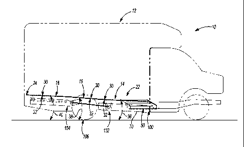
reference to the Figures 1-3, a bus 10 is illustrated to include a passenger
portion 12 having a first panel portion 14, a second panel portion 16, and a
third
panel portion 18 all of which cooperatively create an incline from a forward
area
22 of the bus 10 to a rearward area 24 of the bus 10.
For creating the incline, the one or more panel portions of the floor are
disposed at angles. The angles are taken for a bus with all wheels (fully
inflated)
disposed upon on a flat surface and the angles are relative to that flat
surface.
Moreover, the angles are taken for either a top surface, bottom surface or
both of
7
CA 02701127 2010-03-29
WO 2009/046065
PCT/US2008/078393
the panel portions relative to the flat surface. In the embodiment shown, the
first
panel portion 14, and particularly a top surface 30, a bottom surface 32 or
both
of the first panel portion 14 is typically at an angle 36 of at least about
0.8 ,
more typically at least about 1 , and even more typically at least about 1.5
or
1.8 relative to a flat surface upon which the bus is disposed. Also, the
angle 36
is typically less than 5 , more typically less than 3 , and even more
typically less
than 2.5 or 2.2 relative to the flat surface upon which the bus is disposed.
In
the embodiment shown, the second panel portion 16, and particularly a top
surface 30, a bottom surface 32 or both of the second panel portion 16 is at
an
angle 38 of at least about 1.5 , more typically at least about 2.5 , and even
more
typically at least about 3.5 or 3.8 relative to the flat surface upon which
the bus
is disposed. Also, the angle 38 is typically less than about 7 , more
typically less
than about 5.5 , and even more typically less than about 4.5 or 4.2 relative
to
the flat surface upon which the bus is disposed. In the embodiment shown, the
third panel portion 18, and particularly a top surface 30, a bottom surface 32
or
both of the third panel portion 18 is at an angle 40 of at least about 0.8 ,
more
typically at least about 1 , and even more typically at least about 1.5 or
1.8
relative to a flat surface upon which the bus is disposed. Also, the angle 40
is
typically less than 5 , more typically less than 3 , and even more typically
less
than 2.5 or 2.2 relative to the flat surface upon which the bus is disposed.
The angles of the portions of the bus preferably create an incline such
that the floor (i.e., the top or bottom surface) of the bus at the forward
area of the
bus is lower than the floor of the bus at the rearward area of the bus
relative to
the flat surface upon which the bus is disposed. Typically, the floor at the
forward area 22 of the bus is less than about 95%, more typically less than
90%
and even possibly less than about 85%, 80%, or 75% as high as the floor of the
rearward area 24 of the bus. It is also typical for the distance between the
forward area 22 of the bus and the rearward area 24 of the bus to be at least
about 10 feet (300cm), more typically at least about 13 feet (400cm), and even
possibly at least about 15 to 17 feet (460cm to 520cm). The distance between
the forward area and the rearward area is typically less than about 25 feet
8
CA 02701127 2010-03-29
WO 2009/046065
PCT/US2008/078393
(760cm), more typically less than about 21 feet (640cm) and even possibly less
than about 19 or 17 feet (580 or 520cm).
Any one, two or three of the first panel portion, the second panel and/or
the third panel portion each are angled along and/or extend along a percentage
of the distance between the forward and rearward portion. That percentage is
typically at least about 10%, more typically at least about 20% and even
possibly
at least about 30% of the distance. That percentage is typically less than
about
50%, more typically less than about 40% and even possibly less than about 35%
of the distance.
Although illustrated with three panel portions, it will be understood that the
floor may be divide into fewer portions or more portions with the given angles
to
create the incline.
Entrance Angle
An additional feature of the bus of the present invention is to have the
door disposed at an angle relative to the fore-aft axis of the bus. As can be
seen
in the Figure 5, a fore-aft axis (A) extends along a length (L) of the bus.
The
passenger entranceway 50 to the bus 10 includes a frame 52. Such frame 52
typically defines an opening into which the bus door 54 is fit. When the door
54
is in a closed position, it is typically substantially planar or lies
substantially within
a plane. In a preferred embodiment, the bus door 54, the plane in which the
door lies or both are disposed at an angle 64 relative to the fore-aft axis
(A) of
the bus 10. Preferably, the angle 64 lies in or opens is a plane that is
substantially or entirely perfectly horizontal, is substantially or entirely
perfectly
26
parallel to the flat surface upon which the wheels of the bus are disposed, is
substantially or entirely perpendicular to the plane in which the door lies or
any
combination thereof. The angle 64 is typically at least about 5 (although it
could
be 0 , particularly in the longer length vehicles), more typically at least
about 10 ,
and possibly at least about 150 or 20 . The angle 64 is also typically less
than
about 70 , more typically less than about 45 and even possibly less than
about
30 or 20 .
9
CA 02701127 2010-03-29
WO 2009/046065
PCT/US2008/078393
The overall length (L) of the bus (e.g., from front bumper periphery to rear
bumper periphery) is typically at least about 15 feet (450cm), more typically
at
least about 19 feet (580cm) and even possibly at least about 22 feet (670cm).
The length (L) is also typically less than about 40 feet (1220cm), more
typically
less than about 30 feet (915cm) and even possibly less than about 27 feet
(823cm). Length of these vehicles may also be typically defined in terms wheel
base (e.g. distance between the centers of the front and rear axles). The
typical
wheel bases for these vehicles may be greater than about 135 inches (345 cm)
and less than about 260 inches (660 cm), although the present invention
contemplates even wheel bases of greater length.
It is also contemplated that the passenger entranceway 50 of the bus 10
can include a ramp assembly 126 such that a ramp can be extended outwardly
from the passenger entranceway 50 of the bus 10. Such a ramp assembly 126
may be manual, automatic, or a combination thereof and may be powered by a
hydraulic system, and electrical system or a combination thereof.
As an additional or alternative feature, a lowest portion 70 of the
passenger entranceway 50 is relatively close to the flat surface upon which
the
wheels of the bus are disposed when the bus is disposed on such a flat
surface.
Typically, the lowest portion 70 is less than about 25 inches (63.5cm), more
typically less than about 18 inches (45cm) and even possible less than about
16,
13, or 11 inches (40, 33 or 28cm) from the surface. Typically the lowest
portion
70 is greater than 4 inches (10cm), more typically greater than about 8 inches
(20cm) and even possibly greater than 9 or 10 inches (22 or 25cm) from the
surface. These distances can be accomplished by virtue of the various features
described herein. Moreover, it may be the case that such distances are
accomplished using a movable suspension lift system as described below.
As an additional or alternative aspect, the bus can have a desired number
of dedicated seats, seating locations or a combination thereof. As used
herein, a
dedicated seat is a seat designed for one adult individual and a seating
location
is a seat or location on the bus designed for one handicapped person (e.g., an
individual in a wheelchair. It is contemplated that a bus according to the
present
CA 02701127 2015-01-30
4
invention can have dedicated seats, seating locations or a combination thereof
sufficient for at least ten individuals, at least fourteen individuals, at
least
eighteen individual or at least twenty-two individuals. The bus can also have
dedicated seats, seating locations or a combination thereof sufficient for
less
than forty individual, less than thirty individuals, less than twenty-five
individual or
less than twenty individuals. Of course, the bus can have higher or lower
number of dedicated seats or seating locations, unless otherwise specified.
Transmission System
As an additional or alternative aspect, the bus can have a transmission
system that essentially transmits the rotary drive motion from the engine to
the
rear axle via a drive shaft In a preferred embodiment, this transmission
system
is essentially direct (e.g. via a unitary multi-piece shaft), but in some
instances
the use of a drop-box system (e.g. a system to vertically drop the drive
motion
via gearing or chains) to lower the drive shaft is contemplated. An exemplary
drop-box system can be found in US Patent No. 6,702,057.
It is also contemplated that at an output point of the transmission to the
drive shaft should be at a height of no greater than about 18 inches (45mm)
above a support plane of the wheels (e.g. the centerline of the wheels) when
being driven or at about 14 inches (35mm) when the vehicle is kneeled or in
the
lowered position.
In another preferred aspect of the present invention, relevant to the drive
engine and transmission vertical position, an independent front suspension
like a
short-long-arm ("SLA") which permits a lower engine position in the chassis
may
be used. Other systems, such as a solid front axle or twin beam system,
common in Ford vehicles of this class and type, are contemplated, although
this
may force the engine up several inches and may preclude a direct connection of
the drive shaft to the transmission without the use of a drop box or transfer
case.
Additionally, as the buses get larger, with longer wheelbases, the bus could
be
11
CA 02701127 2015-01-30
4
built on a medium duty chassis with a solid beam front axle and a drop box to
lower the drive line.
In another preferred aspect of the present invention, relevant to the drive
engine and transmission vertical position, a solid rear axle may be utilized.
Other
known systems, such as multi-piece rear axles with a differential, are
contemplated to allow for a lower vertical position of the drive shaft. One
such
system is taught in US Patent No. 6,039,351.
Movable Suspension Lift System
As an additional or alternative aspect, the bus can have a suspension
system connected to the body structure and the frame assembly adapted to
raise and lower at least the entrance of the vehicle, but preferably to raise
and
lower the body structure, the drive motor and the drive transmission
vertically
relative to the flat surface upon which the wheels of the mass transit vehicle
are
disposed. At least in one embodiment, the movable suspension lift system
moves the lowest portion of the entranceway to the previously discussed
desired
distances from a flat surface upon which the vehicle is disposed. It is
contemplated that this movable suspension can be accomplished in any number
of ways known to one skilled in the art (e.g. direct pneumatic lift cylinders,
direct
hydraulic lift cylinders, two-bar lift systems, four-bar lift systems, airbag
lifts, or
the like). In a preferred embodiment, the suspension may include an airbag
lift
mechanism 124, as exemplarily shown in Fig. 7 in the raised position and in
Fig.
6 in the lowered or kneeling position, that is pneumatically actuated to lower
the
vehicle from a maximum position (e.g. driving position with maximum ground
clearance to the frame) to a minimum position (e.g. passenger loading position
with minimum ground clearance to the frame). Preferably the movable range of
the suspension system is at least about 2 inches (5cm), more preferably at
least
about 3 inches (7.5cm) and most preferably at least about 4 inches (10cm) or
more.
12
CA 02701127 2010-03-29
WO 2009/046065
PCT/US2008/078393
Solid Rear Axle Example
In an exemplary illustration, shown in Figs. 8-9, a range of values (+/-
10%) may be calculated for a number of vehicle packaging variables that may be
of interest so that the vehicle can meet the handicapped accessibility
requirements or other goals described for the present invention. These
variables
may include such as: the height of the floor of the vehicle at different fore-
aft
positions (e.g. rear axle region and near the driver/passenger portion
interface
region), the length and/or angles of panel portions, door height when vehicle
is in
a lowered position, and vehicle drive and/or transmission components. These
variables may be solved by using the following formulas:
MFHBC=ETH+ [VW/2 + DSO]*TAN (SR)
DSCLG=MFHBC ¨ KCLDS40DIS/S]
LIR=WB-FWCLBC-LZ
MFHRAB=MFHBC+LIR*TAN (191) +LZ*TAN (02)
MFHRAc=SLR+ [0DIFF/2] +KCLRA+FT
MFHRAB MFHRAc
Wherein the terms are defined as follows:
WB = Vehicle Wheelbase
VW = Vehicle Width
SLR = Tire Static Load Radius
ODIFF = Diameter of Rear Axle Differential Bowl
ODIS/S = Diameter of Driveshaft
ETH = Body entrance Threshold Height, Vehicle in lowered position ¨
"Kneeled" (lowest portion of the passenger entranceway)
OSR = Stowed ramp angle
FWCLBC = Front Wheel Centerline to Back of Driver Portion
LAR = Length of Rear Axle Region (Floor Panel Portion)
LIR = WB ¨ FWCLBC ¨ LZ
FT = Floor Thickness
KCLDS = Kneeled Clearance, Floor to Drive Shaft
KCLRA = Kneeled Clearance, Floor to Rear Axel Housing
13
CA 02701127 2010-03-29
WO 2009/046065
PCT/US2008/078393
091 = Side View Angle of Intermediate Region Floor (Floor Panel Portion)
e2 = Side View Angle of Rear Axle Region Floor (Floor Panel Portion)
MFHBC = Minimum Floor Height at Back of Driver Portion, Kneeled
MFHRA = Minimum Floor Height at Rear Axle Centerline, Kneeled
DSO ¨ Drive Shaft Offset from Vehicle Centerline
DSCLG = Drive Shaft Centerline to Ground, Kneeled
MFHRAB = Minimum Floor Height based upon a set floor height, Rear
Axle Region
MFHRAc = Minimum Floor Height based upon a set chassis height, Rear
Axle Region
U.S. Handicap Accessibility Requirements
The features discussed herein, alone or in any combination, can assist a
vehicle in abiding by one or any combination of the regulations discussed
below.
Of particular significance for such assistance is at least one or any
combination
of: the movable suspension lift system (e.g. level-change mechanism), the
floor
angles, door fame height and the ramp system (e.g. boarding device) disclosed
herein that enables the present invention to meet and/or exceed at least part
of
the below requirements (which are excepts taken from 36 CFR Part 1192 as
amended through September 1998):
Subpart B-Buses, Vans and Systems
1192.21 General.
(a) New, used or remanufactured buses and vans (except over-the-road
buses covered by subpart G of this part), to be considered accessible by
regulations issued by the Department of Transportation in 49 CFR part 37,
shall
comply with the applicable provisions of this subpart.
(b) If portions of the vehicle are modified in a way that affects or could
affect accessibility, each such portion shall comply, to the extent
practicable, with
the applicable provisions of this subpart. This provision does not require
that
inaccessible buses be retrofitted with lifts, ramps or other boarding devices.
1192.23 Mobility aid accessibility.
14
CA 02701127 2010-03-29
WO 2009/046065
PCT/US2008/078393
(a) General. All vehicles covered by this subpart shall provide a level-
change mechanism or boarding device (e.g., lift or ramp) complying with
paragraph (b) or (c); of this section and sufficient clearances to permit a
wheelchair or other mobility aid user to reach a securement location. At least
two
securement locations and devices, complying with paragraph (d) of this
section,
shall be provided on vehicles in excess of 22 feet in length; at least one
securement location and device, complying with paragraph (d) of this section,
shall be provided on vehicles 22 feet in length or less.
(5) Slope. Ramps shall have the least slope practicable and shall not
exceed 1:4 when deployed to ground level. If the height of the vehicle floor
from
which the ramp is deployed is 3 inches or less above a 6-inch curb, a maximum
slope of 1:4 is permitted; if the height of the vehicle floor from which the
ramp is
deployed is 6 inches or less, but greater than 3 inches, above a 6-inch curb,
a
maximum slope of 1:6 is permitted; if the height of the vehicle floor from
which
the ramp is deployed is 9 inches or less, but greater than 6 inches, above a 6-
inch curb, a maximum slope of 1:8 is permitted; if the height of the vehicle
floor
from which the ramp is deployed is greater than 9 inches above a 6-inch curb,
a
slope of 1:12 shall be achieved. Folding or telescoping ramps are permitted
provided they meet all structural requirements of this section.
1192.25 Doors, steps and thresholds.
(c) Door height. For vehicles in excess of 22 feet in length, the overhead
clearance between the top of the door opening and the raised lift platform, or
highest point of a ramp, shall be a minimum of 68 inches. For vehicles of 22
feet
in length or less, the overhead clearance between the top of the door opening
and the raised lift platform, or highest point of a ramp, shall be a minimum
of 56
inches.
It is to be understood that the features of the present invention can assist
a vehicle in abiding by these regulations; however, a vehicle need not abide
by
these regulations unless otherwise specifically stated.
Unless stated otherwise, dimensions and geometries of the various
structures depicted herein are not intended to be restrictive of the
invention, and
CA 02701127 2015-01-30
other dimensions or geometries are possible. Plural structural components can
be provided by a single integrated structure. Alternatively, a single
integrated
structure might be divided into separate plural components. In addition, while
a
feature of the present invention may have been described in the context of
only
one of the illustrated embodiments, such feature may be combined with one or
more other features of other embodiments, for any given application. It will
also
be appreciated from the above that the fabrication of the unique structures
herein and the operation thereof also constitute methods in accordance with
the
present invention.
The preferred embodiment of the present invention has been disclosed.
A person of ordinary skill in the art would realize however, that certain
modifications would come within the teachings of this invention. Therefore,
the
following claims should be studied to determine the true scope and content of
the invention.
The following discussion applies to the teachings as a whole. Unless
otherwise stated, all ranges include both endpoints and all numbers between
the
endpoints. The use of "about" or "approximately" in connection with a range
applies to both ends of the range. Thus, "about 20 to 30" is intended to cover
"about 20 to about 30", inclusive of at least the specified endpoints.
References to the term "consisting essentially of' to describe a combination
shall
include the elements, ingredients, components or steps identified, and such
other elements ingredients, components or steps that do not materially affect
the
basic and novel characteristics of the combination. The use of the terms
"comprising" or "including" to describe combinations of elements, ingredients,
c,omponents or steps herein also contemplates embodiments that consist
essentially of the elements, ingredients, components or steps.
Plural elements, ingredients, components or steps can be provided by a
single integrated element, ingredient, component or step. Alternatively, a
single
integrated element, ingredient, component or step might be divided into
separate
16
CA 02701127 2015-01-30
plural elements, ingredients, components or steps. The disclosure of "a" or
"one"
to describe an element, ingredient, component or step is not intended to
foreclose additional elements, ingredients, components or steps. Likewise, any
reference to "first" or "second" items is not intended to foreclose additional
items
(e.g., third, fourth, or more items); such additional items are also
contemplated,
unless otherwise stated.
It is understood that the above description is intended to be
illustrative and not restrictive. Many embodiments as well as many
applications
besides the examples provided will be apparent to those of skill in the art
upon
reading the above description. It is further intended that any combination of
the
features of different aspects or embodiments of the invention may be combined.
The scope of the invention should, therefore, be determined not with reference
to
the above description, but should instead be determined with reference to the
appended claims, along with the full scope of equivalents to which such claims
are entitled.
The omission in the following claims of any aspect of subject matter that is
disclosed herein is not a disclaimer of such subject matter, nor should it be
regarded that the inventors did not consider such subject matter to be part of
the
disclosed inventive subject matter.
17