Note: Descriptions are shown in the official language in which they were submitted.
CA 02701413 2010-03-31
WO 2009/058224 PCT/US2008/012108
APPARATUS FOR MAKING SLINGS HAVING A COVER
FIELD OF THE INVENTION
The present invention relates generally to non-metal slings and, in
particular, to an
apparatus for manufacturing non-metal roundslings.
BACKGROUND OF THE INVENTION
The term "rigging" (sometimes referred to as industrial rigging or field
rigging) is the
branch of securing heavy loads in order to prepare the load to be lifted,
moved or transported.
Rigging usually refers to the ropes, wires, slings, and chains used to secure
the load and not
the cranes, boomlifts, air skates, forklifts, or other powered equipment that
provides the
actual force/energy to lift the object.
Wire rope slings made of a plurality of metal strands twisted together and
secured by
large metal sleeves or collars are common in the industry. Since wire rope
slings are made of
metal, they do not require any protection that may be afforded by a covering
material. During
the past thirty years, industrial metal slings have seen improvements in
flexibility and
strength. However, compared to non-metal or synthetic fiber slings, metal
slings are
relatively stiff and inflexible.
Synthetic fiber slings have gained popularity over the last approximately
twenty years
and are replacing metal slings in many circumstances. Thousands of synthetic
slings are
being used on a daily basis in a broad variety of heavy load lifting
applications which range
from ordinary construction (e.g., nuclear power plants, skyscrapers and
bridges), plant and
CA 02701413 2010-03-31
WO 2009/058224 PCT/US2008/012108
2
equipment operations, to ship building (e.g., oil rigs), and the like.
An advantage of synthetic slings over metal slings is that they have a very
high load-
lifting performance strength-to-weight ratio which provides for a lighter,
more flexible and
even stronger slings than their heavier and bulkier metal counterparts. An
important
disadvantage is that synthetic slings require extra steps (primarily encasing
the lifting core
inside a protective cover), in its manufacturing process.
Synthetic slings are usually comprised of a lifting core made of twisted
strands of
synthetic fiber and an outer cover that protects the core. The most popular
design of synthetic
slings is a roundsling in which the lifting core forms a continuous loop and
the sling is
generally ring-shaped in appearance. The lifting core fibers of such
roundslings may be
derived from natural materials (e.g., cotton, linen, hemp, etc.), but are
preferably made of
hemp, linen, etc. synthetic materials, such as polyester, polyethylene, nylon,
and the like. The
outer covers of synthetic slings are preferably made of synthetic materials
and are designed to
protect the core fibers from abrasion, cutting by sharp edges, or degradation
from exposure to
heat, cold, ultraviolet rays, corrosive chemicals or gaseous materials, or
other environmental
pollutants.
A popular method of manufacturing of prior art roundslings is to twist a
plurality of
yarns together to form a single strand; the strand was then rolled into an
endless parallel loop
that formed the core. In a separate step, the cover would be manufactured as a
flat piece; then
the lifting core would be laid on the flat material, and the flat piece of
cover material would
be bent around the endless core; finally, the edges of the cover are sewn
together thereby
encasing the core. This method of manufacturing roundslings is time consuming
and labor
intensive thus increasing the costs to manufacture the sling.
CA 02701413 2010-03-31
WO 2009/058224 PCT/US2008/012108
3
An important advancement in the rigging industry was the invention of multiple-
path
slings by Dennis St. Germain. (See U.S. Patent No. 4,850,629, titled Multiple
Path Sling
Construction). The manufacturing process for a two-core roundsling is more
difficult since it
requires more time and labor than a single-core roundsling.
Machines used to manufacture round slings and multiple-path slings are still
relatively
labor intensive. Accordingly, there is a need in the industry to reduce the
amount of labor
needed in the manufacturing of synthetic slings.
SUMMARY OF THE INVENTION
It is a primary object of the present document to disclose an apparatus for
manufacturing non-metal slings and, in particular, an apparatus for making
multiple-path
slings.
The subject sling-making apparatus may take on a number of embodiments.
However, a preferred embodiment is the making of a two-path industrial sling,
i.e., a
roundsling having exactly two load-bearing cores.
The apparatus has three primary sections, namely, the yarn feeder assembly,
the
control assembly and the tail section assembly.
The yarn feeder assembly includes a yarn table consisting of a relatively flat
table-top
having a first end and a second end. The second end of the yarn table abuts
the control
assembly.
The control assembly includes an electric motor that provides the motive force
for the
sling-making apparatus, a power button used to turn the sling-making apparatus
on and off,
and a control circuit used to track the length of yarn used in the
manufacturing of the load-
CA 02701413 2010-03-31
WO 2009/058224 PCT/US2008/012108
4
bearing core.
The tail section assembly includes a pair of diametrically opposed rails on
which an
idler roller assembly rides. The pair of rails abut the side of the control
assembly opposite to
the side on which the yarn feeder assembly is located. The idler roller
assembly is comprised
primarily of an idler roller and the mating section for sliding on the rails.
The length of the
pair of rails depends on the maximum length of sling to which the sling-making
apparatus is
designed to make. In a preferred embodiment, the length of the rails is forty
feet and the idler
roller assembly can slide along the rails to make a roundsling up to eighty
feet in
circumference.
Once the length of the sling to be manufactured is determined, the idler
roller
assembly is slid, in a straight line, along the rails to the determined
position ¨ this is away
from the controller assembly for long slings and towards the controller
assembly for short
slings. The idler roller may be allowed to spin or it may be locked into
place.
As will be evident to one skilled in the art, and to provide maximum
adaptability for
its location, the sling-making apparatus may be left-handed or right-handed.
When the yarn
table is positioned to the left of the control assembly and the tail section
assembly is
positioned to the right of the control assembly, the sling-making apparatus is
considered left-
handed; when the yarn table is positioned to the right of the control assembly
and the tail
section assembly is positioned to the left of the control assembly, the sling-
making apparatus
is considered right-handed. However, the side on which each assembly is
located with
respect to the center control assembly does not affect the operation or
process of making a
sling.
CA 02701413 2010-03-31
WO 2009/058224 PCT/US2008/012108
BRIEF DESCRIPTION OF THE DRAWINGS
The accompanying drawings, which are incorporated in and form a part of the
specification, illustrate the embodiments of the present invention and,
together with the
following description, serve to explain the principles of the invention. For
the purpose of
illustrating the invention, there are shown in the drawings embodiments which
are presently
preferred, it being understood, however, that the invention is not limited to
the specific
instrumentality or the precise arrangement of elements or process steps
disclosed.
In the drawings:
Figure lA is a top plan view of an apparatus for making slings in accordance
with the
present invention;
Figure 1B is a side view of the apparatus illustrated in Figure 1A;
Figure 2A is a top plan view of the fiber guide/separator that forms a part of
the yarn
table assembly;
Figure 2B is a side view of the fiber guide/separator shown in Fig. 2A;
Figure 3A is a top plan view of the control assembly and tail section assembly
of the
subject apparatus;
Figure 3B is a side view of the control assembly and tail section assembly of
Figure
3A;
Figure 4A is a side view of the encoder wheel which forms a part of the
control; and
Figure 4B is a top view of the encoder wheel shown in Figure 4A.
DETAILED DESCRIPTION OF THE PREFERRED EMBODIMENT
In describing a preferred embodiment of the invention, specific terminology
will be
CA 02701413 2010-03-31
WO 2009/058224 PCT/US2008/012108
6
selected for the sake of clarity. However, the invention is not intended to be
limited to the
specific terms so selected, and it is to be understood that each specific term
includes all
technical equivalents that operate in a similar manner to accomplish a similar
purpose.
Before the invention is disclosed, it is important to remember some
terminology used
in the rigging industry and to understand the parts of a sling is made. The
term "roundsling"
is used to refer to a sling having a ring-like or circular shape. A roundsling
has two primary
sections; namely, a load-bearing core and a tubular cover which protects the
load-bearing
core. In a single core roundsling, there is one endless load-bearing core. In
a roundsling
having exactly two load-bearing cores (e.g., TWIN-PATH brand dual-core
slings), the
cover has two separate and distinct channels parallel to each other, and two
endless load-
bearing cores situated within its own respective channel in the cover.
Definitions:
Abrasion: The mechanical wearing of a surface resulting from frictional
contact with
materials or objects.
Breaking Strength: The total force (lb. or kg.) at which the sling fails. The
total
weight strain which can be applied before failure, which is usually at least
five times the rated
capacity.
Core: The load-bearing multiple fibers of synthetic material which when wound
into
the seamless tubes becomes the load-bearing yarns of the sling.
CA 02701413 2010-03-31
WO 2009/058224 PCT/US2008/012108
7
Cover: The seamless tubes that contains the cores. Covers may be of polyester,
covermax, Aramid, or other suitable material depending on the desired finished
characteristics of the product. Preferably, the cover is made of an inner
material hearing a
high visibility color, and an outer material made of a contrasting color; when
the outer cover
material is damaged or worn through, the inner cover material becomes visible
allowing for a
quick inspection means.
Elongation: The measurement of stretch, expressed as a percentage of the
finished
length.
Fitting: A load-bearing metal component which is fitted to the sling. A
fitting can be
made from steel, aluminum or other material that will sustain the rated
capacity of the sling.
The fitting must be smooth and large enough to allow the sling to perform
without bunching.
Length: The distance between bearing points of the sling when laid flat and
closed.
Measurements are taken from the inside points of contact.
Proof Test: A term designating a tensile test applied to the item for the sole
purpose of
detecting injurious defects in the material or manufacture.
Synthetic Fiber: Any of a multiple of man-made materials used to manufacture
the
cover, the core, and the thread of the non-metal slings.
CA 02701413 2013-11-25
8
Tell-Tails: Core yarns which extend past the tag area of each sling. When the
sling is
stretched beyond its elastic limit, they shrink and eventually disappear under
the tag. If either
tell-tail is showing less than 1/2", the sling must be removed from service.
If the tell-tails
show evidence of chemical degradation, the sling must be removed from service.
These may
be a fiber-optic cable which will help identify core deterioration.
Thread: The synthetic yarn which is used to sew the slings, covers, tag and
also to
provide the stitch which separates the individual load covers.
Multiple-path non-metal slings were unknown approximately twenty-five years
ago.
Dennis St. Germain, the inventor herein, invented multiple-path slings in the
mid-1980's.
The multiple-path sling and, in particular, a sling having exactly two load-
bearing cores, has
been a commercial success. Slings having two load-bearing cores are sold under
the TWIN-
PATH brand. The multiple-path sling is described in U.S. Pat. No. 4,850,629,
titled
MULTIPLE PATH SLING CONSTRUCTION.
Preferred embodiments of the present invention will now be described in detail
with
reference to the accompanying drawings in which an apparatus for making slings
in
accordance with the present invention is generally indicated at 10.
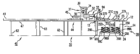
Referring now to Figures 1 A and 1B, a yarn feeder assembly 20, a control
assembly
30 and a tail section assembly 40 are shown. The yarn feeder assembly 20
includes a yarn
feeder table 22 having a flat table top 11 with a first end 12 and a second
end 13; the second
end is abutted up against and, is preferably attached to, the control assembly
30. As
CA 02701413 2013-11-25
9
illustrated in Figure 1B, the yarn feeder table 22 has one or more legs 14 to
support the table
top 11.
Spaced at regular intervals, the yarn feeder table 22 has a plurality of
openings 23 for
allowing an individual strand 25 of yarn to pass therethrough. The individual
strands of yarn
will be twisted together, as will be described herein, to make the load-
bearing inner core of the
sling. Figure lA illustrates an apparatus 10 having exactly eight yarns used
to make the inner
core; therefore, this particular yarn table has openings 23A through 2311. If
the machine is set
up to manufacture a multiple-path (e.g., a TWIN-PATH brand dual-core sling),
the yarns are
twisted together to make each core of the multiple-path sling.
The individual strands are made in a separate manufacturing step. As an
individual
strand of yarn is manufactured, it is rolled onto a heavy-weight cardboard
tube. Once the
desired length of yarn is rolled onto the heavy-weight cardboard tube, the
yarns are delivered
to customers in a spool or roll 99. The denier, weight and materials used to
manufacture the
yarn are chosen depending on the type and size of sling to be manufactured.
However, in
order to reduce inventory, to keep storage space at a minimum, and to
streamline the
manufacturing process, it is preferable to choose one medium-weight synthetic
yarn.
Beneath the yarn feeder table 22 lies a spool table 24 for holding a plurality
of spools
99 of yarn. In a preferred embodiment, as illustrated in Figure 1B, yarn table
22 can hold two
rows of four rolls of yarn (for a total of eight rolls), wherein yarn 25A is
unrolled from spool
99A, yarn 25B is unrolled from spool 99B, etc. However, not every sling that
will be
manufactured will use the maximum number of yarns. For example, slings
designed and rated
to lift relatively small loads may use less than eight yarns.
The spool table 24 has a plurality of elongated extensions 26A, 26B, 26C
through
CA 02701413 2010-03-31
WO 2009/058224 PCT/US2008/012108
26H (preferably rod-shaped) that extend from the top surface of the spool
table towards the
underside of the yarn table 22. (Although extensions 26E through 26H cannot be
seen from
the drawings, each half of the spool table is identical.) A spool of yam 99 is
slid vertically
over each of the extensions 26 on the spool table 24 and the spool's weight
keeps it on the
spool table.
The number of elongated extensions 26 are ultimately determined by the maximum
size of sling to be manufactured on the apparatus 10. The number of spools of
yam 99 used
to manufacture a specific sling depends on the size of the sling to be
manufactured at that
time. The number of spools of yam 99 should not exceed the number of elongated
extensions
on the spool table. Although the disclosure and the drawings illustrate that
there are eight
spools of yam that are slid over eight elongated extensions 26, the spool
table can be enlarged
to accommodate more elongated extensions 26 and more spools 99 in order to
make larger
slings. Similarly, apparatus 10 that are designed to make lower-strength
slings may not
require a yarn table that can accommodate eight yams.
The number of spools that can be held by the spool table 24 corresponds to the
number of openings 23A, through 23H in the yam table. Once the size of the
sling to be
manufactured is determined, the number of yams to be used to form the load-
bearing core can
be calculated based on the known weight an individual yam can hold. Although
the first time
a sling is made, the number of yams and other factors may be calculated, some
of this
information may be obtained through trial and error by manufacturing slings
made of varying
diameters of yam, destructively testing the sling, and recording the results.
Over time, the
number of yams needed to manufacture a specific load-bearing core will become
well-known
since all of the other measurements are known (e.g., the thickness of the yam
used, etc.) For
CA 02701413 2013-11-25
11
example, by doing an initial calculation, then through years of experience in
making slings, it
is known that eight yarns of relatively medium weight synthetic (e.g., Kevlar0
of Kev'art
blend) yarn are required to manufacture the load-bearing core of a 20,000
pound sling. This
information can be collected and quantified in a chart which can be consulted
by the operator
immediately before the manufacturing process.
Referring again to Figures lA and 1B, proximate each yarn opening 23A through
23H,
is a spring-tensioning device 27A through 27H, respectively. The spring-
tensioning devices
27A through 2711 applies proper resistance to its respective yarn to prevent
any slack in the
yarn during the cover-making step. The spring-tensioning devices each have
their own
adjustment to increase or decrease the amount of tension applied to its
respective yarn. The
spring-tensioning devices are well-known in the industry.
The sling-making apparatus 10 includes an encoder 29. The location of encoder
29 can
be seen in Figures 1A, 1B, 3A and 3B. The encoder 29 includes an encoder wheel
98 and its
related circuitry that counts the number of revolutions of the encoder wheel.
Referring now to Figures 4A and 4B, an enlarged view of the encoder wheel 98
is
shown. The encoder wheel 98 has a central groove 65 of known circumference.
The circuitry is
preferably stored in control box 34. One of the yarns (preferably one farthest
away from the
control assembly) is wrapped at least partially around the encoder wheel 98.
Since the wheel's
circumference is known, the length of the yarn used to manufacture the load-
bearing core will
be easy to compute. As one skilled in the art can appreciate, after reading
the present
disclosure, the encoder circuitry may be modified to provide a reading in any
length
measurement (e.g., feet, yards, meters, etc.)
A counter circuit that is connected to the wheel actually determines how many
feet are
CA 02701413 2013-11-25
12
used. Since the circumference of the wheel is known (2 * pi * r - where "r" is
the radius of the
wheel 98 in feet), the number of rotations of the wheel will convey the number
of feet of yarn
that has been pulled from a roll 99 to make the inner core(s). The encoder and
its associated
circuitry are well-known off-the-shelf products.
Referring again to FIGS. 1A and 1B, the location of a comb or fiber guide 92
proximate
the second end 13 of the yarn table 11 is shown. Preferably the fiber guide 92
is positioned at the
junction between the yarn table assembly 20 and the control assembly 30. The
fiber guide 92
ensures that the yarns do not prematurely begin twisting and/or become
tangled. The fiber guide
92 includes a base section 93 and a plurality of elongated projections 94
(sometimes referred to
as "teeth" or "tines"). The base section 93 has a plurality of projection-
holding receptacles 95
into which the elongated projections 94 may be inserted. The elongated
projections 94 are
preferably rod-shaped and are removable and can be re-inserted into different
holding recesses
to adjust the separation between each individual yarn with respect to adjacent
yarns.
An enlarged view of the base section 93 of the fiber guide 92 is illustrated
in FIGS. 2A
and 28. The base 93 may be made of wood or metal and is secured to the yarn
table by using
bolts 91. The base 93 preferably has more projection-holding receptacles 95
than there are the
elongated projections 94 (commonly referred to as "teeth"). Each projection 94
is inserted into a
desired receptacle 95 and secured preferably by a friction fit.
The receptacles 95 do not have to be spaced in a regular pattern but it may be
easier to
manufacture the base 93 if they are spaced apart in a regular or repeating
manner. The operator
of the machine 10 may insert one or more teeth 96 into the receptacles. The
primary factor for
determining the number of teeth 96 to be inserted into receptacles 95 is the
size of the sling to be
made which will determine the number of yarns that will be used to make the
core.
The fiber guide 92 is designed to keep the yarns separated until the last
possible second
CA 02701413 2013-11-25
13
to ensure a tight twisting of the yarns as it forms the load-bearing core of
the sling. In one
embodiment, the teeth 94 are shaped like rods and are frictionally-fitted into
the receptacles 95.
In another embodiment, one end of each projection 94 can be manufactured with
threads, and
the receptacles 95 can be manufactured with mating threads so that the
projection 94 may be
screwed into its respective receptacle. By moving the projection 94 into
different receptacles 95,
the separation of the yarns can be controlled and managed, and ultimately the
"tightness" of the
wrap of yarns that form the load-bearing core can be controlled.
Referring again to FIGS. 1A and 1B, the control assembly 30, including a
control box 34
housing control circuitry, and control panel 31 are illustrated. As stated
previously, the counter
circuit for the encoder 29 may also be stored in the control box 34. A display
35 that is
electrically connected to the counter circuit may be mounted on the control
panel 31 for
conveying to the machine's operator the length of yarn pulled from the spool
99 of yarn and used
to manufacture the load-bearing core.
The control assembly 30 also includes an electric motor 32 that provides the
motive
force for the apparatus 10. The electric motor 32 turns a drive roller 38 and
is connected by a
chain (using sprockets), belt or preferably a worm gear reducer 33. An on/off
switch 39
CA 02701413 2010-03-31
WO 2009/058224 PCT/US2008/012108
14
controls power to the apparatus 10 and, more specifically to the control
circuit.
The encoder 29 along with the encoder wheel 98 are illustrated as being
mounted on
the yarn table 11, but may be placed anywhere so that at least one yarn can
engage the wheel
98 to turn it, thereby allowing the encoder circuit to determine the length of
yarn used to
manufacture the load-bearing core. The encoder display 35 conveys to the
operator how
many feet of yarn was used in manufacturing the load-bearing core.
Referring now to Figures 3A and 3B, the control assembly is mounted on a table
61
supported by one or more legs 62. The tail section assembly 40 may be mounted
on a table or
an open frame 47 so that the working area of the yarn table assembly 20,
control assembly 30
and tail section assembly 40 are all relatively in the same working plane. One
or more legs
63 support the frame 47 of the tail assembly 40. The apparatus 10 is designed
to be
somewhat modular to allow for easy assembly and disassembly.
The tail-back assembly 40 is positioned after the control assembly 30. The
tail-back
assembly 40 includes a pair of rails 41, 42 on which an idler roller section
44 slides. The rails
ensure that the idler roller assembly 44, and in particular the idler roller
45, is parallel to the
drive roller. This, in turn, ensures that the yarns that form the load-bearing
core are properly
twisted and slide with the least amount of friction into the cover of the
sling.
The idler roller section 44 is slidably attached to the pair of rails 41, 42
for moving the
idler roller section in a straight line (i.e., horizontal motion) away from or
towards the motor-
driven roller 38. The straight-line distance between the idler roller 45 and
the driven roller 38
is approximately one-half the size of the sling that is being made. In other
words, if it is
desired to make a roundsling having a twenty-foot perimeter, the idler roller
section is
CA 02701413 2010-03-31
WO 2009/058224 PCT/US2008/012108
positioned ten feet away from the driven roller.
The idler roller section 44 includes means for locking down the idler roller
section to
One or both rails 41, 42 thereby preventing the idler roller section 44 from
sliding along the
rails during the manufacture of the sling. The locking means may be one or
more bolts that
are secured to the idler roller section 44 and which can be tightened so the
bolts frictionally
engage one or both rails. As the drive roller 38 pulls the yarn into the cover
of the roundsling,
a certain amount of tension is created on the idler roller section 44. By
locking the idler roller
section 44 into place, the load-bearing cores can be manufactured in
substantially one
continuous step.
In one embodiment, the operator keeps track of the number of feet as indicated
on the
encoder display 35 and stops the apparatus 10 using the on/off switch when the
requisite
length of yarn to form the load-bearing core is drawn from the spools 99 of
yarn. The actual
length of yarn pulled from the spools 99 and used to form the load-bearing
cores is not
precise as long as the minimum length that was calculated at the beginning of
the process is
used. A few extra feet will only strengthen the load-bearing cores.
In the preferred embodiment, an electronic decoder control circuit may be
employed
to automatically turn off the apparatus when the minimum length of yarn is
pulled from the
spool. As in the manual process, the encoder wheel 29 is used to determine the
length of yarn
pulled from the spool during the manufacturing of the load-bearing core. The
counter circuit
can be integrated into the control circuitry via the electronic decoder
control circuit for
turning off the power to the electric motor when a pre-determined number of
feet is pulled
from the spool. The operator will program the number of feet of yarn to be
used to
manufacture the load-bearing cores into the control circuitry at the beginning
of the
CA 02701413 2010-03-31
WO 2009/058224 PCT/US2008/012108
16
manufacturing process. After the operator turns on the machine 10, the motor
will continue
to run until the number of feet programmed into the control circuitry is
reached as determined
by the encoder wheel 29 and signaled to the control circuitry. In this manner,
the control
circuitry will automatically turn the machine off thereby stopping the motor
and the drive
roller. Automating this step in the manufacturing process frees the operator
to monitor other
steps.
As indicated previously, the encoder and its associated circuitry are off-the-
shelf items
that can be easily incorporated in the power circuit of the present machine
10.
During the manufacturing process, the cover of the sling is placed around the
idler
roller 45. As indicated previously, a leader yarn has been threaded through
the channel of the
sling cover. In a sling having two load-bearing cores, the cover has two
channels in parallel
relationship; in this embodiment, a leader yarn is threaded through both
channels in the cover.
Similarly, for slings having more than two load-bearing cores, a leader yarn
is thread through
each channel of the cover.
The cover of the sling is cut to allow access to the interior of the cover.
The exposed
leader yarn has its ends tied together to form an endless loop. The leader
yarn is then placed
around the drive roller 38. The idler roller section 44 is then slid away from
the control
assembly thereby placing tension on the leader yarn. The number of yarns
(e.g., eight) that
were determined to be needed to form each load-bearing core are then tied to
each leader
yarn.
When the machine 10 is turned on, the leader yarns, being in frictional
contact with
the driver roller 38, begins to rotate within their respective cover channels.
As the leader
yarns rotate, they pull a plurality of yarns off of the spools. As the yams
are pulled from their
CA 02701413 2010-03-31
WO 2009/058224
PCT/US2008/012108
17
spools, then through comb 92, and they are drawn eventually through their
respective
channels in the cover in a circular motion. The plurality of individual yarns
begin to twist in
a regular manner as they are drawn within the channel of the cover thereby
forming the
endless-loop load-bearing cores.
A preferred embodiment is the making of a two-path industrial sling. The
process of
making a two-path sling using the apparatus that is the subject of this patent
application is
straight forward once the apparatus has been disclosed.
In order to streamline the manufacturing process, the covers are manufactured
in an
independent step. In this manner, hundreds or thousands of covers can be
manufactured at a
time. Moreover, the covers can be manufactured off-site using conventional
manufacturing
techniques. The covers are then shipped to the location where the subject
sling-making
apparatus is located to manufacture the load-bearing core and for final
assembly of the sling.
The covers are manufactured with a leader line in each channel. Therefore, if
a two-core
roundsling is to be made, the cover is manufactured having two channels and
there are two
leader lines placed in the cover-one for each channel.
The first step in the manufacturing of a sling is to determine the size of
sling to be
made (including diameter of load-bearing core which depends on the weight to
be lifted and
the overall length of the sling) and to determine the type of sling to be
made. Based on the
size (in particular the length), the idler roller assembly 44 is slid along
the rails 41, 42 to the
proper position and secured by the lock-down means.
The next step in manufacturing a sling involves selecting the appropriate
cover
material as determined by the sling type and/or customer specifications.
Generally, the
required length of tubing to form the cover is twice the desired length plus
five feet.
CA 02701413 2010-03-31
WO 2009/058224 PCT/US2008/012108
18
In a preferred embodiment, the inner-side of the cover material will be a
contrasting
color than the outer-side of the cover material to expedite the inspection
process.
All multiple-core slings are fabricated using the same basic instructions. The
required
tube widths and requirements are determined by trial-and-error or through
experience, and
may be quantified and placed in a chart for future look-up.
Next, the operator moves the (non-rotating) tail stock to the appropriate
position as
determined by the sling length (2 x sling length + about five feet) and
secures the tail stock
using securing clamps or other means provided to secure the tail stock.
Using a vise grip pliers or other suitable tool, the operator clamps the end
of the cover
with the long rolled back cuff to the cross bar 83. The operator then pulls
the cover towards
the tail stock assembly 40 and loops the cover material around the idler
roller 45.
The next step in the manufacturing process is to tie the required number of
yarns to
the leader yarn in the cover. Any excess polyester leader yarn is cut off
after tying it to the
cover yarns 99. The core yarn is inserted into this original loop, and secured
(e.g., by taping)
in place allowing a sufficient tail. This tail will be used to tie the
beginning yarn to the end
yarn after load-bearing core is made.
Once the yarns 99 are tied to the leader yarn, the operator hits the on/off
switch 39 to
start the electric motor 32 thereby turning the drive roller. The sling-making
machine 10 is
run until the requisite number of loops, or more accurately the requisite
length of yarn 99 has
been pulled from the spools. The minimum number of feet of yarn that was
calculated at the
beginning of the manufacturing process must be pulled from the spools for the
size and load-
bearing capacity of the sling to be made. (The number of loops of the load-
bearing core that
are formed depends on the distance between the idler roller and the drive
roller.) The motor
CA 02701413 2010-03-31
WO 2009/058224 PCT/US2008/012108
19
is pulsed on and off until the original loops and tails are positioned at the
drive roller and are
accessible to the operator. Since the cover does not rotate during the
manufacturing process,
the opening of the cover remains proximate to the driver roller.
The operator feeds each of the filler strands through its respective hole in
yarn table
and through the tension wheels. The operator adjusts the tension wheels to
ensure that there
is sufficient tension as the drive roller pulls the yarn from its respective
spool.
Although any of the yarns may be used to wrap around the encoder wheel 98, the
yarn
from the spool furthest from the drive roller is preferred.
The operator loops the filler yarns through the bowline knot of each leader
string
allowing a sufficiently long tail and then tapes them into an interlocking
loop.
The operator then places pins in the fiber guide 92 to separate the strands
entering the
cover paths.
In order to ensure that an appropriate amount of tension is applied to the
leader
strings, the idler roller 45 may have to be readjusted. The leader strings
must be snug against
the drive roller 38 so that when the drive roller rotates, the leader string
is pulled through its
respective channel in the cover. For a multiple-path sling, each leader
strings requires
substantially equal tension.
The operator ties a (bowline) knot on each leader string at the end of the
cuff. While
holding the top knotted end of the leader string, the operator loops the
bottom end around the
drive roller. The operator pulls out any excess slack from each leader string.
The operator
then pulls the unlcnotted end until the desired tension is achieved and
secures the unknotted
end with two half hitches. The operator then cuts off any excess leader
string. These steps
CA 02701413 2013-11-25
are repeated for each of the remaining leader strings if all paths are to be
run at the same time.
The operator then turns on the machine 10 by switching the switch 39 from off
to on, and
carefully feeds the yam into the channels of the covers.
When the counter indicates that the appropriate amount of core material has
been used to
form the load-bearing cores, the control circuitry from the encoder 29 will
automatically stop the
machine. As a check, the operator may count the number of strands needed to
form each of the
load-bearing cores.
The ends of the load-bearing core are tied together. The sling can then be
removed from
the drive roller 38 and idler roller 44. It should be noted that some slings
are best manufactured
locking the idler roller 44 to prevent rotation.
The cover is sewn over the opening and closed up allowing only the tell-tails
to be seen
outside the cover, thereby completing the sling.
Although this invention has been described and illustrated by reference to
specific
embodiments, it will be apparent to those skilled in the art that various
changes, modifications
and equivalents may be made which clearly fall within the scope of this
invention.