Language selection

Search

Patent 2702597 Summary

Third-party information liability

Some of the information on this Web page has been provided by external sources. The Government of Canada is not responsible for the accuracy, reliability or currency of the information supplied by external sources. Users wishing to rely upon this information should consult directly with the source of the information. Content provided by external sources is not subject to official languages, privacy and accessibility requirements.

Claims and Abstract availability

Any discrepancies in the text and image of the Claims and Abstract are due to differing posting times. Text of the Claims and Abstract are posted:

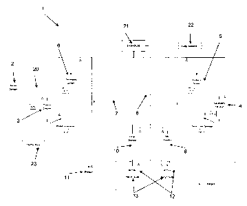
  • At the time the application is open to public inspection;
  • At the time of issue of the patent (grant).
(12) Patent Application: (11) CA 2702597
(54) English Title: CRUSHING AND BLENDING SYSTEM AND METHOD
(54) French Title: SYSTEME ET PROCEDE DE BROYAGE ET DE MELANGE
Status: Deemed Abandoned and Beyond the Period of Reinstatement - Pending Response to Notice of Disregarded Communication
Bibliographic Data
(51) International Patent Classification (IPC):
  • B02C 23/12 (2006.01)
  • B02C 23/14 (2006.01)
(72) Inventors :
  • CARRIERE, PAT (Canada)
  • MIDDLEDITCH, DAVE (Canada)
  • FRAGOMENI, DOMINIC (Canada)
(73) Owners :
  • XSTRATA CANADA CORPORATION
(71) Applicants :
  • XSTRATA CANADA CORPORATION (Canada)
(74) Agent: LAVERY, DE BILLY, LLP
(74) Associate agent:
(45) Issued:
(22) Filed Date: 2010-05-04
(41) Open to Public Inspection: 2011-11-04
Availability of licence: N/A
Dedicated to the Public: N/A
(25) Language of filing: English

Patent Cooperation Treaty (PCT): No

(30) Application Priority Data: None

Abstracts

English Abstract


A crushing apparatus for crushing a material including a first crusher for
crushing the
material into a first output; a first conveyor for transporting the first
output; a first screen for
separating the first output conveyed by the first conveyor into a first
screened material and a
second screened material; a second crusher for crushing the second screened
material into
a second output; a second conveyor for transporting the second output and the
first
screened material that are respectively received from the second crusher and
the first
screen; and a second screen for separating the second output and the first
screen material
conveyed by the second conveyor into a product material and a third screened
material;
wherein the third screened material is received by the first conveyor.


Claims

Note: Claims are shown in the official language in which they were submitted.

CLAIMS:
1. A crushing apparatus for crushing a material comprising:
a first crusher for crushing the material into a first output;
a first conveyor for transporting the first output;
a first screen for separating the first output conveyed by the first conveyor
into a first
screened material and a second screened material;
a second crusher for crushing the second screened material into a second
output;
a second conveyor for transporting the second output and the first screened
material
that are respectively received from the second crusher and the first screen;
and
a second screen for separating the second output and the first screen material
conveyed by the second conveyor into a product material and a third screened
material;
wherein the third screened material is received by the first conveyor.
2. A method for crushing a material comprising:
crushing the material with a first crusher into a first output;
conveying the first output of the first crusher to a first screen;
separating the first output at the first screen into a first screened material
and a second
screened material;
crushing the second screened material with a second crusher into a second
output;
conveying the second output and the first screened material towards a second
screen;
separating the second output and the first screened material at the second
screen into
a product material and a third screened material; and
conveying the third screened material towards the first screen.
3. A mixing apparatus for mixing a material comprising:
a mixer for mixing the material into a mixed output; and
a riffler for riffling the mixed output into a riffled output.
4. A method for mixing a material comprising:
mixing the material in a mixer into a mixed output;
riffling the mixed output with a riffler into riffled output.

6
5. A crushing and mixing apparatus comprising:
a first crusher for crushing the material into a first output;
a first conveyor for transporting the first output;
a first screen for separating the first output conveyed by the first conveyor
into a first
screened material and a second screened material;
a second crusher for crushing the second screened material into a second
output;
a second conveyor for transporting the second output and the first screened
material
that are respectively received from the second crusher and the first screen;
and
a second screen for separating the second output and the first screen material
conveyed by the second conveyor into a product material and a third screened
material;
a mixer for mixing the product material into a mixed output; and
a riffler for riffling the mixed output into a riffled output;
wherein the third screened material is received by the first conveyor.
6. The crushing apparatus according to claim 1, wherein the conveyors are
variable speed.
7. The crushing apparatus according to claim 1, wherein the first crusher is a
jaw crusher.
8. The crushing apparatus according to claim 1, wherein the second crusher is
a jaw
crusher.
9. The crushing apparatus according to claim 1, wherein the first screen is a
double deck
vibrating screen.
10. The crushing apparatus according to claim 1, wherein the second screen is
a single
deck vibrating screen.
11. The crushing apparatus according to claim 1, wherein the product material
is crushed to
a relative standard deviation of less than 5%.
12. The crushing method according to claim 2, wherein the conveyors are
variable speed.
13. The crushing method according to claim 2, wherein the first crusher is a
jaw crusher.

7
14. The crushing method according to claim 2, wherein the second crusher is a
jaw crusher.
15. The crushing method according to claim 2, wherein the first screen is a
double deck
vibrating screen.
16. The crushing method according to claim 2, wherein the second screen is a
single deck
vibrating screen.
17. The crushing method according to claim 2, wherein the product material is
crushed to a
relative standard deviation of less than 5%.
18. The crushing and mixing apparatus according to claim 5, further comprising
a second
mixer for mixing the product material into a second mixed output and at second
riffler for
riffling the second mixed output into a second riffled output.
19. A mixing apparatus according to claim 3, wherein the riffler is spinning
riffler.
20. The crushing and mixing apparatus according to claim 5, wherein the
riffler is a spinning
riffler.

Description

Note: Descriptions are shown in the official language in which they were submitted.


CA 02702597 2010-05-04
1
CRUSHING AND BLENDING SYSTEM AND METHOD
FIELD OF THE INVENTION
[0001] The present invention relates to a crushing and blending system and
method.
More specifically, the present invention is concerned with a crushing and
blending plant and
method which allows for the efficient and cost effective crushing and blending
of drill core or
rock for lab sampling ahead of a bench scale floatation or pilot plant
testwork.
BACKGROUND OF THE INVENTION
[0002] In the mining industry, the preparation of drill core or rock (top size
6 inch)
through crushing and blending is an important first step ahead of bench scale
flotation or
pilot plant testwork.
[0003] There is known in the prior art systems and methods which employ
various
connected stages for crushing and mixing for the processing of rock materials.
However,
such know prior art system and methods are somewhat inefficient and costly.
There is
therefore a need for a more efficient system and methods for crushing and
blending of rock
or drill core in preparation for use ahead of a bench scale floatation or
pilot plant testwork.
SUMMARY OF THE INVENTION
[0004] More specifically, in accordance with the present invention, there is
provided
an efficient crushing and blending system that produces high quality blended
material by
reiteratively crushing and then mixing rock or drill core for preparation for
use ahead of a
bench scale floatation or pilot plant testwork.
[0005] In embodiments, the crushing and blending system according to the
present
invention produces blended material with a level of relative standard
deviation (RSD) of less
than five percent (5%) and which does so in a fraction of the time compared to
that of
manual methods.

CA 02702597 2010-05-04
2
BRIEF DESCRIPTION OF THE DRAWINGS
[0006] In the appended drawings:
[0007] Figure 1 is a schematic flow sheet of a crushing and blending plant,
according
to a preferred embodiment of the present invention;
[0008] Figure 2 is a front isometric view of the crushing and blending plant,
according
to a preferred embodiment of the present invention;
[0009] Figure 3 is a rear isometric view of a crushing and blending plant
shown in
Figure 2;
[0010] Figure 4 is a rear elevation view of a crushing and blending plant
shown in
Figure 2;
[0011] Figure 5 is a front elevation view of a crushing and blending plant
shown in
Figure 2;
[0012] Figure 6 is a top plan view of a crushing and blending plant shown in
Figure 2;
[0013] Figure 7 is a side view of a primary crusher platform forming part of
the
crushing and blending plant shown in Figure 2;
[0014] Figure 8 is a side view of the crusher platform shown in Figure 7;
[0015] Figure 9 is a front view of a blending station, according to a
preferred
embodiment of the present invention;
[0016] Figure 10 is a top view of the blending station shown in Figure 9;
[0017] Figure 11 is an isometric view of the blending station shown in Figure
9;
[0018] Figure 12 is a isometric view of a secondary crusher, according to a
preferred
embodiment of the present invention;
[0019] Figure 13A is side view of a screen, according to a preferred
embodiment of
the present invention;

CA 02702597 2010-05-04
3
[0020] Figure 13B is section view taken at line A-A of the screen shown in
Figure
13A;
[0021] Figures 14A and 14B are respectively side and top views of a small
blender,
according to a preferred embodiment of the present invention;
[0022] Figures 15A and 15B are respectively side and top views of a small
blender,
according to a preferred embodiment of the present invention;
[0023] Figure 16 is an isometric view of a flexible feed mechanism with a
barrel drum,
according to a preferred embodiment of the present invention; and
[0024] Figure 17 is an isometric view of a flexible feed mechanism adapted to
receive
a pail, according to a preferred embodiment of the present invention.
DESCRIPTION OF ILLUSTRATIVE EMBODIMENTS
[0025] The present invention is illustrated in further detail by the following
non-limiting
example.
[0026] Figure 1 is a schematic of a crushing and blending plant flow sheet.
The
crushing and blending plant I consists of a high level drum dumper 2, an eight
by ten feet
DenverTM primary jaw crusher 3, a secondary RocklabTM small Boyd TM jaw
crusher 4, a
KasonTM double deck vibrating screen 5, a SwecoTM single deck vibrating screen
6, a
variable speed primary conveyor belt 7 and a variable speed secondary conveyor
belt 8, a
small VriecoTM blender (120 liter working volume) 9 and a large VriecoTM
blender (500 liter
working volume) 10. Material flow 20, dust extraction system 21, compressed
air system 22
and emergency stops 23 are also shown. The different elements are shown in
more details
Figures 2 to 15.
[0027] In operation, the crushing and blending plant I has a throughput
capacity of
150kg/hr (ore dependent). Feed material is fed via the flexible feed mechanism
14 (see
Figure 17) or a forklift into a primary 8x10 DenverTM jaw crusher 3 in open
circuit and
crushed to approximately 100% -12mm. The crushed material is then conveyed on
the
primary conveyor belt 7 to the secondary RocklabTM Boyd TM Jaw Crusher 4 in
closed circuit

CA 02702597 2010-05-04
4
with a Kason double deck vibrating screen 5. Screen oversize at +1.7mm and
+4.75mm is
transferred back to the primary conveyor 7 via a pair of vibrating feeders 8.
The KasonTM
screen 5 will be located above the secondary jaw crusher 4 to remove -1.7mm
material
ahead of secondary crushing. This will prevent over production of fines and
increase the
throughput of the secondary crusher 4 - the limiting factor in the system.
[0028] Screen undersize (100% passing 1.7mm) will report to the final product
bin
11- a 44 gallon drum. Once this drum is filled, the feed to the primary jaw
crusher 3 will be
stopped and the contents of the drum 11 transferred to one of two VriecoTM
NautaTM conical
mixers, either a small Vrieco blender 9 or a large VriecoTM blender 10 with a
capacity of up
to 750kg (equivalent to one MPP bulk sample). Discharge from the VriecoTM
blender will fall
into a spinning riffler 12 on load cells 13 to produce the desired charge
mass.
[0029] Figures 16 and 17 are views of a flexible feed mechanism 14. The feed
mechanism needs to be flexible in order to accommodate drill core in 10 liter
pails 15 and
run of mine or similar type material in 44 gallon drums 16. When feeding 10
liter pails with
flexible feed mechanism 14, such as an L.K. GoodwinTM High level Drum Dumper,
a fitted 5
gallon pail adapter 18 will be used to eliminate manual material handling.
When feeding
bulk samples from 44 gallon drums 16 the above feeding system may be used. If
metered
control of feed is required, a forklift fitted with a drum handler will
elevate the drum to the
feed hopper or high level drum dumper 2 and material can be raked in by the
operator.
[0030] Although the present invention has been described hereinabove by way of
specific embodiments thereof, it can be modified, without departing from the
spirit and
nature of the subject invention.

Representative Drawing
A single figure which represents the drawing illustrating the invention.
Administrative Status

2024-08-01:As part of the Next Generation Patents (NGP) transition, the Canadian Patents Database (CPD) now contains a more detailed Event History, which replicates the Event Log of our new back-office solution.

Please note that "Inactive:" events refers to events no longer in use in our new back-office solution.

For a clearer understanding of the status of the application/patent presented on this page, the site Disclaimer , as well as the definitions for Patent , Event History , Maintenance Fee  and Payment History  should be consulted.

Event History

Description Date
Application Not Reinstated by Deadline 2013-05-06
Time Limit for Reversal Expired 2013-05-06
Deemed Abandoned - Failure to Respond to Maintenance Fee Notice 2012-05-04
Application Published (Open to Public Inspection) 2011-11-04
Inactive: Cover page published 2011-11-03
Inactive: First IPC assigned 2010-08-11
Inactive: IPC assigned 2010-08-11
Application Received - Regular National 2010-06-03
Inactive: Filing certificate - No RFE (English) 2010-06-03
Correct Inventor Requirements Determined Compliant 2010-06-03

Abandonment History

Abandonment Date Reason Reinstatement Date
2012-05-04

Fee History

Fee Type Anniversary Year Due Date Paid Date
Application fee - standard 2010-05-04
Owners on Record

Note: Records showing the ownership history in alphabetical order.

Current Owners on Record
XSTRATA CANADA CORPORATION
Past Owners on Record
DAVE MIDDLEDITCH
DOMINIC FRAGOMENI
PAT CARRIERE
Past Owners that do not appear in the "Owners on Record" listing will appear in other documentation within the application.
Documents

To view selected files, please enter reCAPTCHA code :


To view images, click a link in the Document Description column. To download the documents, select one or more checkboxes in the first column and then click the "Download Selected in PDF format (Zip Archive)" or the "Download Selected as Single PDF" button.

List of published and non-published patent-specific documents on the CPD .

If you have any difficulty accessing content, you can call the Client Service Centre at 1-866-997-1936 or send them an e-mail at CIPO Client Service Centre.


Document
Description 
Date
(yyyy-mm-dd) 
Number of pages   Size of Image (KB) 
Description 2010-05-03 4 159
Claims 2010-05-03 3 100
Abstract 2010-05-03 1 19
Representative drawing 2011-10-11 1 9
Drawings 2010-05-03 16 966
Filing Certificate (English) 2010-06-02 1 167
Reminder of maintenance fee due 2012-01-04 1 113
Courtesy - Abandonment Letter (Maintenance Fee) 2012-06-28 1 174