Note: Descriptions are shown in the official language in which they were submitted.
CA 02702725 2010-04-13
1
WO 2009/059440 PCT/CH2008/000434
Plug and plug connector for robots
Description
Technical field of the invention
The present invention relates to a plug or a plug-type
connection, in particular for a tool changing system
for connecting a tool to a robot hand, in accordance
with the features of the precharacterizing clause of
claims 1 and 28, respectively.
Prior art
The prior art has disclosed plug-type connections for
connecting a tool to a robot or a hand of a robot arm.
Such robots are used, for example, by the automotive
industry in manufacturing plants. Typically, such
robots comprise a robot arm, whose front end which is
remote from the base is referred to as the robot hand.
The robot hand serves the purpose of accommodating a
tool changing system. Generally, the tool changing
system comprises at least two elements, namely a supply
side, which is fixedly connected to the robot hand and
can therefore also be referred to as the robot side,
and a consumer side, which is fixedly connected to the
tool on the tool side. The tool changing element
comprises mechanical coupling means or modules for
mechanically accommodating the tool and an
energy-supplying coupling means for supplying the tool
with energy.
The energy-supplying coupling means can be, for
example, a plug-type connection which is connected via
an automatic plugging operation. The tool is supplied
with control signals and electrical power from
peripheral devices via this plug-type connection. The
mechanical and electrical requirements placed on the
CA 02702725 2010-04-13
WO 2009/059440 - 2 - PCT/CH2008/000434
plug-type connections are extremely stringent and
complex.
Since a robot on an assembly line typically performs a
plurality of operations one after the other, this can
make one or more tool changes necessary. The number of
tool changes therefore constitutes a stipulation in
respect of the plug-type connection. A large number of
plugging cycles which is typically in the region of one
million is implemented throughout the life of a tool or
a robot.
A further problem is that of crosstalk between
individual electrical connections. In particular, the
control signals are extremely sensitive to such
crosstalk. In the case of the plug-type connections
from the prior art, the plugs for power transmission
are therefore always arranged physically separated by a
long way from the plugs for signal transmission. As a
result, the enveloping circle of the plug around the
tool changing element is extremely large. This problem
is additionally intensified if, for example, a
plurality of different tools are intended to be
coupled. The freedom of movement of the robot is
therefore restricted.
Description of the invention
Against the background of this prior art, the invention
is based on the object of specifying a plug connection
which overcomes the disadvantages of the prior art. In
particular, the problem of making the enveloping circle
around the coupling point smaller is addressed. In
addition, individual connecting channels of the entire
plug-type connection should be capable of being
replaced in a manner which is as simple as possible. In
addition, the plug-type connection is intended to be
configured in such a way that it is robust with respect
to mechanical influences and loads.
CA 02702725 2010-04-13
WO 2009/059440 - 3 - PCT/CH2008/000434
This object is achieved by a plug in accordance with
the features of the precharacterizing clause of claim
1. Advantageous configurations of the invention are
specified in the dependent claims.
Accordingly, a socket-side plug or pin-side plug, in
particular for a tool changing system for electrically
connecting a tool to a robot hand, comprises a plug
housing to be fastened on a robot arm or on a tool. The
plug housing comprises at least one contact chamber and
at least one accommodating chamber, which is arranged
substantially above the contact chamber. A connection
module with electrically conductive elements for
connection to at least one first peripheral device, in
particular a cable, can be arranged in the at least one
contact chamber, and a wear module with electrically
conductive elements for connection to a second
peripheral device, in particular a complementary plug
can be arranged in the at least one accommodating
chamber. The electrically conductive elements of the
connection module can be connected to the electrically
conductive elements of the wear module.
The individual wear modules and connection modules can
be replaced separately. As a result, defects can be
eliminated quickly and efficiently.
Preferably, in the case of a socket-side plug, the
electrically conductive elements in the wear module of
the plug are electrically conductive socket elements.
Preferably, in the case of a pin-side plug, the
electrically conductive elements in the wear module of
the plug are electrically conductive pin elements.
The two wear modules can be connected to one another
via the socket elements and the pin elements. The
CA 02702725 2010-04-13
WO 2009/059440 - 4 - PCT/CH2008/000434
socket element is connected to the connection element
associated therewith, and the pin element is connected
to the connection element associated therewith. This
results in a sandwich-like construction, which
comprises the connection element and the wear element
in each case per plug, i.e. per socket side and per
plug side.
The accommodating chambers are preferably arranged in a
frame element, which is configured separately from the
plug housing. The frame element can be connected to the
plug housing.
Owing to the arrangement of the wear elements in the
frame element, all of the wear elements can be
separated from the plug housing in one working step. In
turn, this is very helpful in the case of repair work,
since this repair work can be performed quickly.
The electrically conductive elements in the connection
module preferably have a first side for connection to a
peripheral device and a second side for connection to
the electrically conductive elements of the wear
module. The first peripheral device is a cable, for
example, which is connected to a signal transmitter, a
power section etc.
The connection modules and the wear modules are
preferably made from an elastic and/or electrically
insulating material. As a result, the connection
modules and the wear modules can be inserted into the
corresponding chambers without the use of a tool. In
addition, positional errors or angle errors of the
plugs can be compensated for when a contact is
produced. In addition, a plurality of electrical
connections with different potentials can be guided
through the corresponding module.
CA 02702725 2010-04-13
WO 2009/059440 - 5 - PCT/CH2008/000434
Preferably, the connection modules and the wear modules
have through-openings, which serve the purpose of
accommodating the electrically conductive elements.
The electrically conductive elements in the connection
module can preferably be connected to the electrically
conductive elements in the wear module via a plug-type
connection. As a result, the wear modules can be
separated from the connection modules in a particularly
simple manner.
Preferably, the connection modules have a substantially
identical design for the socket side and the pin side
of the plug. In other words, this means that only a
single connection module needs to be provided, which
can then be used in the plug on the socket side and in
the plug on the pin side.
Preferably, the hole pattern of the openings in the
connection module is identical to the hole pattern of
the openings in the corresponding wear module.
Preferably, the contact chamber comprises guide
elements for guiding the connection module and/or
latching elements for latching the connection module.
As a result, the connection modules can be inserted and
latched into the contact chamber in a particularly
simple manner. Preferably, the latching elements are
self-latching.
Preferably, the accommodating chamber comprises
latching elements for latching the wear module.
The insertion direction of the connection modules into
the plug housing is preferably at an angle, in
particular at right angles, to the insertion direction
of the wear modules into the plug housing or the frame
element.
CA 02702725 2010-04-13
WO 2009/059440 - 6 - PCT/CH2008/000434
Preferably, lateral play is provided between the
connection module and the contact chamber and/or the
wear module and the accommodating chamber, wherein the
lateral play is preferably between 0.25 mm and 0.5 mm
per side. As a result, angle errors or positional
errors can be compensated for when the plug is
connected to another plug.
Preferably, the first peripheral device is a cable,
which can be guided out of the plug via an opening
and/or a channel.
In addition, the intention is to provide a plug
connection which enables the simultaneous transmission
of control signals and of electrical power for driving
electrical actuators.
Preferably, the surfaces of the contact chambers are
provided with an electrically conductive coating,
wherein the coatings of the individual contact chambers
are DC-isolated from one another and/or DC-connected to
one another. Particularly preferably, the electrically
conductive coating is a metallic coating. The
electrically conductive coating serves the purpose of
shielding the contact chamber, wherein crosstalk
between the modules arranged in the individual chambers
can be prevented.
Preferably, the shield of a cable on the socket side
can be connected to an electrically conductive element,
and the shield of a cable on the pin side can be
connected to an electrically conductive element, with
the result that the shield can be guided via the
electrically conductive elements from the pin side to
the socket side.
A method for assembling a plug as described above,
wherein in advance the connection modules are equipped
CA 02702725 2010-04-13
WO 2009/059440 - 7 - PCT/CH2008/000434
with electrically conductive elements, which are
connected to a first peripheral device, in particular a
cable, and the wear modules are equipped with
electrically conductive elements, and wherein, then,
the connection modules are arranged in the contact
chambers and the wear modules are arranged in the
accommodating chambers.
In addition, the method preferably comprises the
arrangement of the wear modules in the accommodating
chambers in the frame element and then the connection
of the frame elements to the corresponding plug
housing.
With the method according to the invention, the plugs
according to the invention can be connected to one
another in a particularly efficient manner.
In addition, a plug-type connection according to the
invention is specified, in particular for producing an
electrical contact between a robot hand and a tool,
which plug-type connection comprises a socket-side plug
and a pin-side plug.
Further advantageous embodiments are characterized in
the dependent claims.
Brief description of the drawing
The invention will be described by way of example in
more detail below with reference to the drawing, in
which:
figure la shows a perspective view of the pin side
of a plug according to the invention;
figure lb shows a perspective view of the socket
side of a plug according to the
invention;
CA 02702725 2010-04-13
WO 2009/059440 - 8 - PCT/CH2008/000434
figure 2 shows a perspective, exploded
illustration of the pin side shown in
figure la;
figure 3 shows a plan view of a pin side or
socket side of a plug in accordance with
the present invention;
figure 4a shows a sectional illustration along the
section line 4a-4a in figure 3, wherein
the pin side is in engagement with the
socket side;
figure 4b shows a sectional illustration along the
section line 4b-4b in figure 3, wherein
the pin side is in engagement with the
socket side;
figure 4c shows a sectional illustration along the
section line 4c-4c in figure 3, wherein
the pin side is shown here;
figure 4d shows a sectional illustration along the
section line 4d-4d in figure 3, wherein
the socket side is shown here;
figure 5 shows a side view of the assembled plug
in accordance with the present
invention;
figure 6 shows a perspective view of a plug with
a connecting module;
figure 7 shows a perspective, exploded
illustration of figure 6;
CA 02702725 2010-04-13
WO 2009/059440 - 9 - PCT/CH2008/000434
figure 8 shows a perspective view of the
combination of a plug with a connecting
module and a plug with four connecting
modules.
Description of the exemplary embodiments
Possible exemplary embodiments will be described with
reference to the drawings. The drawings and the
description disclose preferred exemplary embodiments
and should not be interpreted as restricting the
invention, which is defined by the claims.
Figure la shows a perspective view of the pin side S of
a plug according to the invention and figure lb shows a
perspective view of the socket side B of a plug
according to the invention. The pin side S is
understood to mean the side of a plug on which
electrically conductive contact pieces are in the form
of plugs, which protrude beyond a plane. Colloquially,
the pin side is also referred to as the "male" side.
The socket side B is understood to mean the side of a
plug on which the electrically conductive contact
elements are in the form of a socket and are
substantially completely surrounded by insulating
material. Colloquially, the socket side is also
referred to as the "female" side. The plug of the pin
side S can enter into an electrically conductive
interconnection with the plug on the socket side B via
a mechanical connection. In other words, the plug
according to the invention on the pin side S and the
plug according to the invention on the socket side B
provide an electrically conductive plug-type
connection.
Both the plug on the pin side S and the plug on the
socket side B comprise in each case an integral plug
housing 1 and a frame element 5, 6. The plug housing 1
on the socket side B is designed to be substantially
CA 02702725 2010-04-13
WO 2009/059440 - 10 - PCT/CH2008/000434
identical to the plug housing 1 on the pin side S. The
plug housing 1 comprises at least one contact chamber
and the frame element 5, 6 comprises at least one
accommodating chamber 50, 60. The frame element 5, 6
5 can be connected to the plug housing 1, wherein the at
least one accommodating chamber 50, 60 is positioned
substantially above the at least one contact chamber
10, 20. This arrangement one above the other can also
be referred to in other words as an aligned
10 arrangement. The plug housing 1 and the frame element
5, 6 are preferably made from a polymer. An injection
molding process is preferably used for production.
Other methods are also conceivable.
In addition, the plug according to the invention
comprises a plug module 3, which serves the purpose of
producing an electrically conductive contact between
the pin side S and the socket side B. The plug modules
are intended for different applications. The plug
module 3 comprises substantially a connection module 30
and a wear module 31, 32. The connection module 30 is
accommodated by the plug housing 1 and the wear module
31, 32 is accommodated by the frame element 5, 6. The
connection module 30 on the pin side S is designed to
be substantially identical to the connection module 30
on the socket side B. The wear module 31 on the pin
side S is preferably designed to be non-identical to
the wear module 32 on the socket side B. The connection
module 30 and the wear modules 31, 32 are made from an
electrically nonconductive material, preferably from a
rubber-like polymer, such as an elastomer. Preferably,
the connection module 30 is made from a softer polymer
than the wear modules 31, 32.
The connection module 30 and the wear modules 31, 32
comprise openings 303, 313, 323 for accommodating
electrically conductive elements 7. The openings 303,
313, 323 are arranged so as to be spaced apart from one
CA 02702725 2010-04-13
WO 2009/059440 - 11 - PCT/CH2008/000434
another, for which reason the electrically conductive
elements 7 which are located in adjacent openings 303,
313, 323 are electrically insulated from one another.
In addition, the openings 303, 313, 323 pass through
the corresponding module 30, 31, 32 completely.
Accordingly, one electrical signal (for example control
signal) or one phase (electrical power) can be
transmitted per opening 303, 313, 323. This means that
a large number of electrical signals or phases can be
transmitted per plug module 3. The connection modules
30 and the wear modules 31, 32 have a substantially
identical outer shape in the direction of the openings
303, 313, 323. In particular, the openings 303 of the
connection modules 30 run collinearly with respect to
the openings 313, 323 of the wear modules.
The plug module 3 can be configured as a data module
for transmitting control data or as a servo module for
transmitting electrical power, for example. The data
module can have 23 individual pins, for example, and
can transmit signals in the region of 250V/16A. Higher
or lower voltages/currents are also conceivable. The
servo module can have, for example, 3 to 4 pins for
transmitting a maximum of 690 V/32 A plus 2 pins for
passing through the shield. Mention is also made here
by way of a third example of a Prof iNet module with
shielding, for example Cat5e, which is used for
transmitting bus signals.
In order to produce the electrically conductive
contact, both the connection module 30 and the wear
module 31, 32 each comprise an electrically conductive
element 7 in each case per signal/phase. The
electrically conductive elements 7 of the two modules
can be connected to one another mechanically via a
plug-type connection, with the result that an
electrically conductive contact can be produced between
the electrically conductive elements 7 arranged in the
CA 02702725 2010-04-13
WO 2009/059440 - 12 - PCT/CH2008/000434
connection module 30 and the electrically conductive
elements 7 arranged in the wear module 31, 32. The
electrically conductive elements 7 arranged in the
connection module 30 can be connected to at least one
first peripheral device, for example by means of a
soldered or crimp connection to a cable or cable
harness. A first peripheral device is understood to
mean, for example, a power regulator, a signal
transmitter, a computer, a tool or a similar device
which is arranged on the robot side or on the tool
side. The electrically conductive elements 7 which are
arranged in the wear module 31, 32 are used for
connection to a second peripheral device. The second
peripheral device is in this case understood to mean
the complementary plug. In this case when two plugs are
connected to one another, this means that the wear
module 31 on the plug side S is positioned opposite the
wear module 32 on the socket side B and said modules
lie two-dimensionally opposite one another in the state
in which contact has been made.
In the two exemplary embodiments shown in figures la
and b, the wear elements 31, 32 differ in that the wear
elements 31 on the pin side S have a lower height than
the wear elements 32 on the socket side B.
Figure 2 shows a perspective, exploded illustration of
the pin side S, in which the electrically conductive
elements are in the form of pins, as shown in figure
la. All of the features described with the aid of this
drawing can also analogously be applied to the socket
side B, wherein the electrically conductive elements on
the socket side B are in the form of a socket. The plug
housing 1 shown in this exemplary embodiment comprises
three contact chambers 10, which are arranged next to
one another in a row. In addition, the plug housing
comprises a further contact chamber 10', which is
arranged behind this row. The contact chambers 10, 10'
CA 02702725 2010-04-13
WO 2009/059440 - 13 - PCT/CH2008/000434
serve the purpose of accommodating the connection
modules 30, 30' of the plug module 3. A channel 15
which is arranged below the contact chambers 10, 10'
serves the purpose of passing out a cable which is
connected to the connection module 30, 30' . Owing to
the arrangement of the contact chamber, the enveloping
circle of the plug can be reduced in size. In addition,
the contact chambers can be equipped flexibly with
different plug modules for different applications.
The three connection modules 30 arranged in a row can
be inserted into the corresponding contact chamber 10
in the plug housing 1 along the arrow direction E. The
contact chambers 10 are delimited by side walls 103.
The side walls 103, which delimit the contact chamber
10 on the left-hand side and the right-hand side when
viewed from the insertion direction E, are equipped
with guide elements 100, for example ribs. The
connection modules 30 are guided via these guide
elements 100 in the contact chamber 10. For this
purpose, the connection module 30 comprises guide
cutouts 302, such as a groove or a recess, for example,
which are provided in complementary fashion to the
guide elements 100 in the contact chamber 10, with the
result that the guide elements 100 of the contact
chamber 10 can engage in or on the guide cutouts 302.
In addition, the contact chambers 10 comprise latching
elements 101, which are used for latching the
connection module 30 in the contact chamber 10. For
this purpose, the connection modules 30 have cutouts
301, into which the latching element 101 can engage in
self-latching fashion with a latching projection as
soon as the connection module 30 is located in the end
position. Owing to the configuration of the latching
elements 101, said latching elements can be actuated by
means of a tool (screwdriver) or manually, with the
result that the connection module 30 is released again
CA 02702725 2010-04-13
WO 2009/059440 - 14 - PCT/CH2008/000434
and can be removed from the contact chamber 10. For
this purpose, first the frame element 5, 6 needs to be
separated from the plug housing 1, with the result that
access to the latching elements through the opening 16
is provided. Thus, the individual elements, in
particular the connection elements connected to cables,
can be replaced together with the cable in a simple
manner.
The arrow K symbolizes the connection of a cable, which
connects the electrically conductive elements of the
connection module 30 to a first peripheral device. This
means that the cable can be prefabricated with the
connection module 30 and can then be inserted into the
contact chamber 10 in a simple manner through the
opening 13 and with the aid of the guide elements 100.
In this case, the cable is positioned in the channel 15
and is guided via the opening 13 out of the plug
housing. This prefabrication is an advantage because
the connection module 30 with the cable can be replaced
quickly, for example in the case of a cable breakage or
in the case of a defect in a cable. As a result, the
downtime of a manufacturing plant can be minimized in
the case of a cable defect, and valuable time is not
wasted on the connection of a new cable to the
connection module 30. The plug can be repaired in an
efficient manner since the defective parts (for example
connection module or wear module) are replaced easily
and it is not necessary for any complex soldering work
to be carried out on the plug. The cable K is connected
to the electrically conductive elements which are
arranged in the connection module 30 via an
electrically conductive connection, which is known to a
person skilled in the art. In particular, a soldered or
crimped connection can be used, for example.
The prefabrication is a significant advantage since it
can take place independently of the plug. The
CA 02702725 2010-04-13
WO 2009/059440 - 15 - PCT/CH2008/000434
connection module can be connected to the cable, for
example in a laboratory or a factory. Thus, the
connection module 30 now only needs to be inserted into
the plug in the production line. The connection of the
cable for example by means of a soldering process in
the production line is no longer required.
The opening 13 in the plug housing can be closed, for
example, by a cover, wherein the cables can be guided
via openings in the cover out of the plug housing 1.
The connection module 30' is inserted into the contact
chamber 10 at right angles with respect to the
insertion direction E, i.e. from above. The connection
module 30' can likewise already have been prefabricated
with a cable. The cable which is connected to the
connection module 30' can be guided via the opening 14
out of the plug housing 1. For this purpose, the cable
as yet does not have a plug or the like at the end
which is not connected to the connection module 30'.
Alternatively, the connection module 30' can also be
inserted through the contact chamber 10, which is
arranged in front of the contact chamber 10', along the
insertion direction E. In this case, the cable is
guided via the channel 15 out of the plug housing 1.
The contact chamber 10' likewise comprises guide
elements 100, wherein in this case the side walls 103
of the contact chamber 10' can likewise be referred to
as guide elements, and latching elements 101. As can be
seen from figure 2, all of the connection elements 30
and 30' have a substantially identical configuration.
Thus, the module location can be altered swiftly and
quickly. For example, it is conceivable to replace the
connection module 30' which is not positioned in said
row with a connection module 30 which is positioned in
said row, or vice versa.
CA 02702725 2010-04-13
WO 2009/059440 - 16 - PCT/CH2008/000434
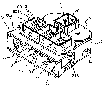
Figure 2 shows the frame element 5 on the pin side S.
The frame element 5 on the pin side S can also be
replaced by the frame element 6 on the socket side B,
however, since the plug housing 1 with the connection
modules 30 is configured in analogous fashion
substantially for the pin side S and for the socket
side B. The frame element 5 comprises a carrier element
51 and a plurality of accommodating chambers 50,
through which the carrier element 51 passes. The
carrier element 51 is used substantially for fastening
the frame element 5 on the plug housing 1. The
accommodating chambers 50 are used for accommodating
the wear modules 31, which are inserted into the
contact chamber 50 along the insertion direction F. In
the present exemplary embodiment, three accommodating
chambers 50 are arranged next to one another in a row,
in a similar fashion to the plug housing 1, and an
individual accommodating chamber 50' is arranged offset
towards the rear with respect to this row. The
accommodating chambers 50 are delimited substantially
by a side wall 52a, b. In this case, the side wall 52a,
b comprises an upper side wall region 52a, which
extends from the carrier element 51 upwards (away from
the plug housing 1 if connected to the plug housing 1),
and a lower side wall region 52b, which extends from
the carrier element 51 downwards (in the direction of
the plug housing 1) . The lower side wall region 52b is
in engagement with the opening 16 in the plug housing 1
in the fitted state.
The accommodating chambers 50 furthermore comprise
latching elements 53, which are preferably configured
as peripheral ribs in the accommodating chamber 50. The
wear modules 31 preferably comprise peripheral cutouts
310, which can also be referred to as grooves. As can
be seen from figure 2, the wear modules 31 are inserted
into the accommodating chambers 50 from above and then
latched in in self-latching fashion with the aid of the
CA 02702725 2010-04-13
WO 2009/059440 - 17 - PCT/CH2008/000434
latching elements 53 and peripheral cutouts 310. Owing
to the elasticity of the wear modules 31, said wear
modules can be inserted and latched into the
accommodating chamber 50 with a low amount of force
expenditure. Preferably, the wear modules are provided
with the electrically conductive elements 7 prior to
being inserted into the accommodating chamber 50.
In the assembled state, subregions, in this case the
lower side wall region 52b, of the accommodating
chambers 50 protrude into a complementary opening or
step 16 in the plug housing 1. As a result, the frame
element 5 is centered relative to the plug housing 1.
The frame element 6 for accommodating the wear modules
32 on the socket side B is designed to be substantially
identical, wherein the reference symbols begin with the
number 6.
Figure 3 shows the plug according to the invention from
above and serves to illustrate the position of the
sections of the sectional illustrations shown in
figures 4a, 4b, 4c and 4d.
Figure 4a shows a sectional illustration of the plug
along the section line 4a-4a in figure 3. In this case,
the plug on the pin side S is connected to the plug on
the socket side B.
The sectional illustration illustrates the arrangement
of the plug modules 3 with the connection modules 30
and the wear modules 31, 32. The electrically
conductive elements are not shown in this illustration,
with reference being made to figure 4b in this regard.
It can be seen from figure 4a that the connection
modules 30 are guided in the contact chamber 10 through
the guides 11. In addition, a channel 15 is
illustrated, through which the cable can leave the plug
CA 02702725 2010-04-13
WO 2009/059440 - 18 - PCT/CH2008/000434
body 1 in order to be connected to a peripheral device.
The connection modules 30 are therefore accommodated by
the contact chamber 10 of the plug housing 1.
The connection modules 30 and also the wear modules 31
are designed to be substantially right-parallelepipedal
in the present exemplary embodiment. In this case,
openings 303, 313, 323 extend through this
right-parallelepipedal body, wherein the openings 303,
313, 323 are used to accommodate the electrically
conductive elements 7 (later referred to as pin
elements 70, socket elements 71 and connection elements
72). In addition, the openings 303, 313, 323 have
cutouts (flutes, grooves) and the pin elements 70, the
socket elements 71 and the connection elements 72 have
elevations (flutes, grooves) which are complementary to
the cutouts and are in engagement with the cutouts.
Alternatively, the cutouts can also be arranged in the
pin elements 70, the socket elements 71 and the
connection elements 72 and the elevations can be
arranged in the openings 303, 313, 323.
The sectional illustration likewise shows that the
frame element 5 comprises the wear modules 31 for the
pin side S. In the general form it can be said that the
frame elements 5, 6 accommodate the wear modules 31,
32. In addition, reference is made here to the fact
that the surface 311 of the wear modules 31 is located
completely in the frame element 5.
The wear modules 32 for the socket side B are arranged
in the frame element 6.
This sectional illustration clearly shows that the plug
housing 1 with the contact chambers 10 and the
connection modules 30 on the socket side B and the plug
side S are configured substantially identically. The
plug side S and the socket side B accordingly differ
CA 02702725 2010-04-13
WO 2009/059440 - 19 - PCT/CH2008/000434
substantially in the configuration of the wear modules
31 for the pin side S and the wear modules 32 for the
socket side 32, and the two frame elements 5 and 6.
In the present exemplary embodiment shown in figure 4a,
parts of the frame elements 5, 6, namely the side walls
52b, 62b, which extend from the carrier element 51, 61
in the direction of the plug housing 1, protrude into
the plug housing 1. It is likewise shown that the parts
of the side edges 52a, 62a, which extend away from the
plug housing 1, are configured in such a way that the
side wall 52a of the frame element 5 protrudes into the
side wall 62a of the frame element 6. The two plugs on
the pin side and the socket side are guided
mechanically relative to one another over these side
walls 52a, 62a, which protrude one inside the other.
Optionally, the frame element 5, 6 can comprise a
peripheral groove 56 in the region of the lower side
wall 52, which groove 56 can accommodate a seal 8 (for
example an 0 ring) . The seal 8 seals off the frame
element 5, 6 in this region with respect to the plug
housing 1 and at the same time ensures good centering.
Figure 4b substantially serves the purpose of
explaining the electrically conductive contact between
the pin side S and the socket side B. The electrically
conductive element arranged in the wear element 31 on
the pin side S is referred to as the electrically
conductive pin element 70 here. The electrically
conductive element arranged in the wear module 31 is
referred to as the electrically conductive socket
element 71 here. The electrically conductive elements
arranged in the two connection modules 30 are referred
to as the electrically conductive connection elements
72.
CA 02702725 2010-04-13
WO 2009/059440 - 20 - PCT/CH2008/000434
The connection element 72 has a substantially
cylindrical configuration and has latching-in elements
720 on the cylindrical surface, with which latching-in
elements 720 the connection element 72 can latch into
complementary elements in the corresponding opening in
the connection module 30. On the side facing the wear
module 31, 32, the connection element 72 comprises a
cylindrical opening 721, also referred to as a blind
hole, for accommodating a pin or a journal of the pin
element 70 or the socket element 71, which is arranged
opposite the connection element 73 in the wear module
31, 32. In other words, this means that cylindrical
parts of the pin element 70 or the socket element 71
protrude into the blind hole 721. On the side facing
the channel 15, the connection element 72 comprises a
connection point 722, to which the braided wires of a
cable can be connected, as described above.
In alternative embodiments it is also conceivable for
the connection element 72 not to be designed to have a
cylindrical opening 721, but to have a cylindrical
journal. In this case, the pin elements 70 or the
socket elements 71 would then be configured to have a
blind hole in the corresponding section. This means
that the structure of the connection between the
connection element 72 and the pin element 70 or the
connection element 72 and the socket element 71 can
also be exchanged.
The pin element 70 is likewise configured so as to be
substantially cylindrical and also has latching
elements 700, with which the pin element 70 can latch
into complementary elements in the opening of the wear
module 31. The pin element 70 has a length which is
greater than the height of the wear element 31, i.e. in
the latched-in state, the pin element 70 protrudes
beyond the wear module 31 on both sides. On the side
facing the connection module 30, the pin element 70 is
CA 02702725 2010-04-13
WO 2009/059440 - 21 - PCT/CH2008/000434
configured so as to have a cylindrical contact section
701. The contact section 701 protrudes into the
cylindrical opening 721 of the connection element 72.
As a result, an electrical contact between the
connection element 72 and the pin element 70 is
provided. On the side facing the socket side B, the pin
element 70 likewise has a cylindrical contact section
702. The contact section 702 is used for the
electrically conductive connection to the socket
element 71.
The socket element 71 is designed to be substantially
identical to the pin element 70 in the region which is
in engagement with the connection element 72. In the
region which faces the wear element 31 on the pin side
S, the socket element 71 comprises a cylindrical
opening 710 (for example a blind hole), which is used
for accommodating the contact section 702 of the pin
element 70. Likewise, the socket element 71 is
configured in such a way that it does not protrude out
of the wear module 31 towards the pin side S.
When the frame element 5, 6 is assembled with the plug
housing, the connection elements 72 are electrically
conductively connected to the corresponding socket
elements 71 and pin elements 70, respectively. As soon
as the two plugs on the pin side S and on the socket
side B are connected to one another, the socket
elements 71 on the socket side B and the pin elements
70 on the pin side S are electrically conductively
connected to one another.
The connection direction of the plug on the socket side
B to the plug on the pin side S is along the direction
F, which is preferably at an angle, in particular at
right angles, with respect to the insertion direction E
of the connection modules 30. In other words, it can
also be said that the connection direction is
CA 02702725 2010-04-13
WO 2009/059440 - 22 - PCT/CH2008/000434
substantially parallel to the insertion direction of
the frame element 5, 6 into the plug housing 1. In the
connected state, the surface 311 of the wear element 31
is arranged opposite the surface 321 of the wear
element 32. The pin elements 70 on the pin side S in
this case protrude into the wear elements 31 on the
socket side B.
The configuration of the pin elements 70, the socket
elements 71 and the connection elements 72 enables
particularly flexible and simple handling when
replacing one of the elements. Owing to the fact that
the wear modules 31 with the frame elements 5, 6 can be
separated from the plug housing 1, this can also be
referred to as a sandwich-like construction.
This illustration 4b also shows the fitting of the plug
according to the invention. By way of preparation, the
connection modules 30 are equipped with the connection
elements 72, which are then connected to a peripheral
device. Likewise by way of preparation, the
corresponding wear modules 31, 32 are equipped with the
pin elements 70 and the socket elements 71,
respectively. In a first step, the connection modules
30 are inserted into the corresponding contact chamber
10 along the insertion direction E. In a second step,
the wear modules 31, 32 are inserted and latched into
their corresponding accommodating chamber 50, 60 in the
frame element 5, 6. As the final step, the frame
elements 5, 6 are connected to the plug housing 1 along
the connection direction F, wherein at the same time an
electrically conductive contact between the connection
elements 72 and the pin elements 70 or between the
connection elements 72 and the socket elements 71 is
produced. The frame elements 5, 6 can additionally be
connected to the plug housing 1 with fastening means,
in particular with a screw-type connection.
CA 02702725 2010-04-13
WO 2009/059440 - 23 - PCT/CH2008/000434
Alternatively, a latch-in connection can also be
provided.
Figures 4c and 4d show a section through the plug
according to the invention along the section lines
4c-4c and 4d-4d, respectively. In this case, figure 4c
shows the pin side and figure 4d shows the socket side
B. The electrically conductive connecting elements are
not shown in this illustration.
Figure 4d illustrates an interspace Z between the wear
element 32 and the side wall 62a. This interspace Z
serves the purpose of accommodating the side wall 52a
of the other frame element 5, as described previously.
These two sectional illustrations likewise show that
the openings in the connection modules 30, the wear
modules 31, 32 comprise different cutouts 312, 322 for
accommodating the latching elements of the electrically
conductive contact elements 7, 70, 71, 72. These
cutouts 312, 322 have been described previously as
elements which are complementary to the latching
elements.
Figure 5 shows a view of the assembled plug with the
pin side S and the socket side B. In the present
exemplary embodiment, both the plug on the pin side S
and the plug on the socket side B comprise an identical
number of plug modules 3. In alternative embodiments,
as are illustrated in figures 6-9, for example, a plug
housing can also be designed to have only one plug
module. The design of these plugs is substantially
identical to the designs described above.
Figure 6 shows a perspective view of the pin side S of
a plug with only one plug module 3. The design of this
plug is substantially similar to the exemplary
embodiments already described above, and therefore only
CA 02702725 2010-04-13
WO 2009/059440 - 24 - PCT/CH2008/000434
brief details are given of this embodiment at this
juncture.
Figure 7 illustrates the socket side B of a plug with
only one plug module 3 in an exploded illustration. The
plug housing 2 comprises a contact chamber 20, which
serves the purpose of accommodating the connection
element 30. The contact chamber 20, as has already been
described above, is equipped with guide elements 200
and latching elements 201. The contact chamber 20 is
delimited by side walls 202. The connection element 30
can likewise be inserted into the contact chamber 20
along an insertion direction E. The frame element 9 is
likewise designed to be identical to the frame elements
5, 6 which have already been described above. In this
case, it comprises an accommodating chamber 90, which
serves the purpose of accommodating a wear module 31,
32. The cable guide and the other features are
configured analogously to the above-described exemplary
embodiments. In addition, a coating described below can
also be provided.
Figure 8 comprises the combination of a plug housing
with a plug module (pin side S) and a plug housing with
four plug modules (socket side B), of which three are
arranged in a row and one is arranged outside of this
row. This shows the varied and modular application of
the present invention since it is possible for the
plugs to be combined with one another in a variety of
ways. Alternatively, a plug which comprises a plurality
of, in particular three, contact chambers arranged in a
row can also be provided. Other arrangements of the
contact chambers are likewise conceivable. For example,
it is conceivable to have a configuration which
comprises three contact chambers arranged next to one
another in a first row and two contact chambers
arranged in a second row, wherein the second row is
arranged behind the first row.
CA 02702725 2010-04-13
WO 2009/059440 - 25 - PCT/CH2008/000434
Preferably, the surface of the contact chambers 10,
10', 20 is coated with a metallic coating. In addition,
the accommodating chambers 50, 60 can also be coated
with a metallic coating on the inner side 501 and/or on
the outer side 502. The metallic coating acts as a
shield and can therefore prevent crosstalk between the
individual plug modules 3. As a result, a first plug
module can transmit control signals for a motor or
another actuator, for example, and a module which is
directly adjacent to said first plug module can
transmit electrical power for the actuator. A coating
consisting of aluminum oxide, copper, copper/chromium
is preferably used as the metallic coating.
By coating the surface of the side wall 52a, which
faces the side wall 62a, and by coating the surface of
the side wall 62a, which faces the surface of the side
wall 52a, the shielding effect can be further improved.
In addition, it is conceivable for these two surfaces
to come into electrical contact with one another.
As is shown by way of example in the sectional
illustrations in figures 4a and b, the frame element
with the protruding-in side walls 52a and 62a provides
extensive and continuous shielding by virtue of the
coating of the relevant surface. As a result, a plug
module 3 can be shielded successfully and efficiently
from a further plug module 3. Preferably, the coating
is in this case arranged in such a way that the coating
of the contact chamber 10 can be electrically connected
to the coating of the accommodating chamber 50, 60. In
addition, parts of the opening 16 or the entire surface
of the opening 16 can also be provided with a coating.
Preferably, the coatings of adjacent contact chambers
are DC-connected to one another. In alternative
exemplary embodiments, it is also conceivable for the
CA 02702725 2010-04-13
WO 2009/059440 - 26 - PCT/CH2008/000434
individual coatings of the contact chambers to be
DC-isolated from one another.
If the cable which is connected to the corresponding
connection module 30 has a dedicated shield, this
shield should be guided so far into the contact chamber
that the shield cannot become detached.
Alternatively, the shield can be connected to a
connection element 72, for example, and can be guided
10 via the corresponding plug module, via the pin elements
'70 and the socket elements 71, from the socket side B
to the plug side S. In this case, the shield of the
cable on the socket side B has the same voltage
potential as the shield of the cable on the pin side S.
Alternatively, the shield of the cable can also be
connected to the electrochemical coating of the contact
chamber 10. For example, it is conceivable to connect
the shield of the cable to the surface coating by means
of a screw or a soldered joint via contact chamber 10.
Preferably, the parts of the plug module 3, i.e. the
connection module 30 and the wear modules 31, 32, are
dimensioned in such a way that they have lateral play
in the contact chamber 10 or in the accommodating
chamber 50, 60. Preferably, each of the modules can be
moved in each lateral axis through 0.25 mm to 0.5 mm.
The lateral axes can best be seen in figure 3. In this
case, the X axis and the Y axis, which is perpendicular
thereto, are understood as the lateral axes. In other
words, this means that each of the connection modules
30 and the wear modules 31, 32 can be moved from one
end position into another end position through a
maximum of 0.5 mm, i.e. for example from -X to +X.
However, owing to the play, an angular rotation through
the Y axis or through the X axis is also possible. By
virtue of the provision of such large interspaces,
angle errors can also be efficiently compensated for
when the pin side is plugged together with the socket
CA 02702725 2010-04-13
WO 2009/059440 - 27 - PCT/CH2008/000434
side. Likewise, corresponding play needs to be provided
between the frame elements 5, 6 on the pin side S and
on the socket side B. As a result of the play provided
and as a result of the elasticity, angle errors and
lateral positional errors can be compensated for. In
addition, the pin element 70, the socket elements and
the connection elements 72 can comprise angled bevels
or chamfers in the relevant regions, which bevels or
chamfers facilitate the assembly of the elements.
Alternatively, a contact chamber 10, which is not used
for producing an electrical contact, can also be
tightly sealed by a closure element.
CA 02702725 2010-04-13
WO 2009/059440 - 28 - PCT/CH2008/000434
List of reference symbols
S Plug pin side
B Plug socket side
E Insertion direction
1 Plug housing (plurality of plug modules)
2 Plug housing (one plug module)
3 Plug module
5 Frame element pin side
6 Frame element socket side
7 Electrically conductive elements
8 Sealing element
9 Frame element (plug-in module)
10 Contact chamber
100 Guide elements
101 Latching elements
102 Side walls
103 Side walls
13 Opening
14 Opening
15 Channel
16 Opening/Step
Connection module
30' Connection module
30 31 Wear module for pins
32 Wear module for sockets
301 Cutouts
302 Guide cutouts
303 Openings for accommodating electrically
conductive elements
310 Peripheral cutout
CA 02702725 2010-04-13
WO 2009/059440 - 29 - PCT/CH2008/000434
311 Surface of wear module for pins
312 Cutouts
313 Openings for accommodating electrically
conductive elements
321 Surface of wear module for sockets
322 Cutouts
323 Openings for accommodating electrically
conductive elements
50 Accommodating chamber
51 Carrier element
52a Side wall top
52b Side wall bottom
53 Latching elements
501 Outer side
502 Inner side
60 Accommodating chamber
61 Carrier element
62a Side wall top
62b Side wall bottom
63 Latching elements
70 Electrically conductive pin element
71 Electrically conductive socket element
72 Electrically conductive connection element
700 Latching elements
701 Contact section
702 Contact section
710 Cylindrical opening
721 Cylindrical opening
722 Connection point