Language selection

Search

Patent 2702744 Summary

Third-party information liability

Some of the information on this Web page has been provided by external sources. The Government of Canada is not responsible for the accuracy, reliability or currency of the information supplied by external sources. Users wishing to rely upon this information should consult directly with the source of the information. Content provided by external sources is not subject to official languages, privacy and accessibility requirements.

Claims and Abstract availability

Any discrepancies in the text and image of the Claims and Abstract are due to differing posting times. Text of the Claims and Abstract are posted:

  • At the time the application is open to public inspection;
  • At the time of issue of the patent (grant).
(12) Patent: (11) CA 2702744
(54) English Title: DOOR LOCK
(54) French Title: VERROU DE PORTE
Status: Granted
Bibliographic Data
(51) International Patent Classification (IPC):
  • E05B 47/02 (2006.01)
  • H01F 7/18 (2006.01)
(72) Inventors :
  • KERVINEN, PASI (Finland)
  • JURVANEN, MARKKU (Finland)
  • PURMONEN, MIKA (Finland)
(73) Owners :
  • ABLOY OY (Finland)
(71) Applicants :
  • ABLOY OY (Finland)
(74) Agent: KIRBY EADES GALE BAKER
(74) Associate agent:
(45) Issued: 2019-06-11
(86) PCT Filing Date: 2008-11-06
(87) Open to Public Inspection: 2009-05-28
Examination requested: 2013-02-07
Availability of licence: N/A
(25) Language of filing: English

Patent Cooperation Treaty (PCT): Yes
(86) PCT Filing Number: PCT/FI2008/050636
(87) International Publication Number: WO2009/066003
(85) National Entry: 2010-04-13

(30) Application Priority Data:
Application No. Country/Territory Date
20075822 Finland 2007-11-20

Abstracts

English Abstract


In an embodiment according to the invention, the controller for
a solenoid in an electromechanical lock is arranged to generate motion power
to move the solenoid plunger and holding power to hold the solenoid plunger
in place so that the motion power generated consists of a higher power level
and a lower power level that are alternating.


French Abstract

L'invention porte, selon un mode de réalisation, sur un contrôleur pour un électroaimant dans un verrou électromécanique qui est agencé pour générer une puissance de mouvement afin de déplacer le noyau plongeur de l'électroaimant et maintenir la puissance afin de tenir le noyau plongeur de l'électroaimant en place de sorte que la puissance de mouvement générée est constituée d'un plus haut niveau de puissance et d'un plus bas niveau de puissance qui alternent.

Claims

Note: Claims are shown in the official language in which they were submitted.


6

Claims

1. A controller of a solenoid of an electromechanical lock, wherein the
solenoid
has a solenoid plunger and generates motion power to move the solenoid plunger
and
holding power to hold the solenoid plunger in place, levels of said powers
being created
by pulse-width modulation,
characterised in that the motion power to be generated is comprised of a
higher
power level and a lower power level that are alternating, said higher and
lower power
levels being created by pulse-width modulation, and
the holding power is generated to be at a constant power level to cause the
solenoid to hold the solenoid plunger in place.
2. The controller according to Claim 1, characterised in that the motion
power
comprises three higher power level ranges and two lower power level ranges,
said
motion power starting in the higher power level range.
3. The controller according to Claim 1 or 2, characterised in that the
duration of the
higher power level is 25 to 35 ms and the duration of the lower power level is

15 to 25 ms.
4. The controller according to any one of Claims 1 to 3, characterised in
that the
motion power is arranged to be repeated at intervals.
5. An electromechanical lock comprising a solenoid and a controller of the
solenoid,
wherein the controller of the solenoid is as defined in any one of Claims 1 to
4.
6. A door lock according to Claim 5, characterised in that the controller
of the
solenoid is a processor or an electric circuit.

Description

Note: Descriptions are shown in the official language in which they were submitted.


CA 02702744 2016-09-01
1
DOOR LOCK
Field of Technology
The invention relates to an electromechanical lock equipped with a solenoid.
The solenoid's operation is controlled with a controller.
Prior Art
Electromechanical locks often use a solenoid to control deadbolting means in
the lock so that the lock is locked into the deadbolted position or the
deadbolting
means are released from the deadbolted position. A solenoid is also used to
link the
handle to the other parts of the lock.
A typical solenoid comprises a coil fitted into a ferromagnetic body. A
solenoid
plunger, which is a metal rod, is located inside the coil and moved by means
of a
magnetic field generated around the coil. The movement of the solenoid plunger
is
utilised in lock mechanisms to achieve the desired action.
The operation of the solenoid is controlled by a controller also known as a
solenoid controller. The purpose of the controller is to reduce the current
consumption
of the solenoid. Figure 1 illustrates the current curve of a typical solenoid
controlled by
a controller. It is evident from the figure that at first, motion power 1 is
routed to the
solenoid to generate a sufficiently strong magnetic field to move the solenoid
plunger.
After a certain time, once the plunger has moved to the desired position, the
current
going through the solenoid is driven to holding power 2. Holding power is
required to
hold the solenoid plunger in the desired position as a solenoid typically
employs a
return spring to return the solenoid plunger to the initial position when the
solenoid is
unenergised. The total period of motion power and holding power is dimensioned
to be
sufficient for normal operation such as opening the door and/or turning the
handle. The
use of holding power reduces the current consumption of the solenoid. It is
desirable
to dimension the return spring to be as stiff as possible as confidence about
the state
of the unenergised solenoid is desired. More energy is required to put the
solenoid
plunger and the associated lock mechanism into motion compared to the energy

2
=
required to hold it in place. The return spring is dimensioned with regard to
the holding
power in order to allow the solenoid to overcome the force of the return
spring in all
situations.
US 2003/0016102 discloses a known embodiment for actuating the solenoid.
By changing the resistance of the solenoid's circuit, holding current and
motion current
are provided. The holding and motion currents are kept within a certain range
in order
to prevent undesirable heating of the solenoid.
Electromechanical locks have relatively little space for the different
components
of the lock. Smaller electromechanical locks in particular require the use of
smaller
solenoids due to lack of space. However, the solenoid must be sufficiently
large to
generate the required power. Thus the problem (particularly with small
solenoids) is
that the solenoid must generate sufficient power while maintaining reasonable
current
consumption.
Short Description of Invention
The objective of the invention is to reduce the disadvantages of the problem
described above.
In an embodiment according to the invention, the controller of a solenoid of
an
electromechanical lock is arranged to generate motion power to move the
solenoid
plunger and holding power to hold the solenoid plunger in place so that the
motion
power generated is comprised of a higher power level and a lower power level
that are
alternating. Thus the motion power is pulsating power that aims to overcome
the friction
forces working against the movement of the solenoid plunger. Pulsating motion
power
consumes less current than steady motion power.
In a particular embodiment the invention provides a controller of a solenoid
of
an electromechanical lock, wherein the solenoid has a solenoid plunger and
generates
motion power to move the solenoid plunger and holding power to hold the
solenoid
plunger in place, levels of said powers being created by pulse-width
modulation,
characterised in that the motion power to be generated is comprised of a
higher power
level and a lower power level that are alternating, said higher and lower
power levels
CA 2702744 2017-09-06

CA 02702744 2016-09-01
3
being created by pulse-width modulation, and the holding power is generated at
a
substantially constant power level to cause the solenoid to hold the solenoid
plunger in
place.
.. List of Figures
In the following, the invention is described in more detail by reference to
the
enclosed drawings, where
Figure 1 illustrates an example of a prior art lock solenoid controller
current
curve,
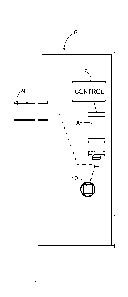
Figure 2 illustrates an example of a lock solenoid controller current curve
according to the invention, and
Figure 3 illustrates a simplified example of an embodiment according to the
invention.
.. Description of the Invention
Figure 2 illustrates a solenoid controller current curve according to the
invention,
in which the motion power 3 consists of a higher power level 4 and a lower
power level
5. The power can be represented, for example, with the formula P = Ul, in
which U is
voltage and I is current. When the voltage and/or current level is varied, the
power level
also varies. This text speaks of power levels but it is clear that the desired
power level
can be implemented by controlling the voltage or current. The power levels 4,
5 are
alternating, creating a variable power range 3. A pulsating force is imposed
on the
solenoid plunger within this power range. Pulsating power helps to overcome
friction
forces. The locking mechanism may be loaded (for example, door sealing
strips), which
.. makes it more difficult to put the solenoid plunger in motion. In other
words, the
solenoid plunger can be put in motion with less power if alternately repeating
levels of
motion power are used.
The period of motion power is dimensioned so that the solenoid plunger can be
moved to the desired position. Approximately 130 ms is appropriate for most
.. applications. It is preferable that the motion power range 3 starts with a
higher power

CA 02702744 2016-09-01
4
level. For example, three higher power levels and two lower power levels,
among which
the first level is a higher power level, constitute a very well-functioning
solution. The
duration of the higher power level 4 can be, for example, 25 to 35 ms, and the
duration
of the lower power level 5 can be 15 to 25 ms. In practice, periods of
approximately
130 ms (or another period of motion power) can be repeated as desired, for
example at
intervals of 1 second or 3 seconds. This is convenient, for example, when a
user is
pressing the lock handle, preventing the solenoid plunger from moving. In this
case, the
solenoid will not warm up excessively because the duration of the higher power
level is
limited and it is repeated at certain intervals, while the user may have
ceased pressing
the handle.
Figure 3 illustrates a simplified example of equipment according to the
invention, in which the electrochemical lock 6 comprises a solenoid 8 and a
solenoid
controller 7. The solenoid is arranged to control either the bolt 9 or the
functional
linkage between the lock handle and the rest of the lock mechanism 10. The
controller
7 is arranged to generate the motion power consisting of alternating power
levels as
described above. In handle-controlled locks, when the handle is pressed and
the
solenoid 8 receives a control command, the link between the handle and the
rest of the
mechanism is more secure when the handle is released. The solenoid operating
voltage is normally 10 to 30 volts direct current. The operating voltage is
modified by
pulse-width modulation (PWM), for example, which creates the desired current
and
power level.
The solenoid controller 7 is a processor within the lock, for example. It can
also
be an electric circuit customised for the purpose.
Because variable-level motion power consumes less power than steady motion
power at a high level, energy is saved. This also allows a smaller solenoid to
more
securely move the desired lock mechanisms. The load on the power supply is
also
smaller. Variable-level motion power allows the use of a stronger spring
pulled by the
solenoid. The return spring can be dimensioned in accordance with the motion
power.
Repeating the motion power will correct any changes in state. This makes lock
operation more reliable. Also, the solenoid will not warm up unnecessarily.

CA 02702744 2016-09-01
As can be noted, an embodiment according to the invention can be achieved
through many different solutions. It is thus evident that the invention is not
limited to the
examples mentioned in this text, and the claims should not be limited to the
exemplified
embodiments. The claims should be given the broadest interpretation consistent
with
5 the description as a whole.

Representative Drawing
A single figure which represents the drawing illustrating the invention.
Administrative Status

For a clearer understanding of the status of the application/patent presented on this page, the site Disclaimer , as well as the definitions for Patent , Administrative Status , Maintenance Fee  and Payment History  should be consulted.

Administrative Status

Title Date
Forecasted Issue Date 2019-06-11
(86) PCT Filing Date 2008-11-06
(87) PCT Publication Date 2009-05-28
(85) National Entry 2010-04-13
Examination Requested 2013-02-07
(45) Issued 2019-06-11

Abandonment History

There is no abandonment history.

Maintenance Fee

Last Payment of $473.65 was received on 2023-10-10


 Upcoming maintenance fee amounts

Description Date Amount
Next Payment if standard fee 2024-11-06 $624.00
Next Payment if small entity fee 2024-11-06 $253.00

Note : If the full payment has not been received on or before the date indicated, a further fee may be required which may be one of the following

  • the reinstatement fee;
  • the late payment fee; or
  • additional fee to reverse deemed expiry.

Patent fees are adjusted on the 1st of January every year. The amounts above are the current amounts if received by December 31 of the current year.
Please refer to the CIPO Patent Fees web page to see all current fee amounts.

Payment History

Fee Type Anniversary Year Due Date Amount Paid Paid Date
Application Fee $400.00 2010-04-13
Maintenance Fee - Application - New Act 2 2010-11-08 $100.00 2010-09-09
Maintenance Fee - Application - New Act 3 2011-11-07 $100.00 2011-07-13
Maintenance Fee - Application - New Act 4 2012-11-06 $100.00 2012-10-11
Request for Examination $800.00 2013-02-07
Maintenance Fee - Application - New Act 5 2013-11-06 $200.00 2013-10-24
Maintenance Fee - Application - New Act 6 2014-11-06 $200.00 2014-10-27
Maintenance Fee - Application - New Act 7 2015-11-06 $200.00 2015-10-26
Maintenance Fee - Application - New Act 8 2016-11-07 $200.00 2016-10-26
Maintenance Fee - Application - New Act 9 2017-11-06 $200.00 2017-10-25
Maintenance Fee - Application - New Act 10 2018-11-06 $250.00 2018-10-24
Final Fee $300.00 2019-04-17
Maintenance Fee - Patent - New Act 11 2019-11-06 $250.00 2019-10-17
Maintenance Fee - Patent - New Act 12 2020-11-06 $250.00 2020-10-15
Maintenance Fee - Patent - New Act 13 2021-11-08 $255.00 2021-10-13
Maintenance Fee - Patent - New Act 14 2022-11-07 $254.49 2022-10-12
Maintenance Fee - Patent - New Act 15 2023-11-06 $473.65 2023-10-10
Owners on Record

Note: Records showing the ownership history in alphabetical order.

Current Owners on Record
ABLOY OY
Past Owners on Record
JURVANEN, MARKKU
KERVINEN, PASI
PURMONEN, MIKA
Past Owners that do not appear in the "Owners on Record" listing will appear in other documentation within the application.
Documents

To view selected files, please enter reCAPTCHA code :


To view images, click a link in the Document Description column. To download the documents, select one or more checkboxes in the first column and then click the "Download Selected in PDF format (Zip Archive)" or the "Download Selected as Single PDF" button.

List of published and non-published patent-specific documents on the CPD .

If you have any difficulty accessing content, you can call the Client Service Centre at 1-866-997-1936 or send them an e-mail at CIPO Client Service Centre.


Document
Description 
Date
(yyyy-mm-dd) 
Number of pages   Size of Image (KB) 
Abstract 2010-04-13 2 55
Claims 2010-04-13 1 27
Drawings 2010-04-13 2 13
Description 2010-04-13 4 170
Representative Drawing 2010-04-13 1 5
Cover Page 2010-06-08 1 28
Description 2016-09-01 5 184
Claims 2016-09-01 1 31
Drawings 2016-09-01 2 13
Claims 2013-02-07 1 28
Description 2013-02-07 4 174
Claims 2015-03-09 1 32
Description 2015-03-09 5 192
Amendment 2017-09-06 5 163
Description 2017-09-06 5 173
Claims 2017-09-06 1 29
Drawings 2017-09-06 2 12
Examiner Requisition 2018-02-06 5 239
Amendment 2018-08-03 3 131
PCT 2010-04-13 4 107
Assignment 2010-04-13 4 85
PCT 2010-04-14 6 219
Final Fee 2019-04-17 2 51
Representative Drawing 2019-05-09 1 2
Cover Page 2019-05-09 1 27
Prosecution-Amendment 2013-02-07 5 185
Prosecution-Amendment 2014-09-11 3 96
Prosecution-Amendment 2015-03-09 6 187
Examiner Requisition 2016-03-29 3 209
Amendment 2016-09-01 10 330
Examiner Requisition 2017-03-07 4 212