Language selection

Search

Patent 2703195 Summary

Third-party information liability

Some of the information on this Web page has been provided by external sources. The Government of Canada is not responsible for the accuracy, reliability or currency of the information supplied by external sources. Users wishing to rely upon this information should consult directly with the source of the information. Content provided by external sources is not subject to official languages, privacy and accessibility requirements.

Claims and Abstract availability

Any discrepancies in the text and image of the Claims and Abstract are due to differing posting times. Text of the Claims and Abstract are posted:

  • At the time the application is open to public inspection;
  • At the time of issue of the patent (grant).
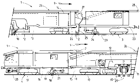
(12) Patent: (11) CA 2703195
(54) English Title: A METHOD AND MACHINE FOR CONSOLIDATION OF BALLAST OF A TRACK
(54) French Title: PROCEDE ET MACHINE DE COMPACTAGE DE BALLAST DE VOIE FERREE
Status: Granted and Issued
Bibliographic Data
(51) International Patent Classification (IPC):
  • E01B 27/17 (2006.01)
  • E01B 27/20 (2006.01)
(72) Inventors :
  • THEURER, JOSEF (Austria)
  • WOERGOETTER, HERBERT (Austria)
(73) Owners :
  • FRANZ PLASSER BAHNBAUMASCHINEN-INDUSTRIEGESELLSCHAFT MBH
(71) Applicants :
  • FRANZ PLASSER BAHNBAUMASCHINEN-INDUSTRIEGESELLSCHAFT MBH (Austria)
(74) Agent: RICHES, MCKENZIE & HERBERT LLP
(74) Associate agent:
(45) Issued: 2015-05-12
(86) PCT Filing Date: 2008-10-17
(87) Open to Public Inspection: 2009-06-04
Examination requested: 2013-06-13
Availability of licence: N/A
Dedicated to the Public: N/A
(25) Language of filing: English

Patent Cooperation Treaty (PCT): Yes
(86) PCT Filing Number: PCT/EP2008/008797
(87) International Publication Number: WO 2009068139
(85) National Entry: 2010-04-21

(30) Application Priority Data:
Application No. Country/Territory Date
A 1923/2007 (Austria) 2007-11-27

Abstracts

English Abstract


Consolidation of ballast (2) of a track (3) is carried out in two steps, after
cleaning by means of a cleaning machine (4). To that end, cleaned ballast is
discharged, thus forming a first ballast layer (29). The track (3), laid upon
the
same, is set in transverse oscillations by a front stabilising unit (24), and
thus
the first ballast layer (29) is consolidated. With the aid of a second chute
(25),
a second ballast layer (30) is formed which is subsequently consolidated by
means of a rear stabilising unit (18).


French Abstract

La présente invention concerne le compactage de ballast (2) d'une voie ferrée (3), compactage qui a lieu après un nettoyage en deux étapes effectué par une machine de nettoyage (4). A cette fin, du ballast nettoyé est éjecté puis utilisé pour former une première couche de ballast (29). La voie ferrée (3) posée sur cette couche est déplacée selon des oscillations transversales par un module de stabilisation avant (24) et compacte ainsi la première couche de ballast (29). Une seconde goulotte (25) permet de former une seconde couche de ballast (30) qui est ensuite compactée par un module de stabilisation arrière (18).

Claims

Note: Claims are shown in the official language in which they were submitted.

6
CLAIMS
1. A method for consolidation of ballast of a ballast bed of a track (3),
in
which the ballast is discharged and consolidated while the track (3) is
lifted,
wherein the track (3) is set in horizontal transverse oscillations while under
a
vertical load, characterized by the following method steps:
a) after formation of a first ballast layer (29), the track (3) is laid
upon the
first ballast layer (29) and set in horizontal transverse oscillations while
under a vertical load,
b) for forming a second ballast layer (30), the track (3) is lifted and
additional ballast (2) is discharged,
c) the track (3) is tamped and
d) set in horizontal transverse oscillations while under a vertical load.
2. A machine for consolidation of ballast of a ballast bed of a track (3),
including a stabilising unit (18) for applying a vertical load in connection
with
transverse oscillations of the track (3), a tamping unit (11) and a lifting
unit
(10), wherein a second stabilising unit (24) precedes the tamping unit (11)
with regard to a working direction (9), and that a ballast chute (25) for
discharging ballast (2) is arranged between the second stabilising unit (24)
and the track lifting unit (10).
3. A machine according to claim 2, characterized in that a conveyor belt
(26), extending in the longitudinal direction of the machine, for ballast
transport in the working direction (9) of the machine (1) is provided above
the
stabilising unit (18), the tamping unit (11) and the second stabilising unit
(24)
and that a deflection device (27) for selectively deflecting the ballast (2)
from
the conveyor belt (26) into the ballast chute (25) is arranged above the
ballast
chute (25).

Description

Note: Descriptions are shown in the official language in which they were submitted.


CA 02703195 2010-04-21
1
A METHOD AND MACHINE FOR CONSOLIDATION OF
BALLAST OF A TRACK
[0001] The invention relates to a method for consolidation of ballast of a
ballast
bed of a track, in which the ballast is discharged and consolidated while
the track is lifted, wherein the track is set in horizontal transverse
oscillations while under a vertical load, and to a machine.
[0002] Since after ballast cleaning, for example according to US 4 770
104, the ballast bed is formed entirely anew, said ballast bed is
completely uncompacted. For this reason also, it is absolutely
mandatory to follow up the track position correction, carried out with
the aid of tamping tools, with a consolidation of the ballast bed. To
that end, the track is loaded with a static vertical load and, parallel
thereto, is set in horizontal transverse oscillations. This so-called
stabilisation of the track is accomplished by well-known track
stabilizers (for example, US 5 257 579).
[0003] According to GB 2 267 305, it is known to set a track lifting unit of a
cleaning machine in transverse oscillations. With this, there is the
possibility of lowering any ballast accumulations, caused by
irregular ballast discharge, in order to achieve a more uniform
vertical position of the track.
[0004] It is the object of the present invention to provide a method or a
machine
of the specified type with which an improved consolidation of the ballast
bed can be achieved.

CA 02703195 2014-12-12
2
. .
[0005] According to the invention, this object is achieved with a method or a
machine of the specified type as described herein.
[0006] Due to the features according to the invention, it is now possible to
significantly improve the penetration effect of the track stabilisation. As
a consequence of introducing the ballast in layers, the ballast
compression resulting from the transverse oscillations of the track can
be achieved also in deeper layers of the ballast bed. Thus, the ballast
bed can be compacted in an overall more homogenous way for a more
durable track position.
[0006a] Accordingly, in one aspect the present invention resides in a method
for consolidation of ballast of a ballast bed of a track, in which the
ballast is discharged and consolidated while the track is lifted, wherein
the track is set in horizontal transverse oscillations while under a
vertical load, characterized by the following method steps: a) after
formation of a first ballast layer, the track is laid upon the first ballast
layer and set in horizontal transverse oscillations while under a vertical
load, b) for forming a second ballast layer, the track is lifted and
additional ballast is discharged, c) the track is tamped and d) set in
horizontal transverse oscillations while under a vertical load.
[0006b] In another aspect, the present invention resides in a machine for
consolidation of ballast of a ballast bed of a track, including a
stabilising unit for applying a vertical load in connection with
transverse oscillations of the track, a tamping unit and a lifting unit,
wherein a second stabilising unit precedes the tamping unit with
regard to a working direction, and that a ballast chute for discharging
ballast is arranged between the second stabilising unit and the track
lifting unit.
[0007] Additional advantages of the invention become apparent from the
following description and drawings.

CA 02703195 2014-12-12
2a
[0008] The invention will be described in more detail below with reference to
embodiments represented in the drawing in which
[0009] Fig. 1 shows a simplified side view of a machine for ballast
consolidation and a cleaning machine,
[0010] Figs. 2 and 3 each show an enlarged side view of a front and rear
section, respectively, of the machine for ballast consolidation, and
[0011] Fig. 4 shows a variant of a machine combination for cleaning and
consolidation of the ballast bed.
[0012] Shown in Fig. 1 is a machine 1 for consolidation of ballast 2 of a
track
3 as well as a cleaning machine 4. The latter is equipped with a ballast
pick-up chain 5, a screening plant 6 and a discharge belt 7. A chute 8
is provided for introducing additional or new ballast.

CA 02703195 2010-04-21
3
[0013] The machine 1 (see Figs. 2, 3) for consolidation of the ballast 2 is
situated
¨ with regard to a working direction 9 ¨ immediately behind the cleaning
machine 4 and is equipped with a track lifting- and tamping unit 10, 11.
The two units 10, 11 are arranged on a satellite 12 which is displaceable
relative to a machine frame 13. A reference system 14 is provided for
correction of the track position.
[0014] Articulatedly connected to a rear end 15 of the machine frame 13 is a
rear
frame part 16 which has a first or rear stabilising unit 18 located between
two undercarriages 17. For producing horizontal transverse oscillations,
said stabilising unit 18 is connected to an eccentric drive 19 and may be
brought into form-fitting engagement with rails 20 of the track 3 by means
of roller clamps. Drives 21 arranged between the frame part 16 and the
stabilising unit 18 serve for applying vertical static loads upon the track 3.
[0015] Articulatedly connected to a front end 22 of the machine frame 13 is a
front
frame part 23 which is connected to a second or front stabilising unit 24.
The latter precedes the tamping unit 11 ¨ with regard to the working
direction 9 ¨ and is configured just like the already described first
stabilising unit 18.
[0016] Arranged between the front, second stabilising unit 24 and the track
lifting
unit 10 is a ballast chute 25 for discharging the ballast 2. A conveyor belt
26, extending in the longitudinal direction of the machine, for ballast
transport in the working direction 9 of the machine 1 is provided above the
tamping- and stabilising units 11, 18, 24. Located above the ballast chute
25 is a deflection device 27 for selectively deflecting the ballast 2 from the
conveyor belt 26 into the ballast chute 25. A front discharge end 28 of the

CA 02703195 2010-04-21
4
conveyor belt 26 projects beyond the front frame part 23 in such a way
that new ballast 2 (see Fig. 1) can be transported onto a conveyor belt and
into the chute 8 of the cleaning machine 4, as desired.
[0017] The method according to the invention will be described in more detail
below: A first ballast layer 29 is formed by discharging upon the track 3 the
ballast 2 which has been cleaned in the screening plant 6. The track 3,
which is laid upon the first ballast layer 29 by a lifting device (not shown)
of
the cleaning machine 4, is set in horizontal transverse oscillations under
vertical load with the aid of the front stabilising unit 24. As a result, the
first
ballast layer 29 is consolidated. =
[0018] Parallel thereto, new ballast 2 is continuously supplied from storage
wagons (not shown) to the conveyor belt 26 which spans the entire
machine 1. The ballast 2 is transported in the working direction 9 of the
machine 1 and, in dependence upon the deflection device 27, discharged
into the ballast chute 25 and, if desired, also into the chute 8 of the
cleaning machine 4.
[0019] The ballast 2 discharged via the ballast chute 25 forms a second
ballast
layer 30, with the track 3 being lifted by the trailing track lifting unit 10.
After tamping by the tamping unit 11, the track 3 is again loaded with a
vertical load with the aid of the rear stabilising unit 18 and simultaneously
set in horizontal transverse oscillations. Thus, the second or upper ballast
layer 30 is consolidated.
[0020] During the entire working operation, the train formation - consisting
of the
machine 1 for two-step ballast consolidation and the cleaning machine 4 -
travels continuously in the working direction 9. As a consequence of a

CA 02703195 2010-04-21
relative displacement of the tamping- and the track lifting unit 11, 10,
cyclical tamping of the track 3 is possible parallel to the continuous forward
travel.
[0021] A variant of the invention, indicated schematically in Fig. 4, differs
in that
the front frame part 23 is connected to the cleaning machine 4.
Additionally, the ballast 2 for both the first and the second ballast layer
29,
30 is supplied from the screening plant 6.

Representative Drawing
A single figure which represents the drawing illustrating the invention.
Administrative Status

2024-08-01:As part of the Next Generation Patents (NGP) transition, the Canadian Patents Database (CPD) now contains a more detailed Event History, which replicates the Event Log of our new back-office solution.

Please note that "Inactive:" events refers to events no longer in use in our new back-office solution.

For a clearer understanding of the status of the application/patent presented on this page, the site Disclaimer , as well as the definitions for Patent , Event History , Maintenance Fee  and Payment History  should be consulted.

Event History

Description Date
Maintenance Request Received 2021-08-12
Common Representative Appointed 2019-10-30
Grant by Issuance 2015-05-12
Inactive: Cover page published 2015-05-11
Inactive: Reply to s.37 Rules - PCT 2015-02-20
Pre-grant 2015-02-20
Inactive: Final fee received 2015-02-20
Notice of Allowance is Issued 2015-01-30
Letter Sent 2015-01-30
Notice of Allowance is Issued 2015-01-30
Inactive: QS passed 2015-01-19
Inactive: Approved for allowance (AFA) 2015-01-19
Amendment Received - Voluntary Amendment 2014-12-12
Maintenance Request Received 2014-08-20
Inactive: S.30(2) Rules - Examiner requisition 2014-07-30
Inactive: Report - No QC 2014-07-24
Maintenance Request Received 2013-08-08
Letter Sent 2013-06-28
Request for Examination Received 2013-06-13
Request for Examination Requirements Determined Compliant 2013-06-13
All Requirements for Examination Determined Compliant 2013-06-13
Inactive: Cover page published 2010-06-15
Inactive: Notice - National entry - No RFE 2010-06-09
Inactive: First IPC assigned 2010-06-08
Inactive: IPC assigned 2010-06-08
Application Received - PCT 2010-06-08
National Entry Requirements Determined Compliant 2010-04-21
Application Published (Open to Public Inspection) 2009-06-04

Abandonment History

There is no abandonment history.

Maintenance Fee

The last payment was received on 2014-08-20

Note : If the full payment has not been received on or before the date indicated, a further fee may be required which may be one of the following

  • the reinstatement fee;
  • the late payment fee; or
  • additional fee to reverse deemed expiry.

Please refer to the CIPO Patent Fees web page to see all current fee amounts.

Fee History

Fee Type Anniversary Year Due Date Paid Date
MF (application, 2nd anniv.) - standard 02 2010-10-18 2010-04-21
Basic national fee - standard 2010-04-21
MF (application, 3rd anniv.) - standard 03 2011-10-17 2011-08-16
MF (application, 4th anniv.) - standard 04 2012-10-17 2012-08-22
Request for examination - standard 2013-06-13
MF (application, 5th anniv.) - standard 05 2013-10-17 2013-08-08
MF (application, 6th anniv.) - standard 06 2014-10-17 2014-08-20
Final fee - standard 2015-02-20
MF (patent, 7th anniv.) - standard 2015-10-19 2015-08-18
MF (patent, 8th anniv.) - standard 2016-10-17 2016-08-08
MF (patent, 9th anniv.) - standard 2017-10-17 2017-09-11
MF (patent, 10th anniv.) - standard 2018-10-17 2018-08-20
MF (patent, 11th anniv.) - standard 2019-10-17 2019-08-26
MF (patent, 12th anniv.) - standard 2020-10-19 2020-08-07
MF (patent, 13th anniv.) - standard 2021-10-18 2021-08-12
2022-08-23 2022-08-23
MF (patent, 14th anniv.) - standard 2022-10-17 2022-08-23
MF (patent, 15th anniv.) - standard 2023-10-17 2023-08-17
Owners on Record

Note: Records showing the ownership history in alphabetical order.

Current Owners on Record
FRANZ PLASSER BAHNBAUMASCHINEN-INDUSTRIEGESELLSCHAFT MBH
Past Owners on Record
HERBERT WOERGOETTER
JOSEF THEURER
Past Owners that do not appear in the "Owners on Record" listing will appear in other documentation within the application.
Documents

To view selected files, please enter reCAPTCHA code :


To view images, click a link in the Document Description column. To download the documents, select one or more checkboxes in the first column and then click the "Download Selected in PDF format (Zip Archive)" or the "Download Selected as Single PDF" button.

List of published and non-published patent-specific documents on the CPD .

If you have any difficulty accessing content, you can call the Client Service Centre at 1-866-997-1936 or send them an e-mail at CIPO Client Service Centre.


Document
Description 
Date
(yyyy-mm-dd) 
Number of pages   Size of Image (KB) 
Cover Page 2015-04-22 1 48
Description 2010-04-21 5 162
Abstract 2010-04-21 1 14
Claims 2010-04-21 2 42
Drawings 2010-04-21 2 44
Representative drawing 2010-06-10 1 5
Cover Page 2010-06-15 1 38
Description 2014-12-12 6 187
Claims 2014-12-12 1 37
Representative drawing 2015-01-20 1 17
Notice of National Entry 2010-06-09 1 210
Reminder - Request for Examination 2013-06-18 1 118
Acknowledgement of Request for Examination 2013-06-28 1 177
Commissioner's Notice - Application Found Allowable 2015-01-30 1 162
PCT 2010-04-21 5 193
Fees 2011-08-16 1 51
Fees 2012-08-22 1 55
PCT 2013-08-08 1 56
Fees 2014-08-20 1 53
Correspondence 2015-02-20 1 58
Maintenance fee payment 2021-08-12 1 25