Note: Descriptions are shown in the official language in which they were submitted.
CA 02703249 2010-04-21
WO 2009/060729 PCT/JP2008/069295
1
Description
Threaded Joint for Steel Pipes
Technical Field
This invention relates to a threaded joint for use in connecting steel pipes
such
as oil country tubular goods (OCTG) which include tubing and casing primarily
used
for the exploration and production of oil wells and gas wells, riser pipes,
line pipes,
and the like. More particularly, the present invention relates'to a threaded
joint for
steel pipes of the type having a sealing surface and a shoulder surface in
addition to a
threaded portion and which has excellent sealing properties against internal
and
io external pressure and excellent compression resistance when repeatedly
subjected to
combined loads.
Background Art
Technology used for connecting steel pipes used in equipment of the oil
production industry such as oil country tubular goods, riser pipes, and line
pipes
includes threaded joints. Threaded joints for steel pipes are constituted by a
pin
having a male thread element provided at the end of a first tubular member and
a box
which is a female thread element provided at the end of a second tubular
member.
The joint is tightened by engaging the male thread and the female thread.
Standard threaded joints are prescribed by API (American Petroleum Institute)
standards but in recent years, the environments for exploration and production
of
crude oil and natural gas are becoming more severe. As a result, there is
increasing
use of high performance special joints referred to as premium joints which are
not
prescribed by API standards.
In a typical premium joint, in addition to a tapered thread for firmly
connecting steel pipes, the pin and the box have sealing surfaces which can
form a
metal-to-metal seal for providing sealing performance and torque shoulder
surfaces
for acting as stoppers during tightening (make-up).
In the past, since vertical wells were predominant, it was sufficient for a
CA 02703249 2010-04-21
WO 2009/060729 PCT/JP2008/069295
2
threaded joint for OCTG to resist the tensile load due to the weight of pipes
and to
prevent leakage of high pressure fluid passing through it. However, in recent
years,
wells are becoming deeper, and deviated wells and horizontal wells which bend
underground are increasing, and the development of wells in difficult
environments
such as in the sea or in polar regions is increasing. Therefore, the
properties required
for threaded joints are becoming more varied and more strict as exemplified by
resistance to compression, resistance to bending, ability to seal against
external
pressure, and ease of use in the field.
As a result, qualification tests for threaded joints are becoming more severe.
io In the Series A test of recent ISO 13679 standards; alternances of internal
pressure
and external pressure combined with tension or compression (internal pressure
+
tension, internal pressure + compression, external pressure + tension, and
external
pressure + compression) (herein referred to as repeated combined loads) are
applied
three times. Such severe test conditions were not taken into consideration in
the past
in the development of threaded joints.
As shown in Figure 2, a typical premium joint has a structure in which an
unthreaded portion 12 referred to as a lip portion is provided at the end of a
threaded
portion having a tapered male thread 11 provided on a pin 1 which is a male
threaded
element. A sealing surface 13 for forming a metal-to-metal seal is provided on
the
outer peripheral surface of the lip portion. A torque shoulder surface 14 is
provided
on the end surface of the lip portion (and accordingly on the end surface of
the pin).
Naturally, a box 2 which is a corresponding female threaded element is
provided with a female thread 21, a sealing surface 23, and a shoulder surface
24 at
the rear of the box which correspond to or mate with the male thread 11, the
`sealing
surface 13, and the end surface shoulder surface 14, respectively, of the pin
1.
An overlap in the radial direction referred to as interference is provided
between the sealing surfaces of the pin and the box. This type of threaded
joint is
designed so that if the joint is tightened until the shoulder surfaces of the
pin and the
box contact each other, the sealing surfaces of both members are in intimate
contact
3o around their entire periphery and sealing is provided by metal-to-metal
contact.
The above-described sealing performance is exhibited to the highest degree
CA 02703249 2010-04-21
WO 2009/060729 PCT/JP2008/069295
3
when tightening is carried out with a suitable torque in the period from when
the
shoulders abut until the shoulders begin to undergo plastic deformation (when
a
normal tightened state occurs).
The shoulder surfaces act not only as stoppers for tightening but also act to
bear almost all of a compressive load acting on the joint. Therefore, if the
shoulder
surfaces are not thick or if the shoulders are not stiff, they cannot
withstand a large
compressive load.
Prior art for increasing the resistance to external pressure and resistance to
compression of a premium joint is described in WO 2004/109173 (Patent Document
io 1). That threaded joint greatly increases resistance to external pressure
by providing
a portion which does not contact the box (referred to below as a nose portion)
between the shoulder surface and the sealing surface of the end surface of the
pin. At
the same time, the taper angle of the nose portion is made 0 degrees (a
cylindrical
surface) or is made smaller than that of the sealing surface. Due to the
provision of
the nose portion, a decrease in the thickness of the end surface shoulder
surface is
prevented, and an increase in resistance to compression can be achieved.
However, in the threaded joint described in Patent Document 1, when a high
compressive force and external pressure are simultaneously applied, and when a
tensile force and internal pressure are subsequently simultaneously applied,
it has
been found by the inventors that there can be a risk of developing a leak.
WO 00/08367 (Patent Document 2) discloses a threaded joint in which a tight
contacting region is provided in two locations of a lip portion, namely, a
tight
contacting region near the threaded portion is defined as a sealing surface
and a tight
contacting region near the end surface (shoulder surface) is defined as a
protecting
portion. The protecting portion which is a second contact region provided in a
location close to the end of the lip portion has the object of supplying a
first seal to
internal pressure (and thus to protect the sealing surface) and to optimize
the forces
and moments undergone by the lip.
In the threaded joint described in Patent Document 2, the amount of
interference of the protecting portion is set to be higher than the amount of
interference of the sealing surface (at least 1.15 times and at most 1.3
times) in order
CA 02703249 2010-04-21
WO 2009/060729 PCT/JP2008/069295
4
to retain a sufficient amount of contact pressure on the protective portion
while a
moderate contact pressure is obtained on the sealing surface. In addition, as
Patent
Document 2 incites to set sufficient distances from the shoulder to the
protective
portion, from the protective portion to the sealing surface and from the
sealing
surface to the thread, the lip portion is designed to be extremely long, so a
sufficient
thickness (radial dimension) of the shoulder surface may not be obtained. As a
result, when a high compressive load is applied, the joint may not
sufficiently
withstand the compressive load, and it is thought that its compressive
performance
may be inadequate.
DE 4446806 (Patent Document 3) discloses a threaded joint of the same type
as disclosed in Patent Document 2.
U.S. Patent No.4,473,245 (Patent Document 4) discloses a threaded joint in
which a metal-to-metal seal is provided on the exterior of the pipe and a
torque
shoulder provides an additional metal-to-metal seal. In the threaded joint
disclosed
is in Patent Document 4, however, the thickness of a lip portion is designed
to be very
thin, so it is difficult to ensure the resistance to high external pressure
and high
compression.
U.S. Patent No.3,489,437 (Patent Document 5) discloses a threaded joint in
which a metal-to-metal seal and a shoulder are provided. However, in the
threaded
joint disclosed in Patent Document 5, the lip portion is designed according to
the
same rule as a typical premium joint in Figure 2, so it is not considered to
ensure the
resistance to high external pressure and high compression.
U.S. Patent No. 3,870,351 (Patent Document 6) discloses a threaded joint
characterized by its shoulder surfaces having a particular profile. In the
threaded
joint disclosed in Patent Document 6, the shoulder surfaces are rounded
profiles (the
shoulder surface of one of the pin and box being convex and that of the other
being
concave), and they function to form a second seal. This structure is intended
to
equalize the contact between the sealing surfaces of the first seal by
suppressing
misalignment or the flexure of the lip toward the pipe axis at the time of
make-up.
However, in a threaded joint disclosed in Patent Document 6, although
equalization of the sealing contact or sealing pressure of the first seal is
taken into
CA 02703249 2010-04-21
WO 2009/060729 PCT/JP2008/069295
account, it is out of consideration to use the threaded joint in a situation
where a high
compression force and high external pressure simultaneously act thereon. As
shown
in Figure 7 of this patent document, there is a space between the outer side
of the
concave shoulder surface of the box and the outer edge of the convex shoulder
5 surface of the pin. In a situation where a high tension force and high
external
pressure act thereon, the shoulder surfaces of pin and box can separate easily
due to
the high tensional force and the tip of lip can easily be deformed or be moved
towards the outer side (that is, in the direction which expands the diameter).
Therefore, in a threaded joint disclosed in Patent Document 6, it is difficult
to control
io and suppress the deformation or movement of the tip of the pin towards the
outer
side as described above. Furthermore, if the shoulder surface of the pin has a
convex
profile, the innermost edge part of the shoulder surface of the box which is
concave
is so thin that the shoulder surface of the box tends to undergo a heavy
plastic
deformation when a high compression load is applied to the joint.
Patent Document 1: WO 2004/109173
Patent Document 2: WO 00/08367
Patent Document 3: DE 4446806
Patent Document 4: U.S. Patent No. 4,473,245
Patent Document 5: U.S. Patent No. 3,489,437
Patent Document 6: U.S. Patent No. 3,870,351
Disclosure of Invention
The object of this invention is to provide a premium-type threaded joint for
steel pipes which solves the problems of the above-described prior art and
which has
excellent resistance to compression and which can greatly increase overall
sealing
performance when subjected to repeated combined loads.
As disclosed in Patent Document 1, it is known that resistance to external
pressure is greatly improved in a premium-type threaded joint for steel pipes
by
providing a nose portion which does not contact the box between the sealing
surface
of the lip portion and the end surface shoulder surface of a pin.
However, when a high torque or a high compressive load acts on the threaded
CA 02703249 2010-04-21
WO 2009/060729 PCT/JP2008/069295
6
joint having a nose portion, the joint may sometimes develop leaks. The
inventors
have found after thorough studies that a reason for developing leaks is linked
to the
long nose portion which is not supported and can move in the radial direction
(the
direction perpendicular to the joint axis); the shoulder surface at the end
surface of
the lip portion of the pin thus unstably deforms in this direction, plastic
deformation
develops due to bending of the entire lip portion, involving a risk for the
sealing
performance produced by the metal-to-metal contact of the sealing surfaces
located
near the threads to be impaired. Accordingly, in order to obtain good sealing
properties stably against internal and external pressure in a threaded joint
for steel
io pipes having a nose portion, a structure which prevents unstable
deformation of the
shoulder surface of the lip portion of the pin is necessary. Furthermore, in
order to
prevent unstable deformation while maintaining torque resistance and good
sealing
properties against internal and external pressure, a structure which
guarantees the
length of the pin lip portion and the thickness of the shoulder surface is
necessary.
According to the present invention, deformation in the radial direction of the
end surface shoulder surface of the pin lip portion can be suppressed by
making a
main portion of the shoulder surface (referred to below as the main shoulder
surface)
to have a shape to cope with deformation towards the inner surface and by
providing
a sub shoulder as a secondary shoulder to cope with deformation towards the
outer
surface. Namely, the shoulder surface is immobilized so that deformation does
not
occur towards either the inner surface or the outer surface. In order to
maintain good
resistance to compression, most of the thickness of the pin shoulder surface
is
occupied by the main shoulder having a gentle slope with the perpendicular
surface
of the axial direction of the joint. The sub shoulder receives substantially
no
compressive load, and it is sufficient for it to stop deformation in the
outward radial
direction of the end of the pin. Therefore, the thickness of the sub shoulder
is
preferably as small as possible. Only when high compressive load acts on the
threaded joint between the pin and the box, the shoulder surface of the pin is
stably
supported by the shoulder surface of the box by abutment of both the main
shoulders
3o and the sub shoulders, and unstable deformation in the radial direction of
the end of
the lip portion is prevented, thereby ensuring good resistance to compression.
CA 02703249 2010-04-21
WO 2009/060729 PCT/JP2008/069295
7
The present invention is a threaded joint for steel pipes comprising a pin and
a
box, the pin having a male thread and a lip comprising (i) a sealing surface
and (ii) a
nose portion provided with a shoulder surface, the box having a female thread,
a
sealing surface and a shoulder surface, the male thread being interengaged
with the
female thread, the sealing surface of the pin being in sealing contact with
the
corresponding sealing surface of the box, the shoulder surface of the pin
being
arranged at an end face of the pin, the sealing surface of the pin being
located on a
pipe end side near the male thread, the nose portion existing between the
sealing
surface and the shoulder surface, said nose portion not contacting a portion
of the
io box facing said the nose portion of the pin,
characterized in that the shoulder surface of the pin comprises two distinct
adjacent surfaces, main shoulder in the inner side and sub shoulder in the
outer side,
and in that the corresponding shoulder surface of the box facing the shoulder
surface
of the pin comprises two distinct adjacent surfaces, main shoulder in the
inner side
and sub shoulder in the outer side, said main shoulder surfaces of the pin and
box
being disposed such as to prevent a radially inward deformation of the lip
end, said
sub shoulder surfaces of pin and box being disposed such as to limit a
radially
outward deformation of the lip end, said main shoulder of the pin having a
greater
radial dimension than said sub shoulder of the pin, at least said main
shoulder surface
of the pin being in axial abutment with at least the corresponding main
shoulder
surface of the box.
Here, "the shoulder surface of the pin comprises two distinct adjacent
surfaces" means that the angles of main shoulder surface and sub shoulder
surface
with regard to a plane perpendicular to the axis of the threaded joint are
distinctly
different.
In preferred embodiments of the present invention the main shoulder surface
of the pin is a reverse shoulder surface having a negative angle with respect
to a
plane perpendicular to the joint axis and sub shoulder surface has a positive
angle.
"The main shoulder surface of the pin is a reverse shoulder surface having a
3o negative angle with respect to a plane perpendicular to the joint axis"
means a
shoulder surface having an angle of slope such that the innermost portion of
the main
CA 02703249 2010-04-21
WO 2009/060729 PCT/JP2008/069295
8
shoulder surface is to the rear of the outermost portion (the portion
adjoining the sub
shoulder surface) in the advancing direction of the pin in tightening the
threaded
joint. Similarly "sub shoulder surface has a positive angle" means sub
shoulder
surface having an angle of slope with respect to its reference angle such that
the
outermost portion of the sub shoulder surface is to the rear of the innermost
portion
(the portion adjoining the main shoulder surface) in the advancing direction
of the
pin in tightening the threaded joint. These angles of slope are then in a
range
between -90 and +90 degrees.
In a preferred embodiment of the present invention, only the main shoulder
io surface of the pin is in axial abutment with the corresponding main
shoulder surface
of the box. There is then no substantial tight contact and more preferably no
contact
at all between sub shoulders of the pin and the box. Sealing performance
between
sealing surface of the pin and the box is accomplished more effectively.
In another preferred embodiment, at least a part of the nose portion of the
pin
has an outside peripheral surface which is not in prolongation of the sealing
surface
of the pin. "At least a part of the nose portion has an outside peripheral
surface
which is not in prolongation of the sealing surface" means that the shape of
the
outside surface of a part or the whole of the nose portion is substantially
different
from that of the sealing surface.
Said part of the nose portion having a different shape from the sealing
surface
is preferably a region extending for at least half the length in the axial
direction of the
nose portion and is thus named a main part of the nose portion. For example,
said
(main) part of the nose portion can be a cylindrical surface which is not
sloped with
respect to the axial direction, or it can be a tapered surface with a small
angle of
slope. A region which is the remainder of the nose portion is preferably a
region
shorter than half the axial length, and it may have the same shape as the
sealing
surface (namely, it may be an extension of the sealing surface).
In other preferred embodiments, the absolute value of the angle of the main
shoulder surfaces of the pin and the box is from 5 to 25 degrees with respect
to a
plane perpendicular to the joint axis (namely, the angle of the main shoulder
surface
of the pin is in the range from -5 to -25 degrees), and the angle of slope of
their sub
CA 02703249 2010-04-21
WO 2009/060729 PCT/JP2008/069295
9
shoulder surfaces are from 5 to 30 degrees with respect to the joint axis
(from +60 to
+85 degrees with respect to a plane perpendicular to the joint axis), and the
angle of
slope of the sealing surfaces of the pin and the box is in the range of 5 to
25 degrees
with respect to the joint axis. The angle of slope of the sub shoulder
surfaces (with
reference to the joint axis) is preferably larger than the angle of slope of
the sealing
surfaces. As a result, even if the shoulder surface deforms in the axial
direction, a
decrease in the sealing performance due to deformation of the sealing surface
is
prevented.
In order to increase resistance to compression, it is advantageous that the
io thickness (radial dimension) of the shoulder surface at the end of the pin
be made as
large as possible and that the cross section of the portions closer to the end
than the
sealing surface (namely, the nose portion) be made as large as possible. To
this end,
in its main part as defined hereabove, the nose portion preferably has a
smaller slope
than the slope of the sealing surface and the sub shoulder surface with
respect to the
joint axis. Specifically, the shape of the outer surface of the main part of
the nose
portion of the pin can be made a cylindrical surface (with a slope of 0
degrees with
respect to the joint axis) or a frusto-conical surface having a slope with
respect to the
joint axis which is smaller than the slope of the sealing surface or the sub
shoulder
surface with reference to the same axis.
If the outer surface of the nose portion contacts the inner surface of the box
after tightening of the threaded joint, there is a risk for the sealing
performance of the
joint being damaged. Therefore, in order to prevent this contact with
certainty, a gap
(radial distance between non contacting surfaces) of at least 0.1 mm is
preferably
provided between these surfaces in the above-described main region of the nose
portion. The inner surface of the box in this region preferably has a shape
similar to
that of the nose portion of the pin, and the gap between the two is preferably
made
uniform in the main region.
As aforementioned in the explanation of "at least a part of the nose portion
has
an outside peripheral surface which is not in prolongation of the sealing
surface", a
partial surface of the nose portion of the pin adjoining the sealing surface
may have
the same slope as the sealing surface.
CA 02703249 2010-04-21
WO 2009/060729 PCT/JP2008/069295
The junction between the sub shoulder surface and the main shoulder surface
of the pin preferably forms a rounded apex having a radius of at most 1.5 mm.
The sealing surfaces of the pin and the box may both be a frusto-conical
surface, but making one of the sealing surfaces a frusto-conical surface and
the other
5 sealing surface a curved surface of rotation (torical surface) having a
radius of
curvature of at least 20 mm or a combination of a curved surface of rotation
and a
frusto-conical surface increases the sealing performance of the joint.
The sub shoulder surfaces of both the pin and the box are preferably frusto-
conical surfaces. The main shoulder surfaces of both the pin and the box are
io preferably frusto-conical surfaces, but it is also possible for one to be a
projecting
curved surface (convex torical surface) and the other to be a recessed curved
surface
(concave torical surface) or a combination of such curved surfaces with planar
surfaces as disclosed in WO 2007/017082. As an alternative, the main shoulder
surfaces may have a stepped shape as disclosed in US 4,611,838, such step
shape
preventing an inward deformation of the pin end.
The thickness (radial dimension) of the main shoulder surface is preferably at
least 1.5 times the thickness of the sub shoulder surface.
In a premium-type threaded joint for steel pipes according to the present
invention, a nose portion which does not contact the box is provided at the -
end of the
lip portion of a pin, and the shape of the shoulder surfaces of the end
surfaces thereof
is made a double-shoulder structure having a main shoulder surface and a sub
shoulder surface, whereby good compressive performance is obtained. As a
result,
the sealing performance when a combined load is repeatedly applied is greatly
increased, and leaks no longer occur in a Series A test according to ISO 13679
standards.
Brief Description of the Drawings
Figure 1 is a schematic cross-sectional view of the vicinity of the lip
portion of
a threaded joint for steel pipes according to the present invention in which
the main
portion of the nose portion is a frusto-conical surface.
Figure 2 is a schematic cross-sectional view of a typical premium joint for
CA 02703249 2010-04-21
WO 2009/060729 PCT/JP2008/069295
11
OCTG of the conventional coupling type, (A) being a partial view showing only
one
side, and (B) being a view of the entirety.
Figure 3 is a schematic cross-sectional view of a threaded joint for steel
pipes
according to the present invention.
Figure 4 is a schematic cross-sectional view of the vicinity of the lip
portion of
a threaded joint for steel pipes according to the present invention in which
the main
portion of the nose is a cylindrical surface.
Figure 5 is a schematic cross-sectional view of the shape of a thread.
Figures 6(A) to 6(D) are schematic diagrams illustrating grooves formed on
io the shoulder surface of a pin. Figure 6(A) is a partial perspective view,
Figures 6(B)
- 6(C) are end views, and Figure 6(D) shows an axial profile of a pin and a
box near
the end of the pin.
Figures 7 and 8 show grooves formed on the shoulder surface of a pin.
Best Mode for Carrying Out the Invention
Below, a threaded joint for steel pipes according to this invention will be
explained while referring to the drawings.
Figures 1, 3, and 4 are schematic cross-sectional views of a threaded joint
for
steel pipes according to the present invention. This threaded joint is one
type of
premium-type threaded joint comprising a pin 1 and a box 2. Accordingly, the
pin 1
comprises a threaded portion having a male thread 11, and a lip portion 12
situated
on the front end side of the threaded portion and having a sealing surface 13.
A
shoulder surface is provided on the end surface of the tip of the lip portion.
As
shown in these figures, the sealing surface 13 of the pin 1 is usually
positioned
adjoining or in the vicinity of the threaded portion of the lip portion 12.
The box 2
has a threaded portion having a female thread 21 which meshes with the male
thread
11 of the pin 1, a sealing surface 23 which can sealingly contact the sealing
surface
13 of the pin (to achieve a metal-to-metal contact seal), and a shoulder
surface which
contacts the shoulder surface of the pin in the axial direction of the joint.
As shown in Figure 5, the male thread 11 of the pin I and the female thread 21
of the box 2 are both tapered threads, with the diameter of the thread crest
and the
CA 02703249 2010-04-21
WO 2009/060729 PCT/JP2008/069295
12
thread root gradually decreasing towards the end of the pin. Similarly, the
sealing
surfaces 13 and 23 of the pin I and the box 2 are tapered surfaces which
decrease in
diameter towards the end of the pin.
A portion of the male thread closer to the tip of the threaded portion of the
pin
1 (the side adjoining the lip portion 12) may be a non-engaging thread which
does
not mesh with the female thread 21 of the box 2. In this case, as shown in the
figure
3, a circumferential groove 32 is preferably formed in the portion of the box
2
opposing the non-engaging thread of the pin. In this manner, the stiffness of
the lip
is increased and the resistance of the joint to compression is increased. With
the
io same object, the wall thickness of the pin and the box may be increased
towards the
shoulder surface (the inner diameter is decreased) by swaging or upsetting.
The lip portion 12 of the pin 1 has a nose portion 16, which is a non-
contacting region which does not contact the opposing portion of the box,
between
the sealing surface 13 and the shoulder surface at its end. Therefore, the
length of the
is lip portion is increased compared to a usual premium joint shown in Figure
2 which
does not have a non-contacting region forward of the sealing surface of the
pin.
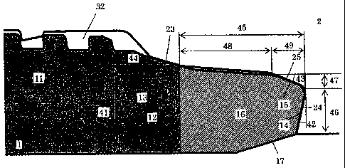
In the present invention, the end shoulder surface of the pin 1 has a two-
level
structure comprising a main shoulder surface 14 on the inner surface side of
the joint
and a sub shoulder surface 15 on the outer surface side of the joint. The
thickness 46
20 (the thickness projected on a plane perpendicular to the joint axis) of the
main
shoulder surface 14 is larger than the thickness 47 of the sub shoulder
surface 15.
The main shoulder surface 14 of the pin 1 is a reverse shoulder surface in
which the
angle 42 with respect to a plane perpendicular to the joint axis is a negative
angle.
On the other hand, the angle of the sub shoulder surface 15 with respect to a
plane
25 perpendicular to the joint axis is positive. Of course, the shoulder
surface of the box
2 which contacts the shoulder surfaces 14 and 15 of the pin 1 correspondingly
comprises a main shoulder surface 24 on the inner surface side of the joint
and a sub
shoulder surface 25 on the outer surface side of the joint.
With a usual premium joint, compressive performance of approximately 40 to
3o 60% of the yield strength of the pipe body is demanded, and in some oil
wells,
compressive performance exceeding 80% is necessary. Of course, a compressive
CA 02703249 2010-04-21
WO 2009/060729 PCT/JP2008/069295
13
load is borne not only by the shoulders but also by the threaded portions, and
if
threads having a good ability to bear a compressive load are used, the load on
the
shoulders can be decreased to that extent. However, the lip portion thickness
41 (the
wall thickness of the pin at the middle of the sealing surface 13) is made at
least 25%
and preferably at least 50% of the wall thickness of the pipe body so that the
lip
portion will have the resistance to compression demanded of it.
The greater are the thicknesses of the sealing surface and the nose portion of
the lip portion, the greater is their ability to seal against external
pressure, so when a
chamfer 17 is formed on the inner surface of the end of the lip portion in
order to
io prevent turbulence by increasing circularity, the angle of the chamfer 17
with respect
to the joint axis is preferably a rather small angle in the range from 9 to 30
degrees.
Although this is not the case in Figure 1, 3 and 4, a chamfer with a shallow
angle
may similarly be provided on the inner surface of the box 2 adjoining the pin
1.
The shape of the sealing surfaces 13 and 23 of the pin 1 and the box 2 can be
made a straight line which is sloped with respect to the joint axis or a
curved line
such as a circular arc (the former will be referred to as a frusto-conical
surface and
the latter will be referred to as a curved surface of rotation), or it can be
a surface of
rotation formed by rotating a line segment which is a combination of both
lines
around the joint axis (namely, a combination of a frusto-conical surface and a
curved
surface of rotation). Preferably, the sealing surface of one of the pin 1 and
the box 2
is made a frusto-conical surface, and the sealing surface of the other is a
curved
surface of rotation or a combination of a curved surface of rotation and a
frusto-
conical surface. As a result, the sealing performance of the joint is
increased, and it
becomes difficult for galling to occur.
If the slope 44 (angle of slope) of the sealing surfaces 13 and 23 with
respect
to the joint axis is too steep, it leads to a decrease in the sealing contact
pressure at
the time of a tensile load, while if the slope is too gentle, it becomes
easier for galling
to occur due to an increase in the sliding distance. The slope angle 44 of the
sealing
surfaces is in the range from 5 to 25 degrees and preferably in the range from
10 to
20 degrees. When tapered threads are employed, the slope angle 44 of the
sealing
surfaces is larger than the slope angle of the threads 11, 21. For example,
the slope
CA 02703249 2010-04-21
WO 2009/060729 PCT/JP2008/069295
14
angle of the threads is between I to 5 degrees and preferably around 1.6
degrees.
If a reverse angle of at least a certain amount is imparted to the main
shoulder
surfaces 14 and 24 of the pin 1 and the box 2, the deformation of the lip
portion
when a compressive load is applied becomes uniform spreading in the direction
of
radially outward, and the sealing performance of the joint increases. However,
if the
reverse angle is made too large, excessive plastic deformation may occur in
the main
shoulder surface 24 of the box, thereby impairing the effect of stabilizing
deformation and decreasing the sealing performance of the joint. Therefore,
the
reverse angle 42 of the main shoulder surfaces 14 and 24 is such that the
absolute
io value of the slope 42 of the main shoulder surface 14 of the pin 1 with
respect to a
plane perpendicular to the joint axis (which is actually a negative angle) is
from 5 to
25 degrees and preferably from 10 to 20 degrees.
The sub shoulder surfaces 15 and 25 of the pin 1 and the box 2 act as stoppers
which suppress excessive outwards deformation of the end of the lip portion 12
of
the pin 1. Therefore, the sub shoulder surfaces 15 and 25 do not contact each
other
in a normal tightened state. When a high compressive load is acting or an
excessive
tightening torque is applied, they contact and suppress outwards deformation
of the
lip portion.
The geometric diametric interference (difference in diameter measured at a
reference plane before tightening the pin and box) of the sub shoulder
surfaces is
made at most 1.1 times that of the sealing surfaces, and preferably it is made
substantially equal to the geometric diametric interference of the sealing
surfaces.
The expression "substantially equal" allows a variation up to 5%.
By designing sub shoulder surfaces 15 and 25 of the pin and the box so as to
have nearly the same interference as that between the sealing surfaces 13 and
23 in a
normal tightened state, the entire lip of the pin will bends inwardly
(decrease in
diameter) due to the effect of the interference of the sealing surfaces of the
pin and
the box, and the sub shoulder surface of the pin will bend inwardly by at
least the
same amount as the interference of sealing surfaces, so contact will not take
place
3o between the sub shoulder surfaces of the pin and the box.
However, it is permissible for the sub shoulders 15 and 25 to contact each
CA 02703249 2010-04-21
WO 2009/060729 PCT/JP2008/069295
other in a normal tightened state. In this case, the contact pressure of the
sub
shoulders is made at most 50% of the contact pressure of the sealing surfaces
so as
not to have an adverse effect on sealing properties.
The normal tightened state means that the pin and box of a threaded joint are
5 tightened to reach a proper tightening torque which is prescribed by the
manufacturer
of the joint the according to the shape and material of the joint. In the
normal
tightened state, the shoulder surfaces (the main shoulder surfaces in the case
of a
threaded joint according to the present invention) of the pin and the box
contact each
other with a certain amount of interference without overall yield or extensive
plastic
io deformation.
The slope 43 of the sub shoulder surfaces 15 and 25 with respect to the joint
axis is made at least 5 degrees and at most 30 degrees (namely, the slope with
respect
to the direction perpendicular to the joint axis is at least +60 degrees and
at most +85
degrees) and is preferably greater than that of the seal (slope 44) from the
standpoints
15 of guaranteeing enough thickness of the main shoulder surfaces 14 and 24
and
suppressing deformation of the shoulder surfaces in the direction
perpendicular to the
joint axis (the radial direction).
Preferably, the sealing surface of the pin, the outside surface of the nose
portion of the pin and sub shoulder surface of the pin are not aligned and
wherein the
sealing surface of the box, the inner surface of the portion of the box facing
the
outside surface of the nose portion of the pin and the sub shoulder surface of
the box
are not aligned.
From the standpoints of maintaining resistance to compression and resistance
to torque, the thickness of the sub shoulder surface 15 of the pin 1 (the
thickness
projected on a plane perpendicular to the joint axis) is made smaller than the
thickness of the main shoulder surface 14. Preferably, the thickness of the
main
shoulder surface 14 of the pin 1 is made at least 1.5 times the thickness of
the sub
shoulder surface 15, more preferably it is made at least 2.5 times and at most
6 times,
and still more preferably it is made at least 3 times and at most 5 times.
The length 45 of the nose portion 16 of the pin 1 (namely, the length in the
axial direction of the whole nose portion, that is to say, non-contacting
region of the
CA 02703249 2010-04-21
WO 2009/060729 PCT/JP2008/069295
16
pin and the box, including sub shoulder surface region which may be in contact
with
the box) varies with the size of the threaded joint, but if it is too short,
the effect of
increasing sealing properties against the external pressure disappears, while
if it is
too long, the effect of increasing sealing properties saturates. In the range
of pipe
sizes used in OCTG (an outer diameter of approximately 50 to 550 mm), it is
preferably made approximately 4 to 20 mm.
In order to increase the resistance to compression, it is advantageous that
the
thickness of the shoulder surface of the end of the pin 1 be made as large as
possible
and that the volume of the portion of the lip portion 12 closer to the end
than the
io sealing surface 13 (namely, the nose portion 16 and the shoulder surface
14, 15) be
made as large as possible. To this end, the outer surface of the nose portion
is
preferably a cylindrical surface (having an angle of slope with respect to the
joint
axis of 0 degrees) or a frusto-conical surface having a slope with respect to
the joint
axis which is smaller than the slope of the sealing surface and the sub
shoulder over a
partial region thereof in the axial direction and preferably over a main
region having
a length of at least one half of the length in the axial direction. In this
case, the inner
surface of the portion of the box 2 opposing the nose portion 16 is preferably
made a
cylindrical surface or a frusto-conical surface (for example with the same
slope or a
substantially similar slope) like the shape of the nose portion over at least
half the
length in the axial direction so as to form a uniform gap from the outer
surface of the
nose portion.
In an embodiment in which the outer surface of the main part of the nose
portion 16 is made a frusto-conical surface (namely, a tapered surface) (shown
in
Figure 1 and Figure 3), the inner surface of the box having a frusto-conical
shape
which opposes the main part of the nose portion functions as a guide, so it
becomes
possible to perform tightening while centering the lip portion of the pin,
whereby the
sealing surfaces 13 and 23 of the pin 1 and the box 2 stably contact and the
sealing
ability is increased, and galling can be prevented. In the case that the
outside
peripheral surface of nose portion of the pin and the inner surface of the
portion of
the box opposing nose portion of the pin have a portion having a substantially
frusto-
conical shape, the taper angle of them is preferably less than 10 degree.
CA 02703249 2010-04-21
WO 2009/060729 PCT/JP2008/069295
17
On the other hand, in an embodiment in which the nose portion has a
cylindrical surface (Figure 4), the thickness (46 + 47) of the shoulder
surface and the
thickness 41 of the sealing surface 13 can be made as large as possible within
a
limited pipe wall thickness, so the resistance to compression is increased.
Even in an
embodiment in which the outer surface of the nose portion is frusto-conical,
the
thickness of the shoulder surface can be maintained close to that in an
embodiment
with a cylindrical surface by making it possible for contact to take place at
the sub
shoulder surface at the time of tightening.
If the outer surface of the nose portion of the pin contacts the inner surface
of
io the opposing surface of the box after tightening, there is the possibility
of the sealing
ability being impaired. In order to prevent this contact, the gap (radial
distance)
between the outer surface of the main part of the nose portion of the pin and
the inner
surface of the opposing portion of the box is preferably at least 0.1 mm in a
normal
tightened state of the threaded joint. The gap is preferably at most 1.0 mm
since a
too big gap may cause the inner surface of the box to lose its ability to
guide the nose
portion of the pin during tightening.
However, as shown in Figure 4, a partial region of the nose portion 16
adjoining the sealing surface 13 of the pin 1 may have the same slope as the
sealing
surface 13 (namely, it may become an extension of the sealing surface and have
a
clearly different shape from the main part of the nose portion 16 (a
cylindrical surface
in the illustrated example)) and/or a partial region adjoining the sub
shoulder surface
in the portion of the box 2 opposing the nose portion may have the same slope
as
the sub shoulder surface 25 (it may become an extension of the sub shoulder
surface
and have a clearly different shape from the inner surface of the portion of
the box
25 facing the main part of the nose portion of the pin). As a result, not only
the effect of
nose portion but also the good performance of tightening while centering the
lip
portion of the pin is accomplished. In this case as well, the main part of
nose portion
16 clearly has a different shape from the sealing surface 13 and the sub
shoulder
surface 15 on both sides thereof.
The junction between the main shoulder surface 14 and the sub shoulder
surface 15 of the pin 1 forms a rounded apex 49 with a radius of at most 1.5
mm. As
CA 02703249 2010-04-21
WO 2009/060729 PCT/JP2008/069295
18
a result, the contact area of the main shoulder surface and the sub shoulder
surface
can be maximized, and an increase in resistance to compression and suppression
of
deformation in the radial direction of the shoulder surface are achieved.
As discussed earlier, a threaded joint according to the present invention can
exhibit a high performance under compression due to a nose portion which is
provided near the tip of a lip portion of a pin so as not to contact the
opposing
surface of a box and due to a two-step shoulder structure having a main
shoulder
surface and a sub shoulder surface for the shoulder surface at the end of the
pin.
However, a greasy lubricant which is a fluid used at the time of make-up of
io the threaded joint may remain in the space 50 between the pin and the box
formed in
the area of the nose portion (hereunder, the space will be referred to as nose
space).
At the completion of make-up, the pressure in the nose space 50 is increased
by the
lubricant confined in the space, and the increased pressure may cause the
contact
pressure between the sealing surfaces 13 of the pin and the box to decrease
and thus
impair the sealing ability of the joint.
In a preferred embodiment of the present invention, the shoulder surface of at
least one of the pin and box has at least one groove or bleed concavity
extending
from the nose space to the inner surface of the threaded joint. Thus, the
groove
extends across both the main shoulder surface and sub shoulder surface of the
pin
and/or box. It is possible to locate a portion of the groove on the shoulder
surface of
the pin and the remaining portion thereof on the shoulder surface of the box.
Thus
the nose space 50 communicates with the interior space of the threaded joint
through
the groove. Therefore, when the pressure of the fluid confined in the nose
space is
increased, it can escape into the interior space of the threaded joint through
the
groove.
The fluid in the nose space can be allowed to escape by a through-hole
extending inside the shoulder portion, but the formation of such a through-
hole is
rather difficult.
In a particularly preferred embodiment, as shown in Figures 6(A) - 6(D), at
least one groove is provided on the shoulder surface of the pin.
In the case shown in Figure 6(A), the shoulder surface of the pin which is the
CA 02703249 2010-04-21
WO 2009/060729 PCT/JP2008/069295
19
end surface of the lip portion has a groove comprising two groove portions,
i.e., a
first or outer groove portion 51A and a second or inner groove portion 51B.
The
outer groove portion 51A extends obliquely across the sub shoulder surface 15,
and
the inner groove portion 51B extends obliquely across the main shoulder
surface 14.
Figure 6(B) shows an end view of the lip portion having three grooves each
having
two groove portions 51A, 51B located along the circumference of the lip end.
Figure
7 shows a photographic illustration of a pin end having a groove with such two
step
grooves on the shoulder surface.
In order to achieve the above-described function, the groove portions 51A and
io 51B must communicate with each other. To this end, as shown in Figure 6(D),
along
the innermost circumferential portion of the box shoulder which opposes the
apex 49
of the pin shoulder (the junction or interface between the main shoulder
surface and
the sub shoulder surface of the pin), a concavity 52 can be provided as a
connecting
channel so as to extend from a point opposing the inner end of the outer
groove
portion 51A to a point opposing the outer end of the inner groove portion 51B,
whereby the groove portions 51 A, 51B on the pin shoulder communicate with
each
other through the concavity 52 extending along the circumferential apex 49 on
the
box shoulder. Alternatively, this connecting channel between groove portions
51A
and 51B can be achieved by forming a chamfer or concavity on the surface of
the pin
shoulder along the circumferential apex 49 so as to extend from the inner end
of the
outer groove portion 51 A to the outer end of the inner groove portion 51 B.
More
preferably, such connecting concavity or channel can be formed on both the pin
shoulder surface and the box shoulder surface.
As shown in Figure 6(C), the outer groove portion 51A and the inner groove
portion 51B may be positioned such that they directly communicate with each
other
(namely, the inner end of the outer groove portion 51A is connected to the
outer end
of the inner groove portion 51B). Figure 8 shows a photographic illustration
of the
shoulder portion of a pin end having an outer and an inner groove portion
directly
connected to each other. This arrangement dispenses with the formation of a
connecting channel as described above, although grooving (formation of
grooves) is
somewhat easier when the outer and inner groove portions are located in the
same
CA 02703249 2010-04-21
WO 2009/060729 PCT/JP2008/069295
circumferential positions as shown in Figure 6(A). In either case, forming
grooves or
bleed concavities can be performed using an NC (numerical control) machining
system.
In another embodiment, the outer groove portion 5IA on the sub shoulder
5 surface and the inner groove portion 51B on the main shoulder surface can
extend in
a radial direction rather than in an oblique direction as shown in Figures
6(A) - 6(C),
preferably such that these two radially-extending groove portions are directly
connected to each other. In this case, the length of each groove portion is
minimized
so that fluid can escape easily, and grooves can be formed without an NC
machining
io system. However, a special groove forming machine is necessary.
In the embodiments shown in Figures 6(B) and 6(C), three grooves each
comprising an outer and an inner groove portion for establishing communication
between the nose space and the interior space of the threaded joint are
provided at
equal distances along the circumference of the shoulder surface at the pin
end. There
15 may be at least one such groove, and there is no upper limit on the number
of
grooves, although eight is enough. Preferably, the pin and/or box shoulder has
from
two to four such grooves.
The cross-sectional shape of the grooves is not restricted, but they should
have
a cross-sectional area sufficient to allow fluid to pass therethrough. The
depth of the
20 grooves is preferably at least 0.1 mm and more preferably at least 0.2 mm.
In order
to prevent a significant decrease in performance of the threaded joint under
compression due to a decrease in the contact area of the main shoulder surface
caused
by the formation of grooves, the circumferential length of each of the inner
and outer
groove portions is preferably such that each groove extends over at most 180
degrees
along the circumference of the shoulder surface. Thus, if three groove
portions are
provided on each of the main shoulder and sub shoulder as shown in Figures
6(B) or
6(C), each groove portion preferably extends along an arc with an angle of 180
degrees or less and more preferably with an angle of 120 degrees or less.
The grooves may be formed on the shoulder surface of the box instead of the
pin. When a plurality of grooves are provided in the circumferential
direction, some
of the grooves may be formed on the pin with the remaining groove or grooves
on
CA 02703249 2010-04-21
WO 2009/060729 PCT/JP2008/069295
21
the box. When a groove comprises an outer and an inner groove portion as shown
in
Figures 6(A) to 6(C), it is also possible to form the outer groove portion on
the pin
and the inner groove portion on the box, or vice versa.
The shape of a threaded joint for steel pipes other than that described above
may be the same as that of a conventional threaded joint for steel pipes of
the
premium joint type.
For example, the male thread 11 and the female thread 21 of the pin 1 and the
box 2 of a threaded joint for steel pipes according to this invention may be
tapered
threads like those of a typical conventional threaded joint for steel pipes
(such as a
io trapezoidal thread specified by an API buttress thread or a thread having
trapezoidal
shape derived from the API Buttress thread shape). There have been many
proposals
concerning the shape (for example, the angles of slope of the stabbing flank
and the
load flank of the thread, the chamfer, the gap between stabbing flanks, the
separation
between crest surfaces and root portions, and the radius of curvature of
rounded
portions) of a tapered thread for a threaded joint for steel pipes, and any of
these may
be employed. For example, although not shown in Figure 5, a chamfer (a change
in
level produced by beveling) may be provided in the stabbing flank (the side
surface
of the thread on the right side in Figure 5) of one or both of the male thread
and the
female thread.
In a tapered thread of the male thread 11 and the female thread 12, the crest
surface and the root portion of each crest can be made parallel to the taper
of the
tapered thread, but preferably they are made parallel to the axial direction
of the joint.
By doing so, problems due to deviations of the stabbing angle at the time of
connecting operations in the field can be decreased.
As is well known, threaded joints for steel pipes include coupling types and
integral types. In a typical coupling type, a pin is formed on the outer
surface of both
ends of steel pipes to be connected, and a box is formed on the inner surface
of both
sides of a coupling, which is a separate member. In an integral type, a pin is
formed
on the outer surface of one end of a steel pipe, a box is formed on the inner
surface of
the other end, and steel pipes are connected without using a coupling. The
present
invention can be applied to either of these two types of threaded joints for
steel pipes.
CA 02703249 2010-04-21
WO 2009/060729 PCT/JP2008/069295
22
Examples
In order to illustrate the effects of this invention, a Series A test
according to
ISO 13679 standards was carried out on the five test pipes shown in Table 1.
Test pipes #1 to #5 shown in Table 1 have the basic shape of a coupling-type
threaded joint (T&C joint) for OCTG shown in Figure 2. They were three sizes
of
casing measuring 9-5/8 inches, 53.5# (outer diameter of 244.48 mm and wall
thickness of 13.84 mm), 10-3/4 inches, 60.7# (outer diameter of 273.05 mm,
wall
thickness of 13.84 mm), and 10-3/4 inches, 65.7# (outer diameter of 273.05 mm,
wall
thickness of 15.11 mm).
The material of the pipes was an L80 material (carbon steel) of API (American
Petroleum Institute) standards. For comparison, #4 was a Q125 material (carbon
steel) according to API standards. The length in axial direction of the nose
portion
45 of the pin and the length in axial direction of the non-contacting main
region 48 of
the nose portion are shown in Table 1. The outer surface of the main region of
the
nose portion and the opposing inner surface of the box were both a frusto-
conical
surface as shown in Fig.1 for test pieces #1 to #4 or a cylindrical surface as
shown in
Fig.4 for test piece #5. The separation between the pin and the box in the
main part
of the nose portion was 0.2 mm for test pieces #1 to #4 and 0.9mm for test
piece #5.
The angle of chamfered portion 17 is 15 degree for all test pieces. The test
results of
a Series A test according to ISO 13679 standards are also shown in Table 1.
CA 02703249 2010-04-21
WO 2009/060729 PCT/JP2008/069295
23
CA o o o
sz,
H H H H U
0 0 0 0
0 0 C7 C7
o 0
0 It
o q
0
Cl Cl N N O
O O i O C N O d
0
N 0 U
'0
O I t i
0 N N
u ~ 'CS N
o N N ON
00 N
c ~i ~l ~t ~1 <f
U) M
N 000 00 00 - 00
a a a C'
00
k N M d kn
(0
CA 02703249 2010-04-21
WO 2009/060729 PCT/JP2008/069295
24
As shown in Table 1, even if the size or material of a joint according to the
present invention changed, there was no occurrence of leaks whatsoever, and
there
was a clear difference in performance compared to a joint outside the scope of
the
present invention, for which leaks occurred.
The present invention was explained above with respect to a specific
embodiment, but this explanation is no more than an example, and the present
invention is not limited thereto.
In particular the ones specialized in the art will understand that the present
invention may symmetrically apply pin and box with a box sealing surface
located on
io a lip extending at the free end of the box and a box shoulder located at
the free end of
the box, all features disclosed hereabove being transferred from the pin to
the box
and vice versa.