Language selection

Search

Patent 2703383 Summary

Third-party information liability

Some of the information on this Web page has been provided by external sources. The Government of Canada is not responsible for the accuracy, reliability or currency of the information supplied by external sources. Users wishing to rely upon this information should consult directly with the source of the information. Content provided by external sources is not subject to official languages, privacy and accessibility requirements.

Claims and Abstract availability

Any discrepancies in the text and image of the Claims and Abstract are due to differing posting times. Text of the Claims and Abstract are posted:

  • At the time the application is open to public inspection;
  • At the time of issue of the patent (grant).
(12) Patent: (11) CA 2703383
(54) English Title: LIGHT EMITTING DEVICE
(54) French Title: DISPOSITIF LUMINEUX
Status: Granted and Issued
Bibliographic Data
(51) International Patent Classification (IPC):
  • F21V 05/04 (2006.01)
  • F21K 09/00 (2016.01)
  • H01L 33/00 (2010.01)
(72) Inventors :
  • FORD, TIMOTHY D.F. (Canada)
(73) Owners :
  • 9609385 CANADA INC.
(71) Applicants :
  • 9609385 CANADA INC. (Canada)
(74) Agent: LAVERY, DE BILLY, LLP
(74) Associate agent:
(45) Issued: 2017-09-26
(22) Filed Date: 2010-05-07
(41) Open to Public Inspection: 2010-11-07
Examination requested: 2015-04-10
Availability of licence: N/A
Dedicated to the Public: N/A
(25) Language of filing: English

Patent Cooperation Treaty (PCT): No

(30) Application Priority Data:
Application No. Country/Territory Date
61/176,328 (United States of America) 2009-05-07

Abstracts

English Abstract

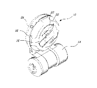
A light emitting device, method and lens, the device comprising an LED emitting a beam of light and a transparent light conditioning lens concentric with the beam of light and through which the beam of light travels. The lens comprises a light concentrating part and a light diffusing part. The concentrating part concentrates a first portion of the light to form a first beam of light having a narrow angle of dispersion, preferably of less than about 10 degrees and the light diffusing part diffuses a second portion of the light to form a second beam of light concentric with the first beam and having a wide angle of dispersion greater than the narrow angle of dispersion, preferably greater than about 70 degrees. An intensity of the first beam is greater than an intensity of the second beam.


French Abstract

Un dispositif lumineux, des méthodes et une lentille, le dispositif comprenant une DEL émettant un faisceau de lumière et une lentille de conditionnement de lumière transparente concentrique avec le faisceau de lumière et à travers duquel le faisceau de lumière voyage. La lentille comprend une partie de concentration de la lumière et une partie de diffusion de la lumière. La partie de concentration concentre une première partie de la lumière pour former un premier faisceau de lumière avec un angle de dispersion étroit, de préférence inférieur à environ 10 °, et la partie de diffusion de lumière diffuse une seconde partie de la lumière pour former un second faisceau de lumière concentrique avec le premier faisceau et avec un grand angle de dispersion supérieur à langle étroit de dispersion, de préférence supérieur à environ 70 °. Une intensité du premier faisceau est supérieure à une intensité du second faisceau.

Claims

Note: Claims are shown in the official language in which they were submitted.


7
What is claimed is:
1. A light emitting device comprising:
an LED emitting a beam of light; and
a transparent light conditioning lens concentric with said beam of light
and through which said beam of light travels, said lens comprising
a light concentrating part and a light diffusing part;
wherein said concentrating part concentrates a first portion of said light
to form a first beam of light having a narrow angle of dispersion and said
light diffusing part diffuses a second portion of said light to form a
second beam of light concentric with said first beam and having a wide
angle of dispersion greater than said narrow angle of dispersion and
further wherein an intensity of said first beam is greater than an intensity
of said second beam.
2. The light emitting device of Claim 1, wherein said light
conditioning lens is a batwing style lends.
3. The light emitting device of Claim 1, wherein said narrow angle of
dispersion is less than about 10 degrees.
4. The light emitting device of Claim 1, wherein said wide angle of
dispersion is greater than about 70 degrees.
5. The light emitting device of Claim 1, further comprising a rotary
switch rotatable about an axis concentric with said beam of light and wherein
one of a plurality of different modes of operation can be selected by rotating
said rotary switch.
6. The light emitting device of Claim 1, wherein said transparent light
conditioning lens comprises a plurality of horizontal striations on an outer
surface thereof.

8
7. The light emitting device of Claim 1, wherein said transparent light
conditioning lens comprises a plurality of vertical striations on an outer
surface
thereof.
8. The light emitting device of Claim 1, further comprising a convex
lens cover covering said lens, said lens cover comprising a light intensifying
annular shoulder around a periphery thereof.
9. A method of providing illumination comprising:
providing an LED emitting light;
concentrating a first portion of said light to form a first beam of light
having a narrow angle of dispersion; and
diffusing a second portion of said light to form a second beam of light
concentric with said first beam and having a wide angle of
dispersion of greater than said narrow angle of dispersion;
wherein an intensity of said first beam is greater than an intensity of said
second beam.
10. The illumination method of Claim 9, wherein said light
conditioning lens is a batwing style lends.
11. The illumination method of Claim 9, wherein said narrow angle of
dispersion is less than about 10 degrees.
12. The illumination method of Claim 9, wherein said wide angle of
dispersion is greater than about 70 degrees.
13. The illumination method of Claim 9, further comprising providing a
rotary switch rotatable about an axis concentric with said beam of light and
selecting one of a plurality of different modes of operation by rotating said
rotary switch about said axis.

Description

Note: Descriptions are shown in the official language in which they were submitted.


CA 02703383 2010-05-07
1
TITLE OF THE INVENTION
LIGHT EMITTING DEVICE
FIELD OF THE INVENTION
[0001] The present invention relates to a light emitting device. In
particular, the
present invention relates to an assembly for conditioning light emitted from a
light source in order to provide both a strong spot beam light and a diffuse
light
from the light source.
BACKGROUND OF THE INVENTION
[0002] The prior art reveals a number of signalling devices that emit either a
concentrated spot beam of light, for example a conventional flashlight or the
like, or a diffuse light, for example a reading light or the like.
[0003] In environments containing smoke or of high turbidity, much of the
light
from sources having a wide beam is reflected back towards the source
whereas a strong beam penetrates the turbidity while producing some ambient
glow through reflection off the particles. This acts well as a beacon as well
as
providing better penetration of vision into the turbid medium than would
otherwise be possible with a wide beam. On the other hand, in smoke free
conditions or conditions of low turbidity, a concentrated beam is poorly
visible
from the sides.
[0004] What is needed for use in all such situations, therefore, is a light
emitting
device that simultaneously emits a wide angle beam visible from the sides and
a concentrated beam.
SUMMARY OF THE INVENTION

CA 02703383 2010-05-07
2
[0005] In order to address the above and other drawbacks there is disclosed a
light emitting device comprising an LED emitting a beam of light and a
transparent light conditioning lens concentric with the beam of light and
through
which the beam of light travels. The lens comprises a light concentrating part
and a light diffusing part. The concentrating part concentrates a first
portion of
the light to form a first beam of light having a narrow angle of dispersion,
preferably of less than about 10 degrees and the light diffusing part diffuses
a
second portion of the light to form a second beam of light concentric with the
first beam and having a wide angle of dispersion greater than the narrow angle
of dispersion, preferably greater than about 70 degrees. An intensity of the
first
beam is greater than an intensity of the second beam.
[0006] Additionally, there is also disclosed a method of providing
illumination
comprising providing an LED emitting light, concentrating a first portion of
the
light to form a first beam of light having a narrow angle of dispersion of
preferably less than about 10 degrees, and diffusing a second portion of the
light to form a second beam of light concentric with the first beam and having
a
wide angle of dispersion greater than the narrow angle of dispersion and
preferably of greater than about 70 degrees. An intensity of the first beam is
greater than an intensity of the second beam.
[0007] Other objects, advantages and features of the present invention will
become more apparent upon reading of the following non-restrictive description
of specific embodiments thereof, given by way of example only with reference
to the accompanying drawings.
BRIEF DESCRIPTION OF THE DRAWINGS
[0008] In the appended drawings:
[0009] Figure 1 provides a left raised perspective view of a light emitting
device
in accordance with an illustrative embodiment of the present invention;

CA 02703383 2010-05-07
3
[0010] Figure 2 provides a top plan view a light emitting device in accordance
with an illustrative embodiment of the present invention;
[0011] Figure 3A provides a cutaway view along I11-III of the light emitting
device in Figure 2;
[0012] Figure 3B provides a side plan view of a batwing type lens including
horizontal striations in accordance with an illustrative embodiment of the
present invention;
[0013] Figure 3C provides a side plan view of a batwing type lens including
vertical striations in accordance with an illustrative embodiment of the
present
invention;
[0014] Figure 4A is a polar plot of the intensity of a conventional high power
LED;
[0015] Figure 4B is a polar plot of the intensity of a conventional high power
LED combined with a collimating lens assembly; and
[0016] Figure 4C is a polar plot of the intensity of a conventional high power
LED combined with a collimating and dispersing lens assembly in accordance
with an illustrative embodiment of the present invention.
DESCRIPTION OF ILLUSTRATIVE EMBODIMENTS
[0017] The present invention is illustrated in further details by the
following non-
limiting examples.
[0018] Referring now to Figures 1 and 2, and in accordance with an
illustrative
embodiment of the present invention, a light emitting device, generally
referred

CA 02703383 2010-05-07
4
to using the reference numeral 10, will now be described. The device 10
comprises a light source 12 such as an LED under control of electronics (not
shown) powered by a battery held in a battery compartment 14. A bezel
mounted rotary switch 16 is provided to allow the requisite selective input
control to the electronics, for example to select one of plurality of
different
signalling signatures, such as steady on, intermittent flashing or the
maritime
distress signal SOS. The LED 12 illustratively is supported on a reflective
surface 18. A collimating/dispersing transparent light conditioning lens 20
manufactured from transparent glass, acrylic, polycarbonate or the like is
secured to the reflective surface 18 immediately above the LED 12.
Additionally, a lens cover 22 manufactured from transparent polycarbonate or
the like serves the dual purpose of protecting the LED 12 and lens 20 from the
outside elements as well as securing the rotary switch 16 to the body 24 of
the
device 10.
[0019] Referring now to Figure 3A, the lens 20 is of a Batwing style or the
like
known in the art and used on many conventional LED flashlights. The lens 20 is
adapted to fit directly over the LED 12, which is illustratively a low profile
surface mounted device with a generally flat emitting surface. Typically the
peripheral edges 26 of such a lens are silvered such that substantially all
the
light emitted by the LED 12 is efficiently propagated forward and exits the
lens
20 in a direction concentric with the LED. However, in an illustrative
embodiment of the present invention the silvering is absent thus allowing a
portion of the light emitted by the LED to escape via the sides of the lens
20.
[0020] Referring now to Figure 4A, prior art LEDs typically emit relatively
constant light with an angle of dispersion 28 of about 60 about a central
axis of
the LED. The prior art also discloses the use of a silvered Batwing type lens
or
the like to collimate the light such that the angle of dispersion 28 is of
about 10
about a central axis of the LED.
[0021] Referring back to Figure 3A together with Figure 4C, in operation, the

CA 02703383 2010-05-07
LED 12 emits light a first portion of which is collimated by the lens 20 to
form a
relatively intense spot beam of concentrated light 30 having an angle of
dispersion of about 100 about a central axis of the LED and a second portion
of
which is dispersed by the lens 20 to form a less intense diffuse ambient light
32
5 having an angle of dispersion of about 70 about a central axis of the LED
and
concentric with the beam of concentrated light 30. Additionally, the
relatively
thick annular shoulder section 34 about a periphery of the transparent lens
cover 22 serves to intensify light propagating through it, thereby producing a
distinguishable ring signature of somewhat more intense light around the base
of the lens cover 22.
[0022] Still referring to Figure 3A and Figure 4C, a person of skill in the
art will
understand that the light dispersion resulting from the combination of the
lens
and the LED 12 can be modified through variation of the shape of the lens
15 20. Indeed, known batwing type lenses, for example, come in a variety of
forms
offering varying focus, such that a spot beam 30 having a different angle of
dispersion can be achieved through appropriate selection of the lens 20. In
this
regard, an elongate batwing style lens will typically produce more focus and
less dispersion while a wider batwing style lens will typically produce more
20 dispersion and less focus. Additionally, the dispersion of the light can be
affected according to the positioning of the LED 12 relative to the lens 20.
For
example, positioning the LED 12 farther within the lens cavity 36 would
typically
lead to a higher percentage of the available light being dispersed, and vice-
versa.
[0023] Referring to Figure 3B and Figure 3C, in a particular embodiment the
outer surface of the lens 20 can be machined, moulded or otherwise formed to
include a plurality of respectively horizontal striations 38 (that is,
oriented
perpendicular to a central axis of the lens 20) or vertical striations 40
(that is,
oriented in-line with a central axis of the lens 20). The striations can be
either
grooves or raised ridges. The striations 38, 40 aid in light dispersion by
introducing surfaces which modify the path followed by light emitted by the
LED

CA 02703383 2010-05-07
6
12.
[0024] Although the present invention has been described hereinabove by way
of specific embodiments thereof, it can be modified, without departing from
the
spirit and nature of the subject invention as defined in the appended claims.

Representative Drawing
A single figure which represents the drawing illustrating the invention.
Administrative Status

2024-08-01:As part of the Next Generation Patents (NGP) transition, the Canadian Patents Database (CPD) now contains a more detailed Event History, which replicates the Event Log of our new back-office solution.

Please note that "Inactive:" events refers to events no longer in use in our new back-office solution.

For a clearer understanding of the status of the application/patent presented on this page, the site Disclaimer , as well as the definitions for Patent , Event History , Maintenance Fee  and Payment History  should be consulted.

Event History

Description Date
Maintenance Fee Payment Determined Compliant 2022-05-10
Inactive: Late MF processed 2022-05-10
Inactive: COVID 19 - Deadline extended 2020-05-14
Inactive: COVID 19 - Deadline extended 2020-04-28
Common Representative Appointed 2019-10-30
Appointment of Agent Request 2018-09-14
Revocation of Agent Request 2018-09-14
Inactive: Agents merged 2018-09-01
Inactive: Agents merged 2018-08-30
Grant by Issuance 2017-09-26
Inactive: Cover page published 2017-09-25
Inactive: IPC deactivated 2017-09-16
Pre-grant 2017-08-14
Inactive: Final fee received 2017-08-14
Notice of Allowance is Issued 2017-02-23
Letter Sent 2017-02-23
Notice of Allowance is Issued 2017-02-23
Inactive: Approved for allowance (AFA) 2017-02-16
Inactive: QS passed 2017-02-16
Letter Sent 2016-10-12
Amendment Received - Voluntary Amendment 2016-09-14
Inactive: IPC assigned 2016-08-30
Inactive: S.30(2) Rules - Examiner requisition 2016-03-23
Inactive: Report - No QC 2016-03-22
Inactive: IPC expired 2016-01-01
Letter Sent 2015-04-22
All Requirements for Examination Determined Compliant 2015-04-10
Request for Examination Requirements Determined Compliant 2015-04-10
Request for Examination Received 2015-04-10
Letter Sent 2014-04-30
Inactive: Single transfer 2014-04-08
Inactive: Cover page published 2010-11-07
Application Published (Open to Public Inspection) 2010-11-07
Inactive: IPC assigned 2010-10-12
Inactive: First IPC assigned 2010-10-12
Inactive: IPC assigned 2010-10-12
Inactive: IPC assigned 2010-10-08
Application Received - Regular National 2010-06-09
Inactive: Filing certificate - No RFE (English) 2010-06-09
Small Entity Declaration Determined Compliant 2010-05-07

Abandonment History

There is no abandonment history.

Maintenance Fee

The last payment was received on 2017-05-01

Note : If the full payment has not been received on or before the date indicated, a further fee may be required which may be one of the following

  • the reinstatement fee;
  • the late payment fee; or
  • additional fee to reverse deemed expiry.

Patent fees are adjusted on the 1st of January every year. The amounts above are the current amounts if received by December 31 of the current year.
Please refer to the CIPO Patent Fees web page to see all current fee amounts.

Fee History

Fee Type Anniversary Year Due Date Paid Date
Application fee - small 2010-05-07
MF (application, 2nd anniv.) - small 02 2012-05-07 2012-05-01
MF (application, 3rd anniv.) - small 03 2013-05-07 2013-05-01
Registration of a document 2014-04-08
MF (application, 4th anniv.) - small 04 2014-05-07 2014-05-01
MF (application, 5th anniv.) - small 05 2015-05-07 2015-03-19
Request for examination - small 2015-04-10
MF (application, 6th anniv.) - small 06 2016-05-09 2016-05-03
Registration of a document 2016-10-05
MF (application, 7th anniv.) - small 07 2017-05-08 2017-05-01
Final fee - small 2017-08-14
MF (patent, 8th anniv.) - small 2018-05-07 2018-05-03
MF (patent, 9th anniv.) - small 2019-05-07 2019-05-01
MF (patent, 10th anniv.) - small 2020-05-07 2020-05-22
MF (patent, 11th anniv.) - small 2021-05-07 2020-05-22
MF (patent, 12th anniv.) - small 2022-05-09 2022-05-10
Late fee (ss. 46(2) of the Act) 2022-05-10 2022-05-10
MF (patent, 13th anniv.) - small 2023-05-08 2023-05-08
MF (patent, 14th anniv.) - small 2024-05-07 2024-04-17
Owners on Record

Note: Records showing the ownership history in alphabetical order.

Current Owners on Record
9609385 CANADA INC.
Past Owners on Record
TIMOTHY D.F. FORD
Past Owners that do not appear in the "Owners on Record" listing will appear in other documentation within the application.
Documents

To view selected files, please enter reCAPTCHA code :


To view images, click a link in the Document Description column. To download the documents, select one or more checkboxes in the first column and then click the "Download Selected in PDF format (Zip Archive)" or the "Download Selected as Single PDF" button.

List of published and non-published patent-specific documents on the CPD .

If you have any difficulty accessing content, you can call the Client Service Centre at 1-866-997-1936 or send them an e-mail at CIPO Client Service Centre.


Document
Description 
Date
(yyyy-mm-dd) 
Number of pages   Size of Image (KB) 
Claims 2010-05-06 3 93
Description 2010-05-06 6 218
Drawings 2010-05-06 4 111
Abstract 2010-05-06 1 20
Representative drawing 2010-10-12 1 15
Claims 2016-09-13 2 68
Representative drawing 2017-08-27 1 12
Maintenance fee payment 2024-04-16 2 59
Filing Certificate (English) 2010-06-08 1 167
Reminder of maintenance fee due 2012-01-09 1 113
Courtesy - Certificate of registration (related document(s)) 2014-04-29 1 103
Reminder - Request for Examination 2015-01-07 1 118
Acknowledgement of Request for Examination 2015-04-21 1 174
Commissioner's Notice - Application Found Allowable 2017-02-22 1 162
Courtesy - Acknowledgement of Payment of Maintenance Fee and Late Fee (Patent) 2022-05-09 1 431
Examiner Requisition 2016-03-22 3 219
Amendment / response to report 2016-09-13 5 137
Final fee 2017-08-13 1 46
Maintenance fee payment 2018-05-02 1 24
Maintenance fee payment 2019-04-30 1 24
Maintenance fee payment 2023-05-07 1 25