Note: Descriptions are shown in the official language in which they were submitted.
CA 02703594 2010-04-22
DESCRIPTION
CONTROL DEVICE
TECHNICAL FIELD
The present invention relates to a control device which is applied to
a system having an engine configured such that a compression ratio or
expansion ratio can be changed.
BACKGROUND ART
In a system using an engine (e.g. an automobile or the like), a state
determination, i.e. a diagnosis, of an exhaust system (an exhaust gas
sensor or an exhaust gas purification catalyst or the like) is performed by an
engine electronic control unit (hereinafter, referred to as "ECU"). This
on-board diagnosis (OBD) of the exhaust system includes a catalyst
temperature estimation, a catalyst malfunction diagnosis, an exhaust gas
sensor malfunction diagnosis, which are explained below, etc..
(1) For example, in this kind of the system, a catalyst is positioned
in an exhaust passage in order to purify an exhaust gas. Generally, the
catalyst has a property that a purification ratio is high only within a
prescribed temperature range (e.g. 400-800 C). Accordingly, various
proposals are conventionally made to increase the catalyst temperature
rapidly after an engine is started (for example, Unexamined Japanese
Patent Publication No. 2007-231820, etc.).
Further, this kind of the catalyst is deteriorated by deleterious
components (lead and sulfur, etc.) in fuel and heat. When the catalyst is
I
CA 02703594 2010-04-22
deteriorated, an exhaust gas purification ratio is decreased and an exhaust
emission is increased. Accordingly, various kinds of devices for
determining the deterioration of the catalyst are conventionally proposed (for
example, Unexamined Japanese Patent Publication Nos. 5-133264 and
2004-28029, etc.).
Meanwhile, so-called three-way catalyst is widely used as this kind
of the catalyst. The three-way catalyst has a function called as an oxygen
adsorption function or an oxygen storage function. The function is one
which reduces NOx (nitrogen oxide) in the exhaust gas and adsorbs (stores)
oxygen removed from the NOx therein when an air-fuel ratio of air-fuel
mixture is lean, while discharging the adsorbed oxygen for oxidizing
unburned components such as HC and CO, etc. in the exhaust gas when an
air-fuel ratio of air-fuel mixture is rich. Accordingly, as a maximum value
(hereinafter, referred to as "maximum oxygen storage amount") of an
amount (hereinafter, referred to as "oxygen storage amount") of the oxygen
which can be stored by the three-way catalyst is large, a purification ability
of the three-way catalyst is high. In other words, a deterioration state of
the three-way catalyst can be determined by the maximum oxygen storage
amount.
In a catalyst deterioration detection device disclosed in the
Unexamined Japanese Patent Publication No. 5-133264, a first air-fuel ratio
sensor is positioned upstream of the three-way catalyst positioned in the
exhaust passage. Further, a second air-fuel ratio sensor is positioned
downstream of the three-way catalyst positioned in the exhaust passage.
In this configuration, a deterioration determination of the three-way catalyst
(a calculation of the maximum oxygen storage amount) is performed as
2
CA 02703594 2010-04-22
follows. First, an air-fuel ratio of an air-fuel mixture supplied into a
cylinder
of an engine is set to a predetermined lean air-fuel ratio for a predetermined
time period. Thereby, the oxygen is stored in the three-way catalyst to an
upper limit of the adsorption ability thereof. Thereafter, the air-fuel ratio
of
the air-fuel mixture is forcibly changed to a predetermined rich air-fuel
ratio.
Then, the air-fuel ratio detected by the second air-fuel ratio sensor is
maintained to a stoichiometric air-fuel ratio for a constant time period At,
and thereafter is changed to a rich air-fuel ratio. On the basis of the
difference A(A/F) between the stoichiometric air-fuel ratio and the rich
air-fuel ratio, At, and an intake air amount, the maximum oxygen storage
amount is calculated.
However, the maximum oxygen storage amount changes depending
on a temperature of the three-way catalyst. Specifically, when the
temperature of the three-way catalyst increases, the maximum oxygen
storage amount increases. Therefore, the catalyst deterioration
determination which is performed on the basis of the maximum oxygen
storage amount calculated without considering the catalyst temperature has
a problem that the determination accuracy is not adequate. Accordingly, a
catalyst deterioration detection device disclosed in the Unexamined
Japanese Patent Publication No. 2004-28029 is configured to correct the
maximum oxygen storage amount based on the catalyst temperature at the
period of calculating the maximum oxygen storage amount.
As explained above, the catalyst temperature is an important
parameter for the on-board diagnosis of the warm-up state and the
deterioration state, etc. of the catalyst. The catalyst temperature can be
measured by a catalyst bed temperature sensor (for example, see the
3
CA 02703594 2010-04-22
Unexamined Japanese Patent Publication No. 2005-69218, etc.).
Alternatively, the catalyst temperature can be estimated on board by using
other engine parameters such as intake air flow rate, etc. (for example, see
the Unexamined Japanese Patent Publication Nos. 2004-28029 and
2004-197716, etc.). In terms of responsiveness, accuracy, cost, etc., it is
preferred that the catalyst temperature is estimated on board, rather than
measured by a sensor.
(2) For example, in order to control an air-fuel ratio of an engine, a
so-called air-fuel ratio feedback control is normally performed. The control
is performed on the basis of an output of an exhaust gas sensor (an air-fuel
ratio sensor) positioned in an exhaust passage. The exhaust gas sensor is
generally an oxygen sensor for generating an output corresponding to an
oxygen concentration in an exhaust gas. The exhaust gas sensor(s) is/are
provided upstream and/or downstream of a catalyst for purifying the exhaust
gas in the flowing direction of the exhaust gas.
The exhaust gas sensor provided downstream of the catalyst is
normally comprises a solid-electrolyte type oxygen sensor which has an
output property that an output is generally constant under a rich air-fuel
ratio
relative to the stoichiometric air-fuel ratio and under a lean air-fuel ratio
relative to the stoichiometric air-fuel ratio and rapidly changes around the
stoichiometric air-fuel ratio. The exhaust gas sensor provided upstream of
the catalyst is normally comprises the above-mentioned solid-electrolyte
type oxygen sensor or a limiting-current type oxygen concentration sensor
which has a relatively linear output property within wide range of the air-
fuel
ratio.
When a malfunction occurs in the above-mentioned exhaust gas
4
CA 02703594 2010-04-22
sensor, an air-fuel ratio control of the engine may not be appropriately
performed. Accordingly, a device for performing a malfunction diagnosis of
the exhaust gas sensor is conventionally proposed (for example, see the
Unexamined Japanese Patent Publication Nos. 2003-254135, 2004-225684,
2007-16712, etc.).
This kind of the device is configured to determine if the exhaust gas
sensor is normal on the basis of the response state of the exhaust gas
sensor to the air-fuel ratio change of air-fuel mixture. For example, in a
device disclosed in the Unexamined Japanese Patent Publication No.
2004-225684, the air-fuel ratio is forced to be alternatively changed between
predetermined rich and lean air-fuel ratios, and it is determined if there is
a
sensor malfunction on the basis that whether a sensor output correctly
follows the air-fuel ratio change.
DISCLOSURE OF THE INVENTION
An engine configured such that a compression ratio or expansion
ratio can be varied, is known (for example, see the Unexamined Japanese
Patent Publication Nos. 2003-206771, 2004-156541, 2004-169660,
2007-303423, 2008-19799, 2008-157128, etc.). It should be noted that the
"compression ratio" used herein includes "mechanical compression ratio"
and "actual compression ratio".
The mechanical compression ratio is a value obtained by dividing
the sum of a clearance volume (a combustion chamber volume at a piston
top dead center) and a piston displacement volume by the clearance volume,
and is referred to as nominal compression ratio or geometric compression
ratio. For example, the mechanical compression ratio can be changed by
CA 02703594 2010-04-22
relatively moving a crank case on which a crank shaft is rotatably supported
and a cylinder block on which upper end portion a cylinder head is secured,
along a central axis of the cylinder. Alternatively, in the case that a
connection rod (a member for connecting a piston and the above-mentioned
crank shaft to each other) is configured to be folded, the mechanical
compression ratio can be changed by changing the folded state of the
connection rod.
The actual compression ratio is an effective compression ratio
relative to an intake air, and is typically a value obtained by dividing a
combustion chamber volume at the beginning of the compression of the
intake air by the combustion chamber volume at the end of the compression.
The actual compression ratio can be changed along with the
above-explained change of the mechanical compression ratio. Further, the
actual compression ratio can be changed by changing the mechanical
compression ratio and operation timing of an intake valve and/or an exhaust
valve, or by changing the operation timing of the intake valve and/or the
exhaust valve in place of changing the mechanical compression ratio.
The expansion ratio is a ratio between the volume at the end of the
expansion in the expansion stroke and the volume (= the clearance volume)
at the beginning of the expansion in the expansion stroke. When the
mechanical compression ratio or the actual compression ratio is changed,
the expansion ratio can be changed. That is, the expansion ratio can be
changed by changing the mechanical compression ratio and/or the opening
and/or closing timing of the exhaust valve. Further, the mechanical
compression ratio, the actual compression ratio and the expansion ratio can
be independently set and changed by changing the opening and/or closing
6
CA 02703594 2010-04-22
timing of the intake and/or exhaust valve (for example, see the Unexamined
Japanese Patent Publication Nos. 2007-303423, 2008-19799, 2008-157128,
etc.).
In this kind of the engine, when the compression ratio or the
expansion ratio is changed, the combustion state of the air-fuel mixture
and/or the exhaust gas temperature are/is changed. Accordingly, the
change of the compression ratio or the expansion ratio exerts the accuracy
of the on-board diagnosis of the exhaust system.
The object of the present invention is to improve the accuracy of the
on-board diagnosis in a system having an engine wherein a compression
ratio or an expansion ratio can be changed.
(A) A control device of a first aspect of the present invention is
applied to a system having an engine configured such that a compression
ratio or an expansion ratio can be changed. For example, in the system,
the engine, a passage for an exhaust gas discharged from the engine, and a
member (a catalyst, an exhaust gas sensor, etc.) positioned in the passage
may be included.
The feature of the first aspect of the present invention is that the
control device comprises: a compression ratio acquisition part or an
expansion ratio acquisition part, and a temperature estimation part. It
should be noted that the "part" can be referred to as "means" (for example,
"compression ratio acquisition means", etc.: hereinafter, the same applies).
The compression ratio acquisition part is configured to acquire the
compression ratio (the term "acquisition" includes detection or estimation.
hereinafter, the same applies.). The expansion ratio acquisition part is
configured to acquire the expansion ratio.
7
CA 02703594 2010-04-22
The temperature estimation part is configured to estimate a
temperature of the exhaust gas or the member on the basis of the acquired
compression ratio or expansion ratio.
Specifically, for example, the temperature estimation part may be
configured to estimate the temperature of the catalyst on the basis of the
compression ratio acquired by the compression ratio acquisition part. In
this case, the temperature estimation part may be configured to estimate the
temperature of the catalyst on the basis of, at least, a parameter relating to
the intake air amount in the engine, and the compression ratio acquired by
the compression ratio acquisition part. As the parameters, for example, an
intake air flow rate, a load ratio, a throttle valve opening degree,
acceleration operation amount, etc. may be used.
The above-mentioned system may be further comprised of a
determination part. The determination part is configured to determine the
state of the above-mentioned member based on the result of the estimation
of the temperature by the temperature estimation part. For example, the
deterioration determination part as the determination part determines the
deterioration state of the catalyst on the basis of the catalyst temperature
estimated by the temperature estimation part.
In the control device of the present invention having the
above-explained configuration, an estimated temperature of the exhaust gas
or the above-mentioned member is acquired on the basis of the acquired
compression ratio or the acquired expansion ratio. For example, the
estimated temperature may be acquired by the acquired compression ratio
and a calculated temperature obtained based on the parameter(s) in
consideration of a reference predetermined compression ratio (maximum or
8
CA 02703594 2010-04-22
minimum compression ratio). Alternatively, the estimated temperature may
be acquired by correcting the calculated temperature obtained on the basis
of the parameter(s) depending on the compression or expansion ratio.
Further, an on-board diagnosis of the above-mentioned member may be
performed by using the estimated temperature acquired as explained above.
Therefore, according to the present invention, the accuracy of the
on-board diagnosis can be improved in the system having an engine that a
compression ratio or an expansion ratio can be changed.
The determination part may be configured to determine the state of
the above-mentioned member when the compression or expansion ratio is
constant or the change thereof is within a predetermined range.
According to the above-explained configuration, the determination of
the state of the above-mentioned member is performed when the
compression or expansion ratio is constant or the change thereof is within
the predetermined range. Thereby, the determination of the state of the
above-mentioned member is accurately performed.
. Further, the above-mentioned system may be further comprised of a
compression ratio control part or an expansion ratio control part. The
compression ratio control part is configured to control the compression ratio
(depending on an operating condition of the engine). Similarly, the
expansion ratio control part is configured to control the expansion ratio
(depending on the operating condition of the engine). In this case, the
compression ratio control part or the expansion ratio control part may be
configured to control the compression or expansion ratio, respectively to a
constant ratio upon the determination of the above-mentioned state
performed by the determination part.
9
CA 02703594 2010-04-22
According to the above-explained configuration, the compression
ratio control part controls the compression ratio to a constant compression
ratio upon the determination of the state of the above-mentioned member.
Similarly, the expansion ratio control part controls the expansion ratio to a
constant expansion ratio upon the determination of the state of the
above-mentioned member. Further, the determination part determines the
state of the above-mentioned member in the condition that the compression
or expansion ratio is constant or the change thereof is within the
predetermined range.
Specifically, for example, the compression ratio control part variably
controls the compression ratio depending on the operating condition of the
engine when the deterioration determination of the catalyst is not performed,
while forbidding the change of the compression ratio upon the deterioration
determination of the catalyst. Upon the deterioration determination of the
catalyst, the estimated temperature of the catalyst is acquired on the basis
of the compression ratio which is controlled to a constant compression ratio
by the compression ratio control part. On the basis of the estimated
temperature, the deterioration state of the catalyst is determined by the
deterioration determination part.
According to the above-explained configuration, the change of the
temperature of the above-mentioned member is restricted as possible during
the determination of the state of the member. Therefore, the determination
of the state of the member is accurately performed.
For example, the compression ratio control part may be configured
to control the compression ratio to a low constant compression ratio in order
to increase the temperature of the catalyst upon the determination of the
CA 02703594 2010-04-22
deterioration state of the catalyst by the deterioration determination part
when the estimated temperature is lower than a predetermined lower limit
temperature for the deterioration determination. Alternatively, the
compression ratio control part may be configured to control the compression
ratio to a high constant compression ratio in order to decrease the
temperature of the catalyst upon the determination of the deterioration state
of the catalyst by the deterioration determination part when the estimated
temperature is higher than a predetermined upper limit temperature for the
deterioration determination.
According to the above-explained configuration, upon the
determination of the deterioration state of the catalyst by the deterioration
determination part, the temperature of the catalyst may be forced to be set
within a range suitable for the deterioration determination. Therefore,
according to this configuration, the determination of the deterioration state
of
the catalyst can be accurately performed.
(B) A control device of a second aspect of the present invention is
applied to a system having an engine configured such that a compression
ratio or an expansion ratio can be changed. For example, in the system,
the engine, a passage for an exhaust gas discharged from the engine, and a
member (a catalyst, an exhaust gas sensor, etc.) positioned in the passage
may be included.
The exhaust gas sensor is configured to generate an output
corresponding to a concentration of a specific component (for example,
oxygen concentration) in the exhaust gas (the exhaust gas sensor may be
referred to as "air-fuel ratio sensor" since it generates an output
corresponding to an air-fuel ratio of an air-fuel mixture). The exhaust gas
11
CA 02703594 2010-04-22
sensor may be provided upstream and/or downstream of an exhaust gas
purification catalyst positioned in the passage in the exhaust gas flowing
direction.
The control device comprises a compression ratio control part or an
expansion ratio control part. The compression ratio control part is
configured to control a compression ratio of the engine (depending on an
operating condition of the engine). Similarly, the expansion ratio control
part is configured to control an expansion ratio of the engine (depending on
the operating condition of the engine).
The feature of the second aspect of the present invention is that the
compression or expansion ratio control part controls the compression or
expansion ratio to a constant ratio during a diagnosis of a malfunction of the
above-mentioned member.
In the control device of the present invention having the
above-explained configuration, the compression or expansion ratio is
controlled such that it is constant during the diagnosis of the malfunction of
the above-mentioned member (for example, during the diagnosis of the
malfunction of the exhaust gas sensor based on the output of the exhaust
gas sensor). Thereby, the combustion state of the air-fuel mixture is
controlled constant as possible during the diagnosis of the malfunction of
the above-mentioned member. Therefore, according to the present
invention, the diagnosis of the malfunction of the member can be accurately
performed.
(C) A control device of a third aspect of the present invention is
applied to a system having an engine wherein a compression ratio can be
changed.
12
CA 02703594 2010-04-22
The control device comprises a compression ratio acquisition part, a
determination part, and a determination permission part. The compression
ratio acquisition part is configured to acquire the compression ratio. The
determination part is configured to determine a state of a member
positioned in a passage for an exhaust gas discharged from the engine.
The determination permission part is configured to permit the determination
part to perform the determination on the basis of the compression ratio
acquired by the compression ration acquisition part.
It should be noted that the control device may further comprise a
compression ratio control part. The compression ratio control part may be
configured to control the compression ratio to a constant ratio upon the
determination of the above-mentioned state by the determination part (In
this case, the compression ratio acquisition part and/or the expansion ratio
acquisition part may be omitted).
According to the above-explained configuration, for example, the
determination is performed by the determination part when the compression
ratio is constant or the change thereof is within a predetermined range.
Thereby, the change of the combustion state of the air-fuel mixture or the
change of the exhaust gas temperature may be restricted as possible during
the determination of the state of the above-mentioned member.
Accordingly, the determination (deterioration determination, etc.) of the
state
of the above-mentioned member can be accurately performed.
(D) A control device of a fourth aspect of the present invention is
applied to a system having an engine wherein an expansion ratio can be
changed.
The control device comprises an expansion ratio acquisition part, a
13
CA 02703594 2010-04-22
determination part, and a determination permission part. The expansion
ratio acquisition part is configured to acquire the expansion ratio. The
determination part is configured to determine a state of a member
positioned in a passage for an exhaust gas discharged from the engine.
The determination permission part is configured to permit the determination
part to perform determination on the basis of the expansion ratio acquired
by the expansion ratio acquisition part.
It should be noted that the control device may further comprise an
expansion ratio control part. The expansion ratio control part may be
configured to control the expansion ratio to a constant ratio upon the
determination of the above-mentioned state by the determination part (In
this case, the expansion ratio acquisition part and/or the determination
permission part may be omitted).
According to the above-explained configuration, for example, the
determination is performed by the determination part when the expansion
ratio is constant or the change thereof is within a predetermined range.
Thereby, the change of the combustion state of the air-fuel mixture or the
change of the exhaust gas temperature can be restricted as possible during
the determination of the state of the above-mentioned member.
Accordingly, the determination (the deterioration determination, etc.) of the
state of the member can be accurately performed.
BRIEF DESCRIPTION OF THE DRAWINGS
Fig. 1 is a schematic view showing an entire configuration of a
system S (a vehicle, etc.) to which the present invention is applied,
including
an inline multi-cylinder engine and a control device of an embodiment of the
14
CA 02703594 2010-04-22
present invention.
Fig. 2A is a graph showing an output property of an upstream
air-fuel ratio sensor shown in Fig. 1.
Fig. 2B is a graph showing an output property of a downstream
air-fuel ratio sensor shown in Fig. 1.
Fig. 3 is a flowchart showing an operation of a catalyst OBD
condition determination in a first concrete example of an operation of the
control device of the embodiment shown in Fig. 1.
Fig. 4 is a flowchart showing a mechanical compression ratio
set/control operation in the first concrete example.
Fig. 5 is a flowchart showing a catalyst OBD operation in the first
concrete example.
Fig. 6 is a graph showing an aspect of the performance of the
catalyst OBD shown in Fig. 5.
Fig. 7 is a flowchart showing an operation of an estimated catalyst
temperature acquisition in the first concrete example of the operation of the
control device of the embodiment shown in Fig. 1.
Fig. 8 is a flowchart showing an operation of a sensor OBD condition
determination in a second concrete example of the operation of the control
device of the embodiment shown in Fig. 1.
Fig. 9 is a flowchart showing a sensor OBD operation in the second
concrete example.
Fig. 10 is a flowchart showing a control operation of compression
and expansion ratios in a third concrete example of the operation of the
control device of the embodiment shown in Fig. 1.
Fig. 11 is a flowchart showing a catalyst OBD operation in the third
CA 02703594 2010-04-22
concrete example.
Fig. 12 is a flowchart showing a catalyst OBD operation in a fourth
concrete example of the operation of the control device of the embodiment
shown in Fig. 1.
Fig. 13 is a flowchart showing a catalyst OBD operation in a fifth
concrete example of the operation of the control device of the embodiment
shown in Fig. 1.
BEST MODE FOR CARRYING OUT THE INVENTION
Below, an embodiment of the present invention (an embodiment
which the applicant deems best at the filing of this application) will be
explained by referring to the drawings.
It should be noted that the following description relating to the
embodiment only concretely describes just an example which embodies the
present invention to the extent possible in order to satisfy description
requirements (statement requirement, enablement requirements) for the
specification required by the law. Accordingly, as explained later, it is
quite
natural that the present invention is not limited to the illustrative
embodiment
explained below. Modifications of the embodiment will be explained
together at the end of this explanation, since it may lead to a difficulty to
understand the self-consistent explanation of the embodiment if
explanations of the modifications are inserted into the explanation of the
embodiment.
<Entire Configuration of System>
Fig. 1 is a schematic view showing an entire configuration of a
system S (a vehicle, etc.) to which the present invention applies, including
16
CA 02703594 2010-04-22
an inline multi-cylinder engine 1 and a control device of an embodiment of
the present invention. It should be noted that a sectional side view of the
engine 1 which is cut on a face orthogonal to the cylinder array direction, is
shown in Fig. 1.
In this embodiment, the engine 1 is configured such that a
mechanical compression ratio can be changed within a predetermined range
(for example, between 9 and 26). Further, the engine 1 is configured such
that the mechanical compression ratio, an actual compression ratio and an
expansion ratio can be set and changed in a substantially independent way
by changing the mechanical compression ratio and intake and exhaust valve
timings.
The control device 2 of this embodiment is configured to control an
operation of the engine 1 and to determine (diagnose) a state of each part of
the system S to accordingly indicate the result of the determination
(diagnosis) to a driver.
The engine 1 of this embodiment has a cylinder block 11, a cylinder
head 12, a crank case 13 and a variable compression ratio mechanism 14.
Further, an intake passage 15 and an exhaust passage 16 are connected to
the engine 1.
<<Cylinder Block>>
Cylinder bores 111 which are generally cylindrical through holes, are
formed in the cylinder block 11. As explained above, a plurality of cylinder
bores 111 are arranged in line along the cylinder array direction in the
cylinder block 11. A piston 112 is housed inside each cylinder bore 111
such that it can reciprocally move along a central axis (hereinafter, referred
to as "cylinder central axis CCA") of the cylinder bore 111.
17
CA 02703594 2010-04-22
<<Cylinder Head>>
The cylinder head 12 is connected to an upper end portion of the
cylinder block 11 (an end portion of the cylinder block 11 at the top dead
center side of the piston 112). The cylinder head 12 is secured to the
upper end portion of the cylinder block 11 by bolts not shown, etc. such that
the cylinder head does not move relative to the cylinder block 11.
A plurality of recesses are provided on a lower end portion of the
cylinder head 12 at positions corresponding to an upper end portion of each
cylinder bore 111. That is, in the condition that the cylinder head 12 is
connected and secured to the cylinder block 11, combustion chambers CC
are formed by spaces inside of the cylinder bores 111 at an upper side (the
near side to the cylinder head 12) from the upper faces of the pistons 112
and spaces inside (at lower side) of the above-mentioned recesses. Intake
ports 121 and exhaust ports 122 are formed in the cylinder head 12 such
that the intake and exhaust ports communicate with the combustion
chambers CC.
Further, intake valves 123, exhaust valves 124, a variable intake
valve timing device 125, a variable exhaust valve timing device 126 and
injectors 127 are provided in the cylinder head 12.
The intake valves 123 are those for controlling states of the
communication between the intake ports 121 and the combustion chambers
CC. The exhaust valves 124 are those for controlling states of the
communication between the exhaust ports 122 and the combustion
chambers CC.
The variable intake and exhaust valve timing devices 125 and 126
are configured to be able to change an actual compression ratio and an
18
CA 02703594 2010-04-22
expansion ratio by changing opening and closing timings of the intake and
exhaust valves 123 and 124. Since the illustrative embodiment of the
variable intake and exhaust valve timing devices 125 and 126 are well
known, the explanations thereof are omitted.
The injectors 127 are configured to be able to inject into the intake
ports 121 fuel to be supplied into the combustion chambers CC.
<<Crank Case>>
A crank shaft 131 is positioned parallel to the cylinder array direction
and is rotatably supported in the crank case 13. The crank shaft 131 is
connected to the pistons 112 via connection rods 132 such that it is rotated
by the reciprocal movement of the pistons 112 along the cylinder central
axis CCA.
<<Variable Compression Ratio Mechanism>>
The variable compression ratio mechanism 14 of this embodiment is
configured to be able to change the mechanical compression ratio within the
above-mentioned range by moving the combination of the cylinder block 11
and the cylinder head 12 relative to the crank case 13 along the cylinder
central axis CCA to change the clearance volume. The variable
compression ratio mechanism 14 has the similar configuration to that
described in the Unexamined Japanese Patent Publication Nos.
2003-206771, 2007-056837, etc. Accordingly, in this specification, the
detailed explanation of the mechanism is omitted and only the summary
thereof will be explained below.
The variable compression ratio mechanism 14 has a connection
mechanism 141 and a drive mechanism 142. The connection mechanism
141 is configured to connect the cylinder block 11 and the crank case 13 to
19
CA 02703594 2010-04-22
each other such that the cylinder block 11 and the crank case 13 can moves
relative to each other along the cylinder central axis CCA. The drive
mechanism 142 has a servomotor, a gear mechanism, etc., and is
configured to be able to move the cylinder block 11 and the crank case 13
relative to each other along the cylinder central axis CCA.
<<Intake and Exhaust Passages>>
An intake passage 15 including an intake manifold, a surge tank, etc.
is connected to the intake ports 121. A throttle valve 151 is positioned in
the intake passage 15. The throttle valve 151 is configured to be rotated
by a throttle valve actuator 152 comprised of a DC motor.
On the other hand, an exhaust passage 16 including an exhaust
manifold is connected to the exhaust ports 122. The exhaust passage 16
is one for the exhaust gas discharged from the combustion chambers CC
via the exhaust ports 122. A catalytic converter 161 is positioned in the
exhaust passage 16. The catalytic converter 161 has a three-way catalyst
having an oxygen adsorption function therein and is configured to be able to
purify HC, CO and NOx in the exhaust gas.
<<Various Sensors>>
Various sensors such as a cooling water temperature sensor 171, a
crank position sensor 172, an intake cam position sensor 173, an exhaust
cam position sensor 174, an air flow meter 175, an intake air temperature
sensor 176, a throttle position sensor 177, an upstream air-fuel ratio sensor
178a, a downstream air-fuel ratio sensor 178b, an accelerator opening
degree sensor 179, etc. are provided in the system S.
The cooling water temperature sensor 171 is mounted on the
cylinder block 11. The cooling water temperature sensor 171 is configured
CA 02703594 2010-04-22
to output a signal corresponding to a temperature (a cooling water
temperature Tw) of a cooling water in the cylinder block 11.
The crack position sensor 172 is mounted on the crank case 13.
The crank position sensor 172 is configured to output a waveform signal
having a pulse depending on a rotation angle of the crank shaft 131.
Specifically, the crank position sensor 172 is configured to output a signal
having a narrow pulse every the crank shaft 131 rotates by 10 degrees and
a wide pulse every the crank shaft 131 rotates 360 degrees. That is, the
crank position sensor 172 is configured to output a signal corresponding to
an engine speed Ne.
The intake and exhaust cam position sensors 173 and 174 are
mounted on the cylinder head 12. The intake cam position sensor 173 is
configured to output a waveform signal having a pulse depending on a
rotation angle of an intake cam shaft not shown (which is included in the
variable intake valve timing device 125) for reciprocally moving the intake
valves 123. Similarly, the exhaust cam position sensor 174 is configured to
output a waveform signal having a pulse depending on a rotation angle of an
exhaust cam shaft not shown.
The air flow meter 175, the intake air temperature sensor 176 and
the throttle position sensor 177 are mounted on the intake passage 15.
The air flow meter 175 is configured to output a signal corresponding to a
mass flow rate (an intake air flow rate Ga) of an intake air flowing in the
intake passage 15. The intake air temperature sensor 176 is configured to
output a signal corresponding to a temperature of the intake air. The
throttle position sensor 177 is configured to output a signal corresponding to
a rotation phase (a throttle valve opening degree TA) of the throttle valve
21
CA 02703594 2010-04-22
151.
The upstream and downstream air-fuel ratio sensors 178a and 178b
are mounted on the exhaust passage 16. The upstream air-fuel ratio
sensor 178a is positioned upstream of the catalytic converter 161 in a
flowing direction of an exhaust gas. The downstream air-fuel ratio sensor
178b is positioned downstream of the catalytic converter 161 in the flowing
direction of the exhaust gas.
Fig. 2A is a graph showing an output property of the upstream
air-fuel ratio sensor 178a shown in Fig. 1. Fig. 2B is a graph showing an
output property of the downstream air-fuel ratio sensor 178b shown in Fig.
1.
As shown in Fig. 2A, the upstream air-fuel ratio sensor 178a is a
universal type air-fuel ratio sensor having an output property that an output
thereof is relatively linear within a wide range of the air-fuel ratio.
Specifically, the upstream air-fuel ratio sensor 178a is comprised of a
limiting current type oxygen concentration sensor. As shown in Fig. 2B,
the downstream air-fuel ratio sensor 178b is an air-fuel ratio sensor having
an output property that an output thereof is generally constant under the rich
side and the lean side of the stoichiometric air-fuel ratio while the output
rapidly changes around the stoichiometric air-fuel ratio. Specifically, the
downstream air-fuel ratio sensor 178b is comprised of a solid electrolyte
type zirconia oxygen sensor.
Referring to Fig. 1 again, the accelerator opening degree sensor 179
is configured to output a signal corresponding to an operation amount (an
accelerator operation amount Accp) of an acceleration pedal operated by
the driver. Further, an alarm device 182 having an alarm indicating light,
22
CA 02703594 2010-04-22
etc. is provided at a position which the driver can easily see.
<<Control Device>>
The control device 2 has a CPU 201, a ROM 202, a RAM 203, a
backup RAM 204, an interface 205 and a bus 206. The CPU 201, the
ROM 202, the RAM 203, the backup RAM 204 and the interface 205 are
connected to each other by the bus 206.
Routines (programs) to be performed by the CPU 201, tables
(lookup tables, maps), parameters, etc. are previously stored in the ROM
202. The RAM 203 is configured to be able to temporarily store data as
necessary when the CPU 201 performs the routines. The backup RAM
204 is configured such that data is stored therein when the CPU 201
performs the routines in the condition that a power is applied and the stored
data can be retained after the power shutdown.
The interface 205 is electrically connected to various sensors such
as the cooling water temperature sensor 171, the crank position sensor 172,
the intake cam position sensor 173, the exhaust cam position sensor 174,
the air flow meter 175, the intake air temperature sensor 176, the throttle
position sensor 177, the upstream air-fuel ratio sensor 178a, the
downstream air-fuel ratio sensor 178b, the accelerator opening degree
sensor 179, etc., and is configured to be able to transmit the signals from
the sensors to the CPU 201.
Further, the interface 205 is electrically connected to operating parts
such as the variable intake valve timing device 125, the variable exhaust
valve timing device 126, the injectors 127, the drive mechanism 142, the
alarm device 182, etc., and is configured to be able to transmit operating
signals for operating the operating parts from the CPU 201 to the operating
23
CA 02703594 2010-04-22
parts.
Furthermore, the interface 205 is configured to transmit an output
signal (on the basis thereof, a setting state of the mechanical compression
ratio in the engine 1 can be recognized) of an encoder provided in the
servomotor provided in the drive mechanism 142 to the CPU 201.
That is, the control device 2 is configured to receive signals from the
above-mentioned various sensors via the interface 205 and output the
above-mentioned operating signals to each operating part on the basis of
the result of the calculation performed by the CPU 201 depending on the
received signals.
It should be noted that in this embodiment, a compression ratio
control part, an expansion ratio control part, a compression ratio acquisition
part and an expansion ratio acquisition part of the present invention are
comprised of the drive mechanism 142 for setting a state of movement of
the cylinder block 11 and the cylinder head 12 relative to the crank case 13
by the variable compression ratio mechanism 14, the variable intake and
exhaust valve timing device 125 and 126 for setting intake and exhaust
valve timings, and the control device 2 (the CPU 201) for controlling the
states thereof.
Further, in this embodiment, a temperature estimation part and a
determination part (a diagnosis determination part) of the present invention
are comprised of the control device 2 (the CPU 201) and the
above-mentioned various sensors connected to the control device 2 via the
interface 205.
Furthermore, in this embodiment, a determination permission part of
the present invention is comprised of the control device 2 (the CPU 201).
24
CA 02703594 2010-04-22
<Summary of Operation>
Below, a summary of operation of the system S of this embodiment
will be explained.
<<Control of Air-fuel Ratio>>
A target air-fuel ratio is set on the basis of the throttle valve opening
degree TA, etc. The target air-fuel ratio is normally set to the
stoichiometric air-fuel ratio. On the other hand, in the case of acceleration,
etc., the target air-fuel ratio may be set to a ratio slightly shifted to a
rich or
lean side of the stoichiometric air-fuel ratio as necessary.
Further, when a predetermined sensor OBD condition is satisfied, a
malfunction diagnosis (a sensor OBD) of the upstream and/or downstream
air-fuel ratio sensor(s) 178a and/or 178b is performed once every one trip
(which is a period from the start of the engine 1 to the stop thereof).
During the sensor OBD, the target air-fuel ratio is controlled such that it is
changed in the rectangular waveform between a ratio shifted to a rich side
of the stoichiometric air-fuel ratio and a ratio shifted to a lean side of the
stoichiometric air-fuel ratio (a so-called air-fuel ratio active control).
Further, the above-mentioned air-fuel ratio active control is
performed when a deterioration diagnosis of the catalytic converter 161 (a
catalyst OBD) is performed in a predetermined operating condition during
the stationary operation.
A base value of an amount of a fuel injected from the injectors 127
(a base fuel injection amount) is acquired on the basis of the target air-fuel
ratio set as explained above, the intake air flow rate Ga, etc.
When a predetermined feedback control condition is not satisfied,
such as when the upstream and downstream air-fuel ratio sensors 178a and
CA 02703594 2010-04-22
178b are not sufficiently warmed immediately after the engine 1 is started,
an open-loop control is performed on the basis of the base fuel injection
amount. (In this open-loop control, a learning control may be performed on
the basis of learning correction coefficient.)
When the feedback control condition is satisfied, an actual amount
(a command fuel injection amount) of the fuel injected from the injectors 127
is acquired by performing a feedback correction of the base fuel injection
amount on the basis of the outputs of the upstream and downstream air-fuel
ratio sensors 178a and 178b. Further, an air-fuel ratio learning for
acquiring the learning correction coefficient for the above-mentioned
open-loop control is performed on the basis of the outputs of the upstream
and downstream air-fuel ratio sensors 178a and 178b.
<<Catalyst OBD>>
The air-fuel ratio of the air-fuel mixture is forced to be changed in the
rectangular waveform by the above-mentioned air-fuel ratio active control.
First, the air-fuel ratio of the air-fuel mixture is set to a predetermined
lean
air-fuel ratio for a predetermined period. Thereby, oxygen is stored in the
three-way catalyst of the catalytic converter 161 to the upper limit of the
adsorption ability. Thereafter, the air-fuel ratio of the air-fuel mixture is
forced to be changed to a predetermined rich air-fuel ratio. Then, the
air-fuel ratio detected by the downstream air-fuel ratio sensor 178b changes
to a rich side after it is maintained to the stoichiometric air-fuel ratio for
a
constant time At. A maximum oxygen storage amount of the three-way
catalyst of the catalytic converter 161 is calculated on the basis of the
difference A(A/F) between the stoichiometric air-fuel ratio and the rich
air-fuel ratio, At and the intake air amount at this time. The deterioration
26
CA 02703594 2010-04-22
diagnosis of the catalytic converter 161 is performed on the basis of the
acquired maximum oxygen storage amount.
<<Sensor OBD>>
The air-fuel ratio of the air-fuel mixture is forced to be changed in the
rectangular waveform by the above-mentioned air-fuel ratio active control.
At this time, it is determined if there is a malfunction of the upstream
and/or
downstream air-fuel ratio sensor(s) 178a and/or 178b by determining if an
output wave correctly following the change of the air-fuel ratio occurs.
Since a concrete content of such a sensor OBD is well known, the detailed
explanation thereof is omitted in this specification.
<<Control of Compression and Expansion Ratios>>
The mechanical compression ratio, the actual compression ratio and
the expansion ratio are controlled on the basis of the operating condition
such as the warmed condition, the load condition, etc. of the engine 1.
Specifically, the compression ratio is set to a low compression ratio
in order to promptly warm a body of the engine 1 and the catalytic converter
161 during a warming operation. When the operating condition of the
engine 1 reaches a regular area (at the running in the urban area, at the
running on the highway, etc.) after the engine has been warmed, the
compression ratio is set to a high compression ratio. Thereby, a heat
efficiency is increased and a fuel consumption is improved. On the other
hand, in a large output area (at rapid acceleration, at the running uphill,
etc.),
the compression ratio is set to a low compression ratio. Thereby, a
knocking is restricted while a large output is obtained.
The actual compression ratio is a value determined by an actual
stroke volume from when the compression action actually starts until the
27
CA 02703594 2010-04-22
piston 112 reaches a dead top center, and a clearance volume (a volume of
the combustion chamber CC at the dead top center of the piston 112). The
clearance volume is determined depending on the setting state of the
mechanical compression ratio. On the other hand, even when the piston
112 moves upwardly at the compression stroke, the compression action
does not substantially occur during the opening of the intake valve 123, and
the actual compression action starts from when the intake valve 123 is
closed. Accordingly, when the mechanical compression ratio is constant,
the actual compression ratio is decreased by delaying the closing timing of
the intake valve 123.
The expansion ratio is a ratio of a volume at the end of the
expansion at the expansion stroke to the clearance volume. As explained
above, the clearance volume is determined depending on the setting state of
the mechanical compression ratio. On the other hand, the expansion ratio
is variable depending on the opening timing of the exhaust valve 124. For
example, the exhaust gas temperature may be increased by advancing the
opening timing of the exhaust valve 124 in order to promptly warm the
catalytic converter 161. Further, an engine heat efficiency can be
increased by delaying the opening timing of the exhaust valve 124 as
possible.
Accordingly, for example, at the engine low load operation, the
engine heat efficiency can be increased by setting the expansion ratio to a
high ratio (for example, around 26) by setting the mechanical compression
ratio to a high ratio and delaying the opening timing of the exhaust valve
124 as possible, while an abnormal combustion such as knocking, etc. can
be restricted by setting the actual compression ratio to a low ratio (for
28
CA 02703594 2010-04-22
example, around 11) by delaying the closing timing of the intake valve 123
(a so-called high expansion ratio cycle).
Specifically, for example, as the engine load decreases, the
mechanical compression ratio and the expansion ratio are set to high ratios
while the closing timing of the intake valve 123 is delayed. Thereby, the
actual compression ratio is set to a generally constant ratio at the engine
low load or the engine high load.
In this regard, however, when the mechanical compression ratio and
the expansion ratio are changed during the OBD, the accuracy of the OBD
may be decreased. Specifically, when the mechanical compression ratio
and the expansion ratio are changed during the OBD, the combustion state
of the air-fuel mixture and/or the exhaust gas temperature change, and the
changes exert the outputs of the upstream and downstream air-fuel ratio
sensors 178a and 178b. Also, the change of the exhaust gas temperature
leads to a change of the temperature of the catalytic converter 161, and
then the oxygen adsorption function (an oxygen adsorption and discharge
property) of the catalytic converter 161 changes. In particular, in the OBD
of the downstream air-fuel ratio sensor 178b, when the oxygen adsorption
function of the catalytic converter 161 is not maintained constant, it is
difficult to perform the OBD accurately.
Accordingly, the variable compression ratio mechanism 14, the
variable intake valve timing device 125 and the variable exhaust valve
timing device 126 are controlled such that the mechanical compression ratio
and the expansion ratio are maintained (generally) constant during the OBD.
Alternatively, the OBD is permitted to be performed in the condition that the
mechanical compression ratio and the expansion ratio are maintained
29
CA 02703594 2010-04-22
(generally) constant.
<Explanation of Operation>
Next, a concrete example of the operation of the control device 2 of
this embodiment shown in Fig. 1 will be explained by using flowcharts. It
should be noted that in the following explanation, "step" is abbreviated as
"S" (in the drawings, "step" is also abbreviated as "S").
<First Concrete Example>
In a first concrete example as explained below, it is assumed that a
control of the mechanical compression ratio and the expansion ratio is
performed such that the mechanical compression ratio and the expansion
ratio are generally equal to each other. That is, in the first concrete
example, it is assumed that the opening timing of the exhaust valve 124 is
constant (is set to a maximally delayed timing within a variable range).
Further, it is assumed that the closing timing of the intake valve 123
is appropriately set depending on the operating condition. That is, in this
concrete example, it is assumed that the so-called high expansion ratio
cycle can be realized (the same applies to the other concrete examples).
<<Determination of Catalyst OBD Condition>>
The CPU 201 performs a catalyst OBD condition determination
routine 300 shown in Fig. 3 every a predetermined timing comes.
First, at S310, it is determined if a catalyst OBD condition is satisfied.
The catalyst OBD condition is that the engine 1 has been warmed (the
cooling water temperature Tw _> TWO), the amount of the change of the
throttle valve opening degree TA per unit time is smaller than or equal to a
predetermined amount, the vehicle speed is higher than or equal to a
predetermined speed, and the intake air flow rate is lower than or equal to a
CA 02703594 2010-04-22
predetermined flow rate (around an intake air flow rate wherein a so-called
"blow-by" does not occur in the catalytic converter 161).
When the catalyst OBD condition is satisfied (S310=Yes), the
process proceeds to S320, and it is determined if the satisfaction of the
catalyst OBD condition at this time is the first satisfaction after the engine
1
starts. When the satisfaction of the catalyst OBD condition at this time is
the first satisfaction after the engine 1 starts (S320=Yes), the process
proceeds to S330, and a catalyst OBD flag Xc is set. When the catalyst
OBD condition is not satisfied (S310=No) or when the satisfaction of the
catalyst OBD condition at this time is not the first satisfaction after the
engine 1 starts (S320=No), the process proceeds to S340, and the catalyst
OBD flag Xc is reset. Thereafter, this routine is terminated once.
<<Setting of Mechanical Compression Ratio (Expansion Ratio)>>
The CPU 201 performs a mechanical compression ratio setting
routine 400 shown in Fig. 4 every a predetermined timing comes. It should
be noted that in this concrete example, as explained above, the opening
timing of the exhaust valve 124 is constant. Accordingly, in this concrete
example, a compression ratio control part (a compression ratio control
means) and an expansion ratio control part (an expansion ratio control
means) of the present invention are realized by the process of this routine
400 in the control device 2 (the CPU 201).
First, at S410, it is determined if the engine 1 has been warmed (the
cooling water temperature Tw _> TWO). When the engine 1 is being
warmed (S410=No), the process proceeds to S415. At S415, the
mechanical compression ratio F m (i.e. the expansion ratio E e) is set to a
low value E m0 (i.e. E e0) to facilitate the warming of the engine 1 and the
31
CA 02703594 2010-04-22
catalytic converter 161 by increasing the exhaust gas temperature.
When the engine 1 has been warmed (S410=Yes), the process
proceeds to S420, and it is determined if the catalyst OBD flag Xc is set.
When the catalyst OBD flag Xc is not set (S420=No), the present operating
condition is in a normal operating after the engine 1 has been warmed.
Accordingly, in this case, the process proceeds to S425. At S425, the
mechanical compression ratio E m is acquired by using a map, etc. on the
basis of the engine speed Ne and the load ratio KL. It should be noted that
the load ratio KL can be acquired on the basis of the intake air flow rate Ga
or the throttle valve opening degree TA or the accelerator operation amount
Accp as is well known.
When the engine 1 has been wormed (S410=Yes) and the catalyst
OBD flag Xc is set (S420=Yes), a catalyst OBD is performed. In this case,
first, the process proceeds to S430, and an estimated temperature of the
three-way catalyst (an estimated catalyst temperature Tc) in the catalytic
converter 161 is acquired. The acquisition of the estimated catalyst
temperature Tc (an on-board estimation of the catalyst temperature) will be
explained later in detail. Next, at S440, it is determined if the estimated
catalyst temperature Tc is lower than a predetermined lower limit
temperature TL. When the estimated catalyst temperature Tc is lower than
the lower limit temperature TL (S440=Yes), the process proceeds to S445,
and the mechanical compression ratio f m is set. When the estimated
catalyst temperature Tc is higher than or equal to the lower limit
temperature TL (S440=No), the process of S445 is skipped, and the process
proceeds to S450. At S450, it is determined if the estimated catalyst
temperature Tc is higher than a predetermined upper limit temperature TH.
32
CA 02703594 2010-04-22
When the estimated catalyst temperature Tc is higher than the upper limit
temperature TH (S450=Yes), the process proceeds to S455, and the
mechanical compression ratio E m is set. When the estimated catalyst
temperature Tc is lower than or equal to the upper limit temperature TH
(S450=No), the process of S455 is skipped.
At S445, the mechanical compression ratio is lowered by A E m from
the last time in order to increase the temperature of the catalytic converter
161 to a temperature range (TL - TH) suitable for the catalyst OBD by
increasing the exhaust gas temperature. By contrast, at S455, the
mechanical compression ratio is raised by A E m from the last time in order
to decrease the temperature of the catalytic converter 161 to a temperature
within the above-mentioned temperature range by decreasing the exhaust
gas temperature. On the other hand, when the estimated catalyst
temperature Tc is within the above-mentioned temperature range (S440=No,
S450=No), the processes of S445 and S455 are skipped, and therefore the
mechanical compression ratio is set to the same ratio as the last mechanical
compression ratio. That is, the mechanical compression ratio E m is
maintained constant.
After the above-explained process for setting the mechanical
compression ratio E m (the expansion ratio E e) is performed, the setting
state of the mechanical compression ratio E m is stored in the backup RAM
204 at S460. Thereafter, this routine is terminated once.
<<Catalyst OBD>>
The CPU 201 performs a catalyst OBD routine 500 shown in Fig. 5
every a predetermined timing comes. It should be noted that in this
concrete example, a determination part (determination means) and a
33
CA 02703594 2010-04-22
deterioration determination part (deterioration determination means) of the
present invention are realized by the process of this routine 500 in the
control device 2 (the CPU 201).
First, at S51 0, it is determined if the catalyst OBD flag Xc is set.
When the catalyst OBD flag Xc is set (S510=Yes), the process proceeds to
S520 and steps following it. When the catalyst OBD flag Xc is not set
(S510=No), the processes of S520 and the steps following it are skipped
and this routine is terminated once.
At S520, similar to S430, the estimated catalyst temperature Tc is
acquired. The acquisition of the estimated catalyst temperature Tc will be
explained later in detail. Next, at S530, it is determined if the estimated
catalyst temperature Tc is lower than the lower limit temperature TL. When
the estimated catalyst temperature Tc is higher than or equal to the lower
limit temperature TL (S530=No), the process proceeds to S540, and it is
determined if the estimated catalyst temperature Tc is higher than the upper
limit temperature TH. When the estimated catalyst temperature Tc is
within the above-mentioned temperature range (S530=No, S540=No), the
process proceeds to S550 and the catalyst OBD is performed and when it is
determined that a deterioration of the catalyst occurs, an alarm is generated
to the driver by the alarm device 182. After the catalyst OBD is performed,
the catalyst OBD flag is reset at S560.
When the estimated catalyst temperature Tc is not within the
above-mentioned temperature range (S530=Yes or S540=Yes), this routine
is terminated once. That is, the performance of the catalyst OBD is held
until the estimated catalyst temperature Tc reaches the above-mentioned
temperature range.
34
CA 02703594 2010-04-22
Fig. 6 is a graph showing an aspect when the catalyst OBD is
performed. In Fig. 6, (i) is a graph showing a change of the air-fuel ratio
during the catalyst OBD, (ii) is a graph showing an oxygen storage amount
OSA of the catalytic converter 161 which changes corresponding to the
change of the air-fuel ratio shown in (i), (iii) is a graph showing an output
Voxs of the downstream air-fuel ratio sensor 178b corresponding to the
change of the air-fuel ratio showin in (i) and the change of the oxygen
storage amount OSA shown in (ii).
First, as shown in (i) of Fig. 6, the air-fuel ratio is set to an air-fuel
ratio leaner than the stoichiometric air-fuel ratio (stoich) by AA/F from the
catalyst OBD starting time t1. Then, an exhaust gas having a lean air-fuel
ratio flows into the catalytic converter 161. Accordingly, as shown in (ii) of
Fig. 6, the oxygen storage amount OSA of the catalytic converter 161
progressively increases and reaches a peak value Cmax2 at the time t2.
When the oxygen storage amount OSA of the catalytic converter 161
reaches the peak value Cmax2, no oxygen can be adsorbed by the catalytic
converter 161 any more. Accordingly, from the time t2, the exhaust gas
including oxygen (the exhaust gas having a lean air-fuel ratio) starts to flow
out to the downstream side of the catalytic converter 161. Therefore, as
shown (iii) of Fig. 6, the output Voxs of the downstream air-fuel ratio sensor
178b changes to a value largely shifted to the lean side of the stoichiometric
air-fuel ratio.
When it is determined that the output Voxs of the downstream
air-fuel ratio sensor 178b changes to the value largely shifted to the lean
side of the stoichiometric air-fuel ratio at the time t2, the air-fuel ratio
is set
to an air-fuel ratio richer than the stoichiometric air-fuel ratio by AA/F as
CA 02703594 2010-04-22
shown in (i) of Fig. 6. Then, the exhaust gas having a rich air-fuel ratio
flows into the catalytic converter 161. At this time, the oxygen stored in the
catalytic converter 161 is consumed for an oxidization of inflow unburned
HC and CO. Accordingly, as shown in (ii) of Fig. 6, the oxygen storage
amount OSA of the catalytic converter 161 progressively decreases from
Cmax2, and the oxygen storage amount of the catalytic converter 161
becomes "zero" at the time t3.
When the oxygen storage amount OSA of the catalytic converter 161
becomes zero, no unburned HC nor CO can be oxidized by the catalytic
converter 161 any more. Accordingly, from the time 3, the gas having a
rich air-fuel ratio starts to flow out to the downstream side of the catalytic
converter 161. Therefore, as shown in (iii) of Fig. 6, the output Voxs of the
downstream air-fuel ratio sensor 178b changes from a value indicating a
lean air-fuel ratio to a value indicating a rich air-fuel ratio.
When it is determined that the output of the downstream air-fuel ratio
sensor 178b changes from the value indicating the lean air-fuel ratio to the
value indicating the rich air-fuel ratio at the time t3, the air-fuel ratio is
again
set to an air-fuel ratio leaner than the stoichiometric air-fuel ratio by LA/F
as
shown in (i) of Fig. 6. Thereby, as shown in (ii) of Fig. 6, the oxygen
storage amount OSA of the catalytic converter 161 continues to increase
from "zero" and reaches a peak value Cmax4 at the time t4. Then, similar
to the above explanation, at the time 4, the output Voxs of the downstream
air-fuel ratio sensor 178b changes from a value indicating a rich air-fuel
ratio
to a value indicating a lean air-fuel ratio. When it is determined that the
output Voxs of the downstream air-fuel ratio sensor 178b changes as
explained above at the time t4, the catalyst OBD is terminated and the
36
CA 02703594 2010-04-22
air-fuel ratio control is returned to the normal control.
By performing the rectangular waveform air-fuel ratio control (the
active control) as explained above, the maximum oxygen storage amount
Cmax of the catalytic converter 161 is acquired according to the following
expressions. It should be noted that in the following expressions, the value
"0.23" is a fraction of the oxygen included in the atmosphere by weight, and
mfr is a total amount of the fuel injection amounts Fi within a predetermined
period (a calculation cycle tsample).
A02=0.23 = mfr = AA/F
Cmax2= E A02 (zone t=t2 - t3)
Cmax4= E A02 (zone t=t3 - t4)
Cmax=(Cmax2+Cmax4)/2
As shown in the expressions, an amount of the shortage of the air in
the predetermined period tsample is calculated by multiplying the total
amount mfr of the fuel injection amounts in the predetermined period
tsample in the zone t=t2-t3 by the deviation AA/F of the air-fuel ratio A/F
compared with the stoichiometric air-fuel ratio, and the amount A02 of the
change of the oxygen storage amount (the amount of the consumption of
the adsorbed oxygen) in the predetermined period tsample is calculated by
multiplying the amount of the shortage of the air by the fraction of the
oxygen by weight. Then, the oxygen consumption amount until the
condition of the catalytic converter 161 changes from the condition that it
maximally stores oxygen therein to the condition that it maximally consumes
the oxygen, i.e. the peak value Cmax2, is estimated and calculated by
integrating the amount A02 of the change of the oxygen storage amount
from the time t2 to the time t3. Similarly, in the zone t=t3-t4, the oxygen
37
CA 02703594 2010-04-22
storage amount until the condition of the catalytic converter 161 changes
from the condition that it maximally consumes the oxygen to the condition
that it maximally stores oxygen therein, i.e. the peak value Cmax4, is
estimated and calculated by integrating the amount AO2 of the change of
the oxygen storage amount.
It should be noted that the above expressions can be simplified as
follows when the cylinder intake air amount Mc is constant (i.e. the intake
air
flow rate Ga is constant) during the catalyst OBD.
Cmax2=0.23 = mfr = AA/F = (t3-t2)
Cmax4=0.23 = mfr = AA/F = (t4-t3)
Cmax=(Cmax2+Cmax4)/2
It should be noted that in this concrete example, a determination
permission part (determination permission means) of the present invention
is realized by the processes of S440-S455 and S530-S540 in the control
device 2 (the CPU 201).
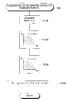
<<Acquisition of Estimated Catalyst Temperature>>
Next, a concrete example of the acquisition of the estimated
temperature Tc of the catalytic converter 161 will be explained. The CPU
201 performs an estimated catalyst temperature acquisition routine 700
shown in Fig. 7 every a predetermined timing comes.
First, at S710, the engine speed Ne, the load ratio KL and the
mechanical compression ratio f m are acquired. The mechanical
compression ratio f m can be easily and relatively correctly acquired by the
CPU 201 recognizing the condition of the operation control (for example, the
rotation angle of the motor) of the drive mechanism 142 performed by the
control device 2.
38
CA 02703594 2010-04-22
Next, at S720, a temperature Tc( E ml) is acquired on the basis of a
catalyst temperature map prepared using the engine speed Ne and the load
ratio KL as parameters in the condition that the mechanical compression
ratio E m is a predetermined value E ml (for example, a minimum value E
m_min) and the engine speed Ne and the load ratio KL acquired at S710.
Similarly, at S730, a temperature Tc(E m2) is acquired on the basis of a
catalyst temperature map prepared in the condition that the mechanical
compression ratio E m is a predetermined value E m2 (> E ml: for example,
a maximum value Em-max) and the engine speed Ne and the load ratio KL
acquired at S710.
Next, at S740, an estimated catalyst temperature Tc is acquired on
the basis of Tc( E ml), Tc(E m2), the mechanical compression ratio E m
acquired at S710 and a predetermined map or function. For example,
assuming that the change of the catalyst temperature occurred by the
change of the mechanical compression ratio E m in the case that the engine
speed Ne and the load ratio KL are constant is approximated by a straight
line, the estimated catalyst temperature Tc can be acquired as follows.
Tc=Tc(E m 1)+(E m- E ml) = (Tc( E m2)-Tc(E ml))/( E m2- E m 1l)
Thereafter, this routine is terminated once.
It should be noted that in this concrete example, a compression ratio
acquisition part (compression ratio acquisition means) and an expansion
ratio acquisition part (expansion ratio acquisition means) of the present
invention are realized by the process of S710 in the control device 2 (the
CPU 201). Further, a temperature estimation part (temperature estimation
means) of the present invention is realized by the processes of S720-S740
in the control device 2.
39
CA 02703594 2010-04-22
<<Action and Effect of First Concrete Example>>
= In this concrete example, the temperature of the catalytic converter
161 is estimated on-board on the basis of the actual compression ratio when
the catalyst OBD is performed. In other words, the estimated temperature
value of the catalytic converter 161 is corrected depending on the actual
compression ratio when the catalyst OBD is performed. Accordingly, the
estimation of the temperature of the catalytic converter 161 can be
accurately performed. Therefore, the catalyst OBD can be accurately
performed.
= In this concrete example, the mechanical compression ratio is
maintained constant by forbidding the change of the mechanical
compression ratio depending on the operating condition during the catalyst
OBD. Accordingly, the change of the temperature of the catalyst converter
161 is restricted as possible during the catalyst OBD. Therefore, the
catalyst OBD can be further accurately performed.
= In this concrete example, the mechanical compression ratio is
controlled to a constant value which is a low compression ratio in order to
increase the temperature of the catalytic converter 161 in the case that the
estimated catalyst temperature Tc is lower than a predetermined
deterioration determination lower limit temperature (TL). Further, the
mechanical compression ratio is controlled to a constant value which is a
high compression ratio in order to decrease the temperature of the catalytic
converter 161 in the case that the estimated catalyst temperature Tc is
higher than a predetermined deterioration determination upper limit
temperature (TH). Accordingly, upon the catalyst OBD, the temperature of
the catalytic converter 161 can be forced to be set within a range suitable
CA 02703594 2010-04-22
for the deterioration determination. Therefore, the catalyst OBD can be
appropriately performed.
<Second Concrete Example>
Similar to the above-explained first concrete example, in a second
concrete example explained below, it is assumed that the mechanical
compression ratio E m and the expansion ratio f e are controlled such that
the mechanical compression ratio E m and the expansion ratio F e are
generally equal to each other.
<<Determination of Sensor OBD Condition >>
The CPU 201 performs a sensor OBD condition determination
routine 800 shown in Fig. 8 every a predetermined timing comes. When
this routine is initiated, first, at S810, it is determined if a sensor OBD
has
not been completed at this trip. When the sensor OBD has not been
completed (S810=Yes), the process proceeds to S820, and it is determined
if a sensor OBD condition is satisfied.
The sensor OBD condition includes a condition that the accelerator
operation amount Accp is smaller than or equal to a predetermined amount
and the change of the mechanical compression ratio m is not necessary,
and a predetermined temperature condition. The temperature condition is
that (1) it is estimated that the upstream air-fuel ratio sensor 178a is
warmed to a predetermined activation temperature in the case of the OBD of
the upstream air-fuel ratio sensor 178a or that (2) the downstream air-fuel
ratio sensor 178b is warmed to a predetermined activation temperature and
the catalytic converter 161 is warmed to a predetermined activation
temperature to be a condition to be able to exert a predetermined oxygen
adsorption function in the case of the OBD of the downstream air-fuel ratio
41
CA 02703594 2010-04-22
sensor 178b. Their temperatures can be estimated by the CPU 201 using
engine parameters such as the cooling water temperature T2, etc.
When the sensor OBD condition is satisfied (S820=Yes), the
process proceeds to S830, and a sensor OBD flag Xd is set and this routine
is terminated once. On the other hand, when the sensor OBD condition is
not still satisfied (S820=No), the process proceeds to S840, and the sensor
OBD flag Xd is not set and this routine is terminated once. It should be
noted that after the sensor OBD is completed (S810=No), the process
proceeds to S840, and the sensor OBD flag Xd is reset, and this routine is
terminated once.
<<Setting of Mechanical Compression Ratio>>
The CPU 201 performs a mechanical compression ratio control
routine 900 shown in Fig. 9 every a predetermined timing comes. It should
be noted that in this concrete example, a compression ratio control part
(compression ratio control means) and an expansion ratio control part
(expansion ratio control means) of the present invention are realized by the
process of this routine 900 in the control device 2 (the CPU 201).
When this routine is initiated, first, at S910, it is determined if the
engine 1 has been warmed (if the cooling water temperature Tw > TWO).
When the engine 1 is being warmed (S910=No), the process
proceeds to S920. At S920, a target value of the mechanical compression
ratio f m is determined to a small value E m0 in order to facilitate the
warming of the engine 1, the catalytic converter 161, the upstream air-fuel
ratio sensor 178a and the downstream air-fuel ratio sensor 178b by
increasing the exhaust gas temperature.
When the engine 1 has been warmed (S910=Yes), the process
42
CA 02703594 2010-04-22
proceeds to S930, and it is determined if the sensor OBD flag Xd is set.
When the sensor OBD flag Xd is not set (S930=No), the present operating
condition is a normal operation after the engine 1 is warmed. Accordingly,
in this case, the process proceeds to S940. At S940, a target value of the
mechanical compression ratio E m is determined by using a map, etc. on
the basis of the engine speed Ne and the load ratio KL. It should be noted
that the load ratio KL can be acquired on the basis of engine parameters
such as the intake air flow rate Ga, the throttle valve opening degree TA, the
accelerator operation amount Accp, etc. as is well known.
After the target value of the mechanical compression ratio E m is
determined depending on the operating condition as explained above, the
process proceeds to S950, and the target value is stored in the backup RAM
204.
On the other hand, when the sensor OBD flag Xd is set (S930=Yes),
the target value of the mechanical compression ratio E m stored upon the
last initiation of this routine, is read. That is, the target value of the
mechanical compression ratio E m upon the initiation of this routine at this
time is set to the same ratio as that upon the last initiation of this
routine.
Thereby, the mechanical compression ratio E m is controlled constant
(the change of the mechanical compression ratio E m is forbidden) during
the sensor OBD.
After the target value of the mechanical compression ratio E m is
determined as explained above, the process proceeds to S970. At S970,
the drive mechanism 142 provided in the variable compression ratio
mechanism 14 is controlled such that the setting state of the mechanical
compression ratio E m corresponds to the above-mentioned target value,
43
CA 02703594 2010-04-22
and thereafter this routine is terminated once. In this regard, as explained
above, since the target value of the mechanical compression ratio E m is
the same as that upon the last initiation of this routine during the sensor
OBD, the setting state of the mechanical compression ratio Em during the
sensor OBD is maintained constant.
<Third Concrete Example>
In a third concrete example explained below, it is assumed that the
control of the mechanical compression ratio E m and the expansion ratio E
e is performed to be able to change the expansion ratio E e by controlling
the opening timing of the exhaust valve 124 even when the mechanical
compression ratio E m is constant.
<<Control of Compression Ratio and Expansion Ratio>>
The CPU 201 performs a compression ratio and expansion ratio
control routine 1000 shown in Fig. 10 every a predetermined timing comes.
It should be noted that in this concrete example, a compression ratio control
part (compression ratio control means) and an expansion ratio control part
(expansion ratio control means) of the present invention are realized by the
process of this routine 1000 in the control device 2 (CPU 201).
When this routine is initiated, first, at S1010, operating conditions
such as the engine speed Ne, the load ratio KL, etc. are acquired. Next, at
S1020, a target value of the actual compression ratio E r (a target actual
compression ratio E rt) is acquired on the basis of the operating conditions
and a map, etc. Following this, at S1030, a target value of the expansion
ratio E e (a target expansion ratio E et) is acquired on the basis of the
operating conditions and a map, etc.
Thereafter, at S1040, a target value of the mechanical compression
44
CA 02703594 2010-04-22
ratio E m (a target mechanical compression ratio E mt), an intake valve
closing timing IC and an exhaust valve opening timing EO are acquired for
accomplishing the target expansion ratio E et and the target actual
compression ratio E rt, and on the basis thereof, the drives of the variable
compression ratio mechanism 14, the variable intake valve timing device
124 and the variable exhaust valve timing device 126 are controlled (S1050),
and this routine is terminated once.
<<Catalyst OBD>>
The CPU 201 performs a catalyst OBD routine 1100 shown in Fig.
11 every a predetermined timing comes.
When this routine is initiated, first, at S1110, operating conditions
such as the engine speed Ne, the load ratio KL, etc. are acquired. Next, at
S1120, an expansion ratio E e is acquired. In this regard, in this example,
it is assumed that the expansion ratio E e is acquired on the basis of the
setting state of the mechanical compression ratio E m based on the output
signal of the encoder provided in the servomotor of the drive mechanism
142 of the variable compression ratio mechanism 14 and the exhaust valve
opening timing EO.
Next, at S1130, it is determined if the change of the expansion ratio
E e is within a predetermined range. In this regard, the amount of the
change of the expansion ratio E e can be acquired by temporally
statistically processing the value of the expansion ratio E e acquired at
S1120. Of course, the determination of S1130 can be simply performed by
determining if the deviation between the last value and the present value is
within a predetermined range.
When the change of the expansion ratio E e is not within the
CA 02703594 2010-04-22
predetermined range (S1130=No), the following processes are skipped, and
this routine is terminated once. When the change of the expansion ratio E
e is within the predetermined range (S1130=Yes), the process proceeds to
S1140, and it is determined if the other OBD conditions are satisfied.
When the OBD conditions including the condition relating to the
change of the expansion ratio E e are satisfied (S1140=Yes), the process
proceeds to 51150, and the estimated catalyst temperature Tc is acquired
on the basis of the expansion ratio E e. The acquisition of the estimated
catalyst temperature Tc is performed according to a method similar to the
estimated catalyst temperature acquisition routine 700 (see Fig. 7)
explained in connection with the above-explained first concrete example
(except that the expansion ratio E e is used in place of the mechanical
compression ratio E m in the above-explained routine 700, a process
generally similar to the routine 700 is performed). That is, the estimated
catalyst temperature Tc is corrected depending on the expansion ratio E e.
Thereafter, a catalyst OBD is performed (S1160) and this routine is
terminated once.
As explained above, in this concrete example, the catalyst OBD can
be accurately performed by employing the range of the change of the
expansion ratio F e as the condition for determining if the catalyst OBD
should be performed. Further, the accuracy of the estimation of the
estimated catalyst temperature Tc is improved by acquiring (correcting) the
estimated catalyst temperature Tc depending on the expansion ratio E e.
It should be noted that a determination part (determination means)
and a deterioration determination part (deterioration determination means)
of the present invention are realized by the process of this routine 1100 in
46
CA 02703594 2010-04-22
the control device 2 (the CPU 201) in this concrete example. Further, in
this concrete example, a determination permission part (determination
permission means) of the present invention is realized by the process of
S1130 performed by the control device 2 (the CPU 201).
<Fourth Concrete Example>
In a fourth concrete example explained below, similar to the
above-explained third concrete example, the mechanical compression ratio
F m and the expansion ratio E e are controlled by controlling the opening
timing of the exhaust valve 124 such that the expansion ratio F e can be
changed even when the mechanical compression ratio F m is constant.
<<Catalyst OBD>>
The CPU 201 performs a catalyst OBD routine 1200 shown in Fig.
12 every a predetermined timing comes.
When this routine is initiated, first, at S1210, operating conditions
such as the engine speed Ne, the load ratio KL, etc. are acquired. Next, at
S1220, an expansion ratio F e is acquired. Following this, at S1230, it is
determined if OBD conditions other than the condition relating to the
expansion ratio F e are satisfied. When the OBD conditions are not
satisfied (S1230=No), the following processes are skipped and this routine
is terminated once. When the OBD conditions other than the condition
relating to the expansion ratio F e are satisfied (S1230=Yes), the process
proceeds to S1240 and steps following it.
The range 0 F e of the change of the expansion ratio F e, for
making the range LTex of the change of the exhaust gas temperature a
predetermined small constant value which is allowed upon the performance
of the OBD, varies depending on the expansion ratio F e upon the
47
CA 02703594 2010-04-22
performance of the OBD (can be expressed as a function of the expansion
ratio E e). Accordingly, at S1240, a target value A E et of the range of the
change of the expansion ratio E e for being able to perform the OBD is
acquired on the basis of a map, etc. using the expansion ratio E e as a
parameter.
Next, the process proceeds to S1250, and the expansion ratio E e is
controlled such that the range A E e of the change of the actual expansion
ratio E e is limited to the target value A E et. Thereafter, the process
proceeds to S1260, and an estimated catalyst temperature Tc is acquired on
the basis of the expansion ratio E e. Next, a catalyst OBD is performed
(S1270) and this routine is terminated once.
As explained above, in this concrete example, the catalyst OBD can
be accurately performed by limiting the range of the change of the
expansion ratio E e upon the performance of the catalyst OBD. Further,
the accuracy of the estimation of the estimated catalyst temperature Tc is
improved by acquiring (correcting) the estimated catalyst temperature Tc
depending on the expansion ratio E e.
It should be noted that a determination part (determination means)
and a deterioration determination part (deterioration determination means)
of the present invention are realized by the process of this routine 1200 in
the control device 2 (the CPU 201) in this concrete example.
<Fifth Concrete Example>>
In a fifth concrete example explained below, similar to the
above-explained third and fourth concrete examples, it is assumed that the
mechanical compression ratio E m and the expansion ratio E e are
controlled such that the expansion ratio E e can be changed by controlling
48
CA 02703594 2010-04-22
the opening timing of the exhaust valve 124 even when the mechanical
compression ratio Em is constant.
<<Catalyst OBD>>
The CPU 201 performs a catalyst OBD routine 1300 shown in Fig.
13 every a predetermined timing comes.
When this routine is initiated, first, at S1310, operating conditions
such as the engine speed Ne, the load ratio KL, etc. are acquired. Next, at
S1320, it is determined if OBD conditions other than the condition relating to
the expansion ratio E e are satisfied. When the OBD conditions are not
satisfied (S1320=No), the following processes are skipped and this routine
is terminated once. When the OBD conditions other than the condition
relating to the expansion ratio E e are satisfied (S1320=Yes), the process
proceeds to S1330 and the steps following it.
At S1330, a target mechanical compression ratio E mt is set to a
predetermined value E mt_obd upon the OBD. The predetermined value
E mt_obd is set to a value (e.g. a low compression ratio of around 10) such
that the range LTex of the change of the exhaust gas temperature becomes
small compared with the change of the mechanical compression ratio E m
(i.e. the change of the expansion ratio E e). Next, the process proceeds to
S1340 and an intake valve closing timing IC such that the actual
compression ratio E r becomes a suitable value, is acquired on the basis of
a map, etc.
Next, the process proceeds to S1350 and the drives of the variable
compression ratio mechanism 14, the variable intake valve timing device
125 and the variable exhaust valve timing device 126 are controlled on the
basis of the result of the above-explained processes. At this time, the
49
CA 02703594 2010-04-22
throttle valve opening degree TA may be suitably adjusted such that the
required intake air amount is accomplished. Thereafter, a catalyst OBD is
performed (S1360) and this routine is terminated once.
As explained above, in this concrete example, the mechanical
compression ratio E m is set such that the catalyst OBD can be accurately
performed by limiting the range of the change of the expansion ratio E e
upon the performance of the catalyst OBD to a small range. Thereby, the
accuracy of the estimation of the estimated catalyst temperature Tc can be
improved, while the calculation load of the OBD can be decreased by
omitting the acquisition (the correction) of the estimated catalyst
temperature Tc depending on the expansion ratio E e.
It should be noted that a determination part (determination means)
and a deterioration determination part (deterioration determination means)
of the present invention are realized by the process of this routine 1300 in
the control device 2 (the CPU 201) in this concrete example. Further, a
compression ratio control part (compression ratio control means) and an
expansion ratio control part (expansion ratio control means) of the present
invention are realized by the process of S1330.
<Exemplification of Modifications>
It should be noted that the above-explained embodiments are just
examples of concrete configurations of the present invention which the
applicant considered best at the filing of this application as explained
above,
and therefore the invention should not be limited to the embodiments.
Accordingly, it is a matter of course that various modifications can be
applied to the concrete configurations indicated in the above-explained
embodiments without changing the essential parts of the present invention.
CA 02703594 2010-04-22
Below, several modified examples will be indicated. In this regard,
in the explanations of the following modified examples, the same names and
reference symbols as those of the above-explained embodiments are used
regarding the components of the modified examples having a configuration
or functions similar to those of the above-explained embodiments. Further,
regarding the explanations of the components, the explanations of the
above-explained embodiments can be suitably invoked as far as they are
inconsistent.
Of course, it is obvious that the modified examples are not limited to
the followings. It should not be permitted to narrowly construe the present
invention on the basis of the descriptions of the above-explained
embodiments and the following modified examples, since the benefit of the
applicant (in particular, who files an application early under the first file
system) is unduly prejudiced, while imitators unduly obtain benefits.
Further, it is obvious that the configuration of the above-explained
embodiments and the configuration described in connection with the
modified examples explained below can be suitably combined as far as it is
technically inconsistent.
(1) The present invention can be applied to a gasoline engine, a
diesel engine, a methanol engine, a bioethanol engine, and any other type
of engines. There is no specific limitation regarding the number of
cylinders, the type of the array of the cylinders (inline type, V type,
horizontal opposed type) and the type of the fuel injection (port injection
type, direct injection type).
(2) The configuration of the engine 1 including the variable
compression ratio mechanism 14 is not limited to those of the
51
CA 02703594 2010-04-22
above-explained embodiments. For example, the present invention can be
suitably applied to a case that the engine 1 is configured such that the
connection rod 132 has a multi-link structure and the mechanical
compression ratio is changed by changing a folded state of the connection
rod 132 (see the Unexamined Japanese Patent Publication No.
2004-156541, etc.).
(3) The control of the compression ratio of the above-explained first
and second concrete examples is mainly to control the mechanical
compression. However, the present invention is not limited thereto. For
example, the present invention may be similarly applied to a control of the
actual compression ratio by the variable intake and/or exhaust valve timing
device(s) 125 or 126. Further, the change of the actual compression ratio
depending on the operating condition can be performed by using both of the
change of the mechanical compression ratio performed by the variable
compression ratio mechanism 14 and the change of the valve timing
performed by the variable intake and/or exhaust valve timing device(s) 125
or 126. The present invention can be suitably applied to these cases.
That is, the compression ratio control of the above-explained first
and second concrete examples can be called as an expansion ratio control.
(4) The present invention is not limited to the concrete processes
described in connection with the above-explained concrete examples. For
example, the modifications explained below are possible.
The compression ratio and/or expansion ratio acquisition part(s) of
the present invention is/are not limited to the means disclosed in the
above-explained embodiments.
Specifically, in the above-explained embodiments, the setting state
52
CA 02703594 2010-04-22
of the mechanical compression ratio E m is acquired on the basis of the
output of the encoder provided in the servomotor of the drive mechanism
142 of the variable compression ratio mechanism 14. Of course, in place
of this, for example, the setting state of the mechanical compression ratio
E m can be acquired on the basis of an output of a linear sensor such as a
stroke sensor, etc. for generating an output depending on a relative position
between the cylinder block 11 and the cylinder head 12.
Further, the actual compression ratio E r and the expansion ratio E
e can be acquired on the basis of the setting state of the mechanical
compression ratio E m and the outputs of the intake and exhaust cam
position sensors 173 and 174.
In the above-explained embodiments, the catalyst OBD is performed
once per trip (period from the start of the operation of the engine to the
stop
thereof). However, the present invention is not limited to this.
Further, in the above-explained embodiments, the value of the
estimated catalyst temperature is used in the compression ratio control and
the catalyst deterioration determination. However, the present invention is
not limited to this. For example, the estimation of the warmed state of the
catalyst can be performed by estimating the catalyst temperature. That is,
the estimation of the warmed state of the catalyst may be included in the
catalyst OBD. Besides, the present invention is not limited to the concrete
examples explained in connection with the flowcharts in the above-explained
embodiments. For example, the estimation of the catalyst temperature can
be performed by various methods other than an interpolation or
extrapolation using a map of a temperature corresponding to two
compression ratios as in the above-explained embodiments. For example,
53
CA 02703594 2010-04-22
temperature maps corresponding to several standard compression ratios
are prepared and the estimation of the catalyst temperature may be
performed by selecting the temperature map corresponding to the standard
compression ratio which is closest to the actual compression ratio upon the
performance of the catalyst OBD.
For example, the sensor OBD can be performed by a method other
than the confirmation of the responsiveness upon the air-fuel ratio active
control.
In the case that OBD is simultaneously performed regarding both of
the upstream and downstream air-fuel ratio sensors 178a and 178b, as in
the above-explained concrete examples, it is sufficient that a single sensor
OBD flag Xd is prepared. Compared with this, in the case that after the
OBD is performed and completed regarding one of the sensors in which the
OBD condition is easily satisfied (for example, the upstream air-fuel ratio
sensor 178a), the OBD is performed regarding the other (for example, the
downstream air-fuel ratio sensor 178b), a flag Xd1 for the upstream air-fuel
ratio sensor and a flag Xd2 for the downstream air-fuel ratio sensor may be
separately prepared as flags for determining the satisfaction of the sensor
OBD condition in place of the above-mentioned sensor OBD flag Xd.
The compression ratio control is not limited to that of the
above-explained concrete example. For example, the setting of the
compression ratio to a low compression ratio E m0 during the warming of
the engine 1 can be omitted. That is, S910 and S920 can be omitted.
The OBD condition relating to the expansion ratio E e can be a
condition that "the expansion ratio e is generally constant" by narrowing
the predetermined range of S1130 to around the amount of the change of
54
CA 02703594 2010-04-22
the expansion ratio f e which occurs when the expansion ratio e is to be
controlled constant.
Further, the present invention can be applied to processes other
than the estimation of the catalyst temperature, the catalyst OBD and the
sensor OBD. For example, the present invention can be applied to the
temperature estimation and the OBD of members other than those (the
catalytic converter 161, the upstream air-fuel ratio sensor 178a and the
downstream air-fuel ratio sensor 178b) employed in the above-explained
concrete examples among the members positioned in the exhaust passage
16. Further, the present invention can be applied to a device for estimating
the exhaust gas temperature (see the Unexamined Japanese Patent
Publication Nos. 2000-227364, 2006-291828, etc.).
(5) Besides, it is a matter of course that modified examples which
are not particularly referred, are within the technical scope of the present
invention as far as the essential parts of the present invention are not
changed.
Further, the contents (including the specifications and the drawings)
of the Publications referred in this specification can be incorporated to
constitute a part of this specification.
Further, operationally or functionally expressed elements in the
elements constituting means of the present invention for solving the
problems include any structures which can accomplish the action and the
function other than the concrete structures disclosed in the above-explained
embodiments and the modified examples.