Language selection

Search

Patent 2703677 Summary

Third-party information liability

Some of the information on this Web page has been provided by external sources. The Government of Canada is not responsible for the accuracy, reliability or currency of the information supplied by external sources. Users wishing to rely upon this information should consult directly with the source of the information. Content provided by external sources is not subject to official languages, privacy and accessibility requirements.

Claims and Abstract availability

Any discrepancies in the text and image of the Claims and Abstract are due to differing posting times. Text of the Claims and Abstract are posted:

  • At the time the application is open to public inspection;
  • At the time of issue of the patent (grant).
(12) Patent Application: (11) CA 2703677
(54) English Title: MAGNETIC FLUX INTERRUPTION ELECTRICAL GENERATOR
(54) French Title: GROUPE ELECTROGENE A INTERRUPTION DE FLUX MAGNETIQUE
Status: Deemed Abandoned and Beyond the Period of Reinstatement - Pending Response to Notice of Disregarded Communication
Bibliographic Data
Abstracts

English Abstract


The invention provides an improved electrical generator. The improvement
relates to the
assembling of the inductor and inductive windings both on the stator one after
another
and no winding on the rotor, wherein rotor comprises a non ferromagnetic main
shaft
with ferromagnetic segments on its outer surface as magnetic flux interruption
elements,
wherein each assembly of an inductor and an inductive winding and the magnetic
flux
interruption element construct an electrical generator cell, wherein by
connecting the
conductor windings to a DC current a magnetic flux circuit is generated in the
above
mentioned cells, wherein by turning the rotor the generated magnetic flux is
interrupted
and thus an electrical current is induced in the inductive windings.


Claims

Note: Claims are shown in the official language in which they were submitted.

Claims
1.The concept of the magnetic flux interruption electrical generator and the
method of
generating electricity by interrupting the magnetic flux is shown in Fig.
1A/B, wherein the
simplified electrical generator unit comprising a ferromagnetic core(101), an
inductor
winding(103), two inductive windings(104) and (105), and a magnetic flux
interruption
element(102), wherein the magnetic flux interruption element(102) is moveable
from
position "a" to position "b" and vice versa, wherein by connecting the
inductor winding
(103) to a DC current, a magnetic field is generated in the inductor
winding(103),
wherein by means of movement of the magnetic flux interruption element(102)
from
position "a" to position "b" and vice versa, the generated magnetic flux(106)
and(107) in
the inductive windings(104) and (105) are interrupted periodically, wherein
the inductive
windings(104) and (105) are charged and thus an electrical current is induced
in the
inductive windings(104)and (105).
2. According to claim 1, the magnetic flux interruption electrical generator
comprises the
main components as shown in Fig. 2 A/B, a common ferromagnetic stator cylinder
(201), and a rotor (200) having the magnetic flux interruption elements (202)
on its outer
4

surface. In the ferromagnetic stator cylinder (201) the cogs are winded,
wherein every
other winding is a conductor with a conductive coil in between. The rotor
(200)
comprises a non ferromagnetic main shaft (204) and a non ferromagnetic
material (203)
as holder of the magnetic flux interruption elements that are fixed on its
outer surface.
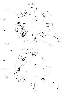
3. According to claim 2, the assembled magnetic flux interruption electrical
generator is
shown in Fig. 3A/B, wherein the conductor windings are connected to a DC
current,
whereby the every other magnetic pol is opposite (S or N), as shown in figure
3A the
magnetic flux circuit (308) is closed from pols "S" to "N" between the
inductor coil
(305) and the inductive coil(306) through the magnetic flux interruption
element(302),
wherein the inductive coil (306) is charged and thus the electrical current is
induced in
the inductive coil (306). By turning the rotor clockwise, from position "a" to
position "b"
as shown in Figure 3B, the magnetic flux interruption element(302) moves and
interrupts the magnetic flux(308) and closes the magnetic flux circuit(309)
between
the inductive coil (306) and the inductor coil(307), wherein the inductive
coil(306) will
be charged again and thus the electrical current is induced in the inductive
winding
(307) but the induced current in position "b" is in the opposite direction of
the induced
current in position "a", wherein the Alternative Current(AC) is induced in all
the
inductive windings.
4. According to claim 2, the assembled magnetic flux interruption electrical
generator is
shown In Fig. 4A/B, wherein the conductor windings are connected to a DC
current,
whereby all the magnetic pols are the same(S or N), as shown in Fig. 4A the
magnetic flux circuit(408) is closed from pols "S" to "N" between the inductor
winding
(405) and the inductive winding(406) through the magnetic flux interruption
element
(402), wherein the inductive winding(406) is charged and thus the electrical
current is
induced in the inductive winding(406). By turning the rotor clockwise from
position "a"
to position "b" as shown in Fig. 4B, the magnetic flux interruption
element(402) moves
to interrupt the magnetic flux(408) and closes the magnetic flux circuit(409)
between
the inductive winding(406) and the inductor winding(407), wherein the
inductive
5

winding(406) will be charged again and thus the electrical current is induced
in the
inductive winding(406) but in this arrangement the induced current in position
"b" is in
the same direction as the induced current in position "a", wherein the Direct
Current(DC)
is induced in all the inductive windings.
Drawings
Figure 1A
Figure 1B
Figure 2A
Figure 2B
Figure 3A
Figure 3B
Figure 4A
Figure 4B
6

Description

Note: Descriptions are shown in the official language in which they were submitted.


CA 02703677 2010-06-08
Magnetic Flux Interruption Electrical Generator
The invention provides an improved electrical generator. The improved
electrical generator is
more simplified and requires less maintenance because of having no windings
and related
components on the rotor.
Summery Of The Invention
The magnetic flux interruption electrical generator, comprising a common
ferromagnetic
stator with inner cogs, wherein the cogs are winded, wherein every other
winding is a
conductor with a conductive winding in between, a rotor with a non
ferromagnetic shaft
and ferromagnetic segments on its outer surface as magnetic flux interruption
elements,
wherein by connecting the conductor windings to a DC current any combination
of a
stator cog with a conductor winding, an adjacent stator cog with a conductive
winding
and a magnetic flux interruption elements can close a magnetic flux circuit,
wherein by
I

CA 02703677 2010-06-08
turning the rotor, the magnetic flux circuit will be interrupted in each
conductive winding,
wherein the conductive windings are charged and thus an electrical current is
induced in
the inductive windings.
Brief Description Of The Drawings
Fig. 1A and1 B show a conceptual demonstration of the magnetic flux
interruption
electrical generator, comprising a ferromagnetic core, one inductor winding,
two
inductive windings and one moveable magnetic flux interruption element and the
method of generating electricity.
Fig. 2A shows the stator with inductor and inductive windings
Fig. 2B shows the rotor with a non ferromagnetic shaft and the ferromagnetic
interruption elements on its outer surface.
Fig. 3A and 3B show the assembled AC electrical generator and the generated
magnetic fluxes by turning the rotor clockwise.
Fig. 4A and 4B shows the assembled DC electrical generator and the generated
magnetic fluxes by turning rotor clockwise.
Description
The invention provides a magnetic flux interruption electrical generator and a
method of
generating electricity. The method of generating electricity according to the
invention
which is shown in Fig.1 A and Fig. 1 B, comprising the ferromagnetic core(l
01), the
magnetic flux interruption element(102), the inductor winding(103), the
inductive
windings(104) and(105), wherein the magnetic flux interruption element(102) is
moveable from position "a" to position "b" and vice versa, wherein by
connecting the
2

CA 02703677 2010-06-08
inductor coil(103) to a DC current, a magnetic field is generated in the
inductor winding
(103), wherein by means of movement of the magnetic flux interruption
element(102)
from position "a" to position "b" and vice versa, the induced magnetic
fluxes(106) and
(107) in inductive windings are interrupted periodically, wherein the
inductive windings
are charged and thus the electrical current is induced in the inductive
windings.
According to the invention, the magnetic flux interruption electrical
generator comprises
the main components as shown in Fig. 2A and Fig. 2B, being a common
ferromagnetic
stator cylinder(201) having cogs protruding of out its inner surface, and a
rotor(200)
having the magnetic flux interruption elements(202) on its outer surface. In
the
ferromagnetic stator cylinder(201) the cogs have windings, wherein every other
winding
is a conductor with a conductive winding in between. The rotor(200) comprises
a non
ferromagnetic main shaft(204), a non ferromagnetic material (203) as holder of
the
magnetic flux interruption elements that are fixed on its outer surface.
The assembled magnetic flux interruption electrical generator is shown in Fig.
3A/B and
Fig. 4A/B, wherein the conductor windings are connected to a DC current,
whereby the
magnetic fields are generated in the inductors.
In Fig. 3A/B the conductor windings are connected to a DC current, whereby
every
other magnetic pol is opposite(S or N), as shown in Fig. 3A the magnetic flux
circuit
(308) is closed from pols "S" to "N" between the inductor winding(305) and the
inductive
winding(306) through the magnetic flux interruption element(302), wherein the
inductive
winding(306) is charged and thus the electrical current is induced in the
inductive
winding(306).
By turning the rotor clockwise from position "a" to position "b" as shown in
Fig. 3B, the
magnetic flux interruption element(302) moves and interrupts the magnetic
flux(308)
and closes the magnetic flux circuit(309) between inductive winding(306) and
inductor
winding(307), wherein the inductive winding(306) will be charged again and
thus the
electrical current is induced in the inductive winding(306) but the current
induced in
position "b" is in opposite direction of the current induced in position "a",
wherein the
Alternative Current(AC) is induced in all inductive windings.
In Fig. 4A/B the conductor windings are connected to a DC current, whereby all
the
3

CA 02703677 2010-06-08
magnetic pols are the same(S or N), as shown in Fig. 4A the magnetic flux
circuit(408)
is closed from pols "S" to "N" between the inductor winding(405) and the
inductive
winding(406) through the magnetic flux interruption element(402), wherein the
inductive
winding(406) is charged and thus the electrical current is induced in the
inductive
winding(406). By turning the rotor clockwise from position "a" to position "b"
as shown in
Fig. 4B, the magnetic flux interruption element(402) moves and interrupts the
magnetic
flux(408) and closes the magnetic flux circuit(409) between inductive
winding(406) and
inductor winding (407), wherein the inductive winding(406) will be charged
again and
thus the electrical current is induced in the winding(406), but in this
arrangement the
induced current in position "b" is in the same direction of the induced
current in position
"a", wherein the Direct Current(DC) is induced in all inductive coils.

Representative Drawing
A single figure which represents the drawing illustrating the invention.
Administrative Status

2024-08-01:As part of the Next Generation Patents (NGP) transition, the Canadian Patents Database (CPD) now contains a more detailed Event History, which replicates the Event Log of our new back-office solution.

Please note that "Inactive:" events refers to events no longer in use in our new back-office solution.

For a clearer understanding of the status of the application/patent presented on this page, the site Disclaimer , as well as the definitions for Patent , Event History , Maintenance Fee  and Payment History  should be consulted.

Event History

Description Date
Application Not Reinstated by Deadline 2013-06-10
Time Limit for Reversal Expired 2013-06-10
Inactive: Adhoc Request Documented 2013-03-11
Deemed Abandoned - Failure to Respond to Maintenance Fee Notice 2012-06-08
Application Published (Open to Public Inspection) 2011-12-08
Inactive: Cover page published 2011-12-07
Inactive: First IPC assigned 2010-06-22
Inactive: IPC assigned 2010-06-22
Inactive: Office letter 2010-06-15
Inactive: Filing certificate - No RFE (English) 2010-06-10
Application Received - Regular National 2010-06-10
Small Entity Declaration Determined Compliant 2010-06-08

Abandonment History

Abandonment Date Reason Reinstatement Date
2012-06-08

Fee History

Fee Type Anniversary Year Due Date Paid Date
Application fee - small 2010-06-08
Owners on Record

Note: Records showing the ownership history in alphabetical order.

Current Owners on Record
ALIASGHAR HARIRI
Past Owners on Record
None
Past Owners that do not appear in the "Owners on Record" listing will appear in other documentation within the application.
Documents

To view selected files, please enter reCAPTCHA code :


To view images, click a link in the Document Description column. To download the documents, select one or more checkboxes in the first column and then click the "Download Selected in PDF format (Zip Archive)" or the "Download Selected as Single PDF" button.

List of published and non-published patent-specific documents on the CPD .

If you have any difficulty accessing content, you can call the Client Service Centre at 1-866-997-1936 or send them an e-mail at CIPO Client Service Centre.


Document
Description 
Date
(yyyy-mm-dd) 
Number of pages   Size of Image (KB) 
Description 2010-06-07 4 147
Claims 2010-06-07 3 102
Drawings 2010-06-07 4 140
Abstract 2010-06-07 1 21
Representative drawing 2011-11-20 1 18
Filing Certificate (English) 2010-06-09 1 167
Notice: Maintenance Fee Reminder 2012-03-11 1 119
Courtesy - Abandonment Letter (Maintenance Fee) 2012-08-02 1 172
Second Notice: Maintenance Fee Reminder 2012-12-10 1 127
Notice: Maintenance Fee Reminder 2013-03-10 1 121
Correspondence 2010-06-09 1 15