Note: Descriptions are shown in the official language in which they were submitted.
CA 02703678 2010-05-12
ADJUSTABLE BOAT SEATS AND ACCESSORIES
TECHNICAL FIELD
This invention relates to adjustable boat seats and accessories.
BACKGROUND OF THE INVENTION
Boats typically are purchased with a predetermined number of seats, and a
fixed
location of seats. However, if there are only one or two people in the boat,
and 4 seats,
then there may be wasted space occupied by the unused seats. In addition, if
there are
two or four seats in the boat, and one person in the boat, then the boat would
normally
be leaning to the right or left if the two or four seats are disposed on the
left and right
side of the boats.
A company named "Rivtech" has an adjustable boat seating system described at
its web site, "http://www.rivtechdriftboats.com/standard-features/adjustable-
removable-
drift-boat. However the seats of this product are secured to a bench that is
raised
above the floor, and secured to the sides of the boats. The seat can be in a
fixed
position on the bench, or it may slide on a rail that is on the bench.
As can be seen, there is a need for a boat to have a seat or accessory that is
moveable or relocateable to various positions on the floor of the boat to
accommodate
the number of people in the boat, and the desired space.
2
CA 02703678 2010-05-12
There is also a need for a seat or accessory that is removably attached to a
floor
of a drift boat. The seat being disposed on the floor provides a lower center
of gravity,
and thus more safety.
There is also a need for a boat to have accessories other than seats, such as
counsels, cooler, refrigerators, or containers that are moveable or
relocateable about
the boat floor.
SUMMARY OF THE INVENTION
One aspect of the present invention is a relocateable accessory, comprising:
the accessory having a front side and a rear side; a first extension that
extends
downwardly to a second extension; said first extension secured to said front
side; a floor
having a second extension slot, and a finger slot; said second extension
capable of
being disposed through said second extension slot; and a locking member
secured to
said rear side, said locking member can bias from a secured position and an
unsecured
position, and a portion of said locking member is removably displaced through
said
finger slot.
Another aspect of the present invention is a relocateable accessory,
comprising:
a front side; a rear side opposed from said front side; a first extension
secured to a
lower edge of said front side, said first extension extending downwardly to a
second
extension that is angled away from said accessory and an angle of about 40
degrees; a
locking member secured to a lower edge of said rear side, said locking member
having
a finger that can be biasly disposed through a finger slot of a floor, said
finger being
biasly disposed between a secured position and an unsecured position; and said
floor
3
CA 02703678 2010-05-12
having a second extension slot that is capable of receiving said second
extension
therethrough.
These and other features, aspects and advantages of the present invention will
become better understood with reference to the following drawings, description
and
claims.
BRIEF DESCRIPTION OF THE DRAWINGS
The embodiments of the present invention will now be described by reference to
the following figures, in which identical reference numerals in different
figures indicate
identical elements and in which:
Figure 1 is a pictorial of one embodiment of the present invention.
Figure 2 is a pictorial view of one embodiment of one step of how the present
invention may be installed on a boat.
Figure 3 is a pictorial view of one embodiment of a second step of how the
present invention by be installed on a boat.
Figure 4 is a pictorial of a first extension and second extension;
Figure 5 is a pictorial of a locking member;
Figure 6 is a pictorial view of the second extension disposed through the
second
extension slots in the floor of the boat;
Figure 7 is a pictorial view of the locking member with the finger disposed
through the finger slot;
4
CA 02703678 2010-05-12
Figure 8 is a pictorial of a portion of an adjustable seat with a front side
having a
first extension and second extension, whereby the second extension is disposed
through the second extension slot;
Figure 9 is a pictorial view showing an embodiment of an adjustable seat
disposed on the boat floor by use of the locking member;
Figure 10 is a pictorial of another embodiment of a locking system of the
present
invention;
Figure 11 is a pictorial of another embodiment of a locking system of the
present
invention;
Figure 12 is a pictorial of the embodiment of the locking system with the
enlarged
portion; and
Figure 13 is a pictorial of an embodiment with a plurality of first extensions
30
and second extensions 80 on one side of the seat.
DETAILED DESCRIPTION OF THE INVENTION
The following detailed description is of the best currently contemplated modes
of
carrying out the invention. The description is not to be taken in a limiting
sense, but is
made merely for illustrating the general principles of the invention, since
the scope of
the invention is best defined by the appended claims.
Reference numerals:
10 adjustable seat
20 second extension slot
5
CA 02703678 2010-05-12
30 first extension
40 finger
50 tab
60 front side
65 lower edge
70 rear side
80 second extension
90 hook portion
100 tip
110 bottom side of floor
120 bottom of seat
130 pivot
140 angle between first extension and second extension
150 finger slot
155 finger pivot
160 locking member
170 floor
180 vertical upward force
190 inward direction
200 outward direction
210 secured position of the locking member
220 spring
225 fixed end
6
CA 02703678 2010-05-12
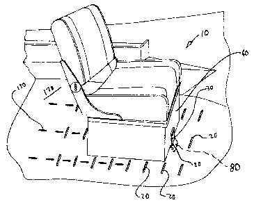
Figure 1 illustrates one embodiment on the present invention. A front side 60
may have a first extension 30 that may extend downwardly to a second extension
80.
The second extension 80 may be removably disposed through a second extension
slot
20. The second extension 80 may extend away from the first extension 30 at an
angle
140, as seen in Figure 3. In one embodiment, that angle 140 may be about 45
degrees.
In another embodiment, that angle may be between about 30 degrees to about 60
degrees. Thus, the seat 10 or component 10 cannot be removed solely by a
vertical
upward force 180.
Figure 1 also illustrates the floor 170 with the finger slot 150. In one
embodiment, the finger slot 150 may be disposed substantially perpendicular to
the
second extension slot 20.
Figure 2 illustrates one embodiment of a method of using the present invention
10, and the structure of one embodiment of the present invention 10. A locking
member 160 may be disposed on a rear side 70. The locking member 160 may
removably secure the seat 10 or component 10 to a floor 170. In one
embodiment, the
locking member 160 may have a tab 50 that can be displaced inwardly along an
inwardly direction 190, which may cause a finger 40 to be displaced outwardly
in an
outwardly direction 200. The finger 40 may extend downwardly to a hook portion
90.
The hook portion 90 may terminate at a tip 100. In one embodiment, the locking
member is J-shaped. For example, the finger 40, the hook portion 90, and the
tip 100
may be J-shaped. Figure 3 illustrates a seat 10 or component 10 that is
secured to a
floor 170. In figure 3, the locking member 160 is illustrated in the secured
position 210.
7
CA 02703678 2010-05-12
As illustrated in Figures 3 and 5, in one embodiment, the hook portion 90 and
tip
100 may be disposed below the floor 170 when the seat 10 is secured to the
floor 170,
which is also referred to as the secured position 210. When the seat 10 is
secured to
the floor 170 in this manner, the locking member 160 is in the secured
position 210. In
one embodiment, the tab 50 can be displaced inwardly, such as by pushing it
with a
thumb with enough force to overcome the force of any spring that may biasly
push the
tab 50 outwardly, or the spring may force the finger 40 inwardly. The locking
member
160 is in the unsecured position when the finger 40 is displaced outwardly,
then the tip
100 would be displaced outwardly, which would cause the tip 100 from being
below the
floor 170, to being below or within the finger slot 150 so that the front side
60 of the
accessory 10 can be lifted upwardly until the second extension 80 is
substantially
vertical. At which point the second extension 80 can be lifted through the
second
extension slot 20. For example, the rear side 70 may be lifted so that the
second
extension 80 is substantially vertical, so that the second extension 80 can be
removed
through the second extension slot 20, and then the seat 10 or component 10 can
be
removed or relocated and repositioned to the floor 170. In one embodiment, the
first
extension 30 is secured to a lower edge 65 of the front side 60.
As seen in Figures 3 and 5, the locking member 160 may have a finger pivot 155
disposed below the tab 50, and above the finger 40 to enable the tab 40 to
bias inwardly
as the finger 40 biases outwardly. Likewise, the finger pivot 155 may allow
the tab 50 to
bias outwardly as the finger 40 may bias inwardly. In one embodiment, a spring
may
exert an outward force above the finger pivot 155, so that the finger 40 has a
hook
8
CA 02703678 2010-05-12
portion 90 secured through a finger slot 150, to secure the seat 10 or
component 10 to
the floor 170.
As seen in Figures 3, 5, and 7, in one embodiment the locking member 160 may
have a hook portion 90 that can fit within a finger slot 150, and then the tip
100 of the
hook portion 90 may contact the bottom side of the floor 110 to secure the
adjustable
seat 10 in place. The first extension 30 may have a second extension 80
extending
therefrom at an outward angle 140. In one embodiment, this angle is called the
angle
between the first extension and the second extension 140. In one embodiment,
this
angle 140 may be about 45 degrees.
Therefore, as seen in Figures 2, 4, and 6, in operation, the second extension
80
may be disposed within a slot 20, then the bottom of the seat 120 may be
placed on the
floor 170, then the hook portion 90 may be placed within the slot 20. The hook
portion
90 may be adjusted or manipulated via a tab 50 that can be displaced in one
direction,
forcing the hook portion 90 to be displaced because of the pivot 130.
Figure 8 further illustrates the seat 10 or component 10 disposed on a floor
170.
The front side 60 is shown having a first extension 30 extending downwardly to
a
second extension 80, and the second extension 80 and first extension 30 may be
disposed whereby there is an angle 140 between them. In one embodiment, this
angle
140 may be about 45 degrees. In one embodiment the angle 140 may be between 30
degrees and 60 degrees. The second extension 80 may be removably disposed
through the second extension slot 20.
Figure 9 illustrates the seat 10 or component 10 secured to a floor 170 by
means
of the locking member 160. The locking member 160 is illustrated in the
secured
9
CA 02703678 2010-05-12
position 210. The locking member 160 may be disposed on the rear side 70. The
finger 40 may be removably disposed through the finger slot 150 of the floor
170.
Figure 10 illustrates another embodiment of the locking member 160. The
locking member may pivot about a pivot 130. The pivot 130 of this embodiment
may be
rotatably disposed to a locking member housing 230. The pivot 130 may be
disposed
above the floor 170, and beneath a fixed end 225. A spring 220 may be biasly
disposed
between the fixed end 225 and a lever member 235. In one embodiment the lever
member 235 may have a contact portion 240, which a boater's finger may contact
to
move the locking member 160. The lever Member 235 may have a horizontal
portion
245 that extends inwardly from the contact portion 240, and the horizontal
portion 245
may be immediately adjacent and above the floor 170. The lever member 235 may
have a hook portion 250 that extends downwardly from the horizontal portion
245. The
hook portion 250 may be able to contact the bottom side of floor 110. For
example the
spring 220 may force the hook portion 250 against the floor 170 to secure the
locking
member 160 in place, which also secures the component or seat 10 in place. The
seat
10 may be removed by forcing the lever portion 240 upwardly, which displaces
the hook
portion 250 away from contact with the bottom side of floor 110, so that the
lever
member 235 may be lifted upwardly through the finger slot 150.
Figure 11 illustrates another embodiment of a locking member 160, where the
finger 40 terminates in an enlarged portion 260, which can be displaced
through a finger
slot keyhole 265 of the finger slot 150. For example, the enlarged portion 260
may have
a diameter smaller then the finger slot keyhole 265, but larger than the width
or
diameter of the finger slot 150.
CA 02703678 2010-05-12
Figure 12 illustrates an embodiment of a seat 10 secured to a floor 170 via
the
locking member 160 with the enlarged portion 260.
Figure 13 illustrates one embodiment with a plurality of combined first
extension
30 and second extensions 80, whereby either the first extension 30 or second
extension
80, or the interface of where the first extension 30 meets the second
extension 80, may
be disposed through the second extension slot 20.
15
11