Note: Descriptions are shown in the official language in which they were submitted.
CA 02703746 2010-05-04
2009/056349 PCT/EP2008/009230
INTERNATIONAL PATENT APPLICATION INCORPORATING
HANDWRITTEN AMENDMENTS
1
Catch, Triggering Mechanism and Handle Piece for a Weapon
The invention relates to a catch for a triggering mechanism, in particular in
the handle
piece of a firearm exhibiting a breech block and a securing device, in
particular of a rapid
fire weapon, wherein the catch can be moved between a position blocking the
breech
block and a position not blocking the breech block.
Positional terms such as "above" "below", "left", "right", "front" and "back"
apply for a
weapon in normal firing position from the point of view of the marksman, said
weapon
firing horizontally toward the "front".
Rapid fire weapons, such as automatic pistols or machine guns, which are
equipped for
the emission of sustained fire, have a rather simple triggering mechanism, of
which in the
following a representative example is described with the help of Figures 13
and 14:
Below the path of motion of the breech block (not shown) there is a handle
piece, in
which a trigger (a) is pivotably mounted. Its transverse pivot axis is located
in the upper
central region of the trigger, so that the rear, upper trigger part travels a
curved path upon
actuation of the trigger. This rear, upper part of the trigger acts on the
front end of a catch
(f) which for its part, is mounted so as to be pivotable around a transverse
axis in the
weapons housing or in the handle piece. The rear end of the catch (f) is
configured as a
sear arm (s). When the trigger (a) is swiveled by a spring in its idle
position toward the
front, then the front end of the catch (f) - likewise under spring action -
swivels
downward and its rear end swivels upward with the sear arm (s). This position
of the sear
arm is the locking position (see Figure 13). The trigger (a) and catch (f) can
each be
cushioned or pre-stressed from a separate or from a common spring and are
pressed by
said spring to their resting position (trigger) or their locking position
(catch).
If now the breech block is pulled back from its front resting position, then
it moves the
sear arm (s) with its underside and with this moves the rear end of the catch
(f)
downward, while it runs over the sear arm (s). When a sear catch, which is
configured on
the underside
CA 02703746 2010-04-26
2
of the breech block, has run across the sear arm (s), then said sear arm snaps
upward and
leaves the sear catch. The weapon is now cocked and ready to fire.
When the trigger (a) is actuated, then the sear arm (s) lowers until it
releases the sear
catch; the breech block is released and the weapon begins sustained fire. When
the trigger
(a) released, then the sear arm (s) springs upward again to its locking
position, leaves the
sear catch and thus keeps the breech block in its ready to fire position (rear
position). As
a result the sustained fire terminates.
Often a pure trigger safety is used as a safety, said trigger safety to be
sure excluding the
unintentional actuating of the trigger, but not a yielding of the sear arm for
example on
the basis of acceleration force, when for example the loaded, cocked and
machine gun
with the safety on falls off a truck.
For this reason there are also safeties (w) which additionally or alone fix
the catch (f) to a
safety finger (i) in its blocking position. However, this has the disadvantage
that the
breech block in the case of a secured weapon cannot be pulled back over the
locked catch
(f) or can get jammed on the catch (f), because said catch cannot dodge.
Figure 13 shows
a safety roller (w) which with its peripheral area shelters a safety finger
(i) of the catch
(f). A weapon with such a safety (w) cannot be cocked and have the cylinder
rotated
when secured.
Fully automatic weapons, which work in accordance with the above described
functional
principle, are being employed increasingly in so-called weapons stations. The
weapons
mounted on gun carriages are remotely oriented via actuators in said weapons
stations
and actuated via actuators acting on trigger and securing device (e.g.
electromagnetically). In order to offer the greatest possible security here as
well, these
actuators are designed in such a way that in the case of malfunctions (e.g.
power failure)
the trigger actuation is interrupted and regardless of the state of the weapon
the securing
device is set to "safety".
Along with the above described problem (no cocking and rotating of cylinder in
the case
of secured weapon), here an additional malfunction can occur that the weapon
even in the
case of interrupted trigger actuation continues firing unchecked. High
actuating forces of
the actuator for the securing device
= CA 02703746 2010-05-04
3
can result in the safety jamming the safety finger (i) in the catch (f) in
such a way that the
sear arm (s) remains out of engagement with the sear catch on the breech
block. This
malfunction can occur when the breech block is back on its way forward
immediately
after trigger actuation and a power failure results in the trigger
simultaneously being
released and the actuator, which acts on the safety, pushes said safety into
its "Securing"
position. In this weapon state the catch (f) and the sear arm (s) are in their
releasing
position and the safety finger (i) plunges into the safety recess on the
securing device
(here the safety roller (w)). If the actuator now sets the safety roller (w)
in the direction of
"safety on", the safety finger (i) blocks its travel distance and the flank of
the safety
recess is under circumstances pressed so firmly against the safety finger (i)
that the catch
(f) I spite of spring action cannot move to its blocking position. The catch
(f) is jammed
over the safety finger (i) and the breech block moves unobstructed back and
forth until
the ammunition supply is interrupted (see Figure 14).
Proceeding from this problem there are trigger devices in which case the sear
arm is
configured on a sear pivotable on the catch (see e.g. DE 101 63 003 Al) and US
2004/0194615 Al or US 6,907,813 B2). In the case of a retreating breech block
this sear
is swiveled from its blocking position against the force of a spring into a
swerving
position, in which it can be overrun by the breech block. In the case of an
advancing
breech block the sear arm of the sear falls into the sear catch under spring
action and is
then additionally held in this blocking position by the breech block. A
securing element is
additionally provided on the sear which cooperates in such a way with the
securing
device (for example a safety roller) that said securing device always -
regardless of the
position of the breech block or of the catch - can be brought to its secured
position. In the
process the securing device can act both on the trigger and on the catch.
In the case of this triggering mechanism an additional spring element is
required in order
to ensure the locking function, and the sear and its swivel suspension must
absorb the full
force of the advancing breech block. In the process the comparatively small
sear and its
suspension are exposed to high dynamic stresses. A fracture or a failure of
the sear, its
suspension in the catch and/or of the spring element in the worst case impact
the weapon
function in such a way,
CA 02703746 2012-05-15
4
that the weapon continues firing regardless of the position of the safety and
the trigger
until its entire ammunition has been fired. In addition the actuating force of
the spring
element must be precisely coordinated to the spring action acting on the
catch. Otherwise
the breech block running over the sear also presses the catch downward into
the handle
piece. In the process under circumstances the cooperation of the securing
element with
the safety roller can be impaired.
The invention, by way of contrast, provides catch for a triggering mechanism
of a firearm
exhibiting a breech block and a securing device, in particular of a rapid fire
weapon,
wherein the catch can be moved between a position blocking the breech block
and a
position not blocking the breech block and is provided with a securing element
which can
be moved relative to the catch between a releasing position (II) and a
securing position
(I), and which occupies its releasing position (II) in the case of a breech
block engaging
on the catch when the retreating breech block exerts an actuating effect on
the securing
element in a rearward direction and does not engage the securing device in the
releasing
position (II), even if said securing device simultaneously occupies its
securing position,
and the catch cannot be brought to its non-blocking position, or occupies its
securing
position (I) in the case of a breech block advancing on the catch when the
breech block
exerts an actuating effect on the securing element in a forward direction and
in the
securing position (I) engages the securing device when said securing device
simultaneously occupies its securing position and fixes the catch itself in
its blocking
position, whereby only said securing element is moveable.
The securing element occupies its releasing position when the retreating
breech block
engages on the catch and exerts an actuating effect on the securing element in
a rearward
direction. In this position (releasing position) the securing element does not
engage on the
securing device, even when said device occupies its securing position, and the
catch can
be moved to its non-blocking position. That is, the breechblock after the
firing-due to
recoil-or for the purpose of cocking and rotating the cylinder can be moved to
the rear
unhindered via the lowering catch.
The securing element on the other hand occupies its securing position in the
case of the
breech block advancing to the catch or adjoining said breechblock, when the
breech block
exerts an actuating effect on the securing element in a forward direction and
moves to the
securing position. In this position (the securing position) the securing
element engages
the securing device, when said securing device simultaneously occupies its
securing
position, and fixes the catch itself in its blocking position.
In the case of this solution the functionslocking of the breech block by the
catch'and the
actual security function`fxing of the catch in the blocking positiori'are
constructively
independent from one another, so that each component or part (here: the catch
and the
securing element) can be optimally configured and designed for its task.
CA 02703746 2012-05-15
The catch can be designed robust and stable for the high stresses which occur
in the case
of interaction with the breech block, while the securing element does not have
to bear any
high mechanical stress through the breech block, but rather above all can be
designed
with regard to the reliable interaction with the securing device.
At the same time this arrangement permits an actuation of the securing device
in any
random function state of the weapon, without components of the securing
element and of
the actual securing device colliding with one another.
Furthermore the latch function of the stable sear arm on the catch is not
impaired in the
case of a malfunction of the securing element. That means the risk of an
unchecked
continuously firing weapon when the trigger is not actuated is to a great
extent ruled out,
at least significantly released in comparison to known solutions from the
state of the art.
Finally a weapon with such a catch can also be cocked and have its cylinder
rotated in the
secured state, and the securing device of the weapon can be actively actuated
in any
function state.
Other improvements in accordance with the present invention increase the
functional
reliability. Either by ensuring through the action of a spring that the
movable securing
element occupies its releasing position (as a consequence of the spring
action) and under
the effect of the forward acting breech block occupies its securing position
against the
spring action. Or inversely, by ensuring through the action of a spring that
the movable
securing element occupies its securing position (as a consequence of the
spring action)
and under the effect of the retreating breech block against the spring action
occupies its
releasing position. Undefined intermediate positions, which potentially impair
the
function, are in this way prevented.
An embodiment in accordance with the present invention has the advantage that
the
securing element only occupies its securing position when the breech block
abuts from
the rear on the catch and with this on the securing element. In other words,
the catch is
freely movable in all other positions of the breech block and there is no
danger
whatsoever of malfunctions: For
CA 02703746 2012-05-15
6
example the above discussed jamming of the breech block on the catch. One
solution in
accordance with the present invention has the advantage that the catch, in the
case of the
securing device occupying its securing position, can only be lowered by means
of the
retreating breech block by having the breech block move the securing element
from its
securing position to its releasing position and thus make the catch movable.
The securing element has a first actuating element which interacts with the
breech block
and via which it can be moved to its securing position, and a securing part
which engages
on the securing device. The first actuating element and securing part can thus
be designed
and arranged in accordance with requirements for their respective function.
The securing element may be arranged in the region of a sear arm configured on
the
catch, engaging engaged on the breech block in the blocking position. Such a
sear arm is
particularly suitable for stable engage on the breech block. Through the
arrangement of
the securing element in this region the breech block can bring about, with the
same active
areas which make possible its locking on the sear arm or on the catch, the
movement of
the securing element to the securing position.
Through another improvement in accordance with the present invention the
functional
reliability of the securing element is increased once again by reducing the
stress of the
first actuating element actuating element. This is managed as a result of the
fact that the
first actuating element in the case of an adjoining breech block lies within
the sear arm
profile. In the process the blocking or locking function on the breech block
is exerted
exclusively via the sear arm; the securing element does not experience any
additional
loads and in particular does not absorb any applied loads through the breech
block spring
via the breech block to the catch or the sear arm.
In a further improvement in accordance with the present invention a second
actuating
element is provided on the securing element, said element being drivable by
the retreating
breech block and as a result the securing element being moveable itself to its
releasing
position, so that a securing part also in the case of occupied securing
position of the
securing element lies outside the active area of the securing device. Here too
an
advantageous functional separation is realized in which the first actuating
element and the
second actuating element assume different functions. In addition a functional
separation
is also realized between the
CA 02703746 2012-05-15
7
depressing of the catch (for which relatively great forces are necessary) and
the deflection
of the securing element to its releasing position. As a result the second
actuating element
can be actuated comparatively low in load and precisely by the retreating
breech block.
In accordance with another embodiment of the present invention the process the
second
actuating element is configured as a control cam, which interacts with a
corresponding
control profile on the breech block. control cam and control profile can in
the process be
strictly coordinated to one another, in order for example to guarantee that
the emergency
and auxiliary locking functions of the breech block on the catch remain
uninfluenced. In
addition a corresponding control profile can also be mounted subsequently on
already
available breech block elements, in particular can be milled in.
The configuration of the securing element as a slide in accordance with a
further
embodiment permits a functionally reliable, shielded arrangement of the
securing element
in the catch. Preferably the sliding direction in the process proceeds
somewhat in the
barrel direction of the breech block, as a result of which the stress of the
securing element
I the case of actuation by the breech block can be kept as low as possible.
Moreover, the securing element may be configured as a pivot lever.
The pivot axis proceeds in the process transversely to the barrel direction of
the breech
block. With this the actuation direction for the pivot lever also runs
corresponding to the
barrel direction of the breech block.
Through a configuration as a two-armed pivot lever the actuation direction (of
the
advancing breech block) can be redirected to another running safety direction
of the
second lever arm. For this purpose the two lever arms can for example form an
angle to
one another. Thus specific constructive marginal conditions, which under
circumstances
are given by the securing device, can be flexibly considered.
If the lever arms are different in length, the travel distance and safety
distance can also be
different in length. In particular whenever the
CA 02703746 2012-05-15
8
first lever arm exhibiting the actuating element is configured shorter than
the second
lever arm exhibiting the securing part, the travel distance can be
comparatively short and
the required safety distance can be designed so long through the corresponding
selection
of the lever proportions that sufficiently large distances are available in
order to exit the
active area of the securing device or to reach said active area. With this the
securing part
can also be configured correspondingly large in area or stable with regard to
the required
active areas and its mechanical stress.
The pivot axis can in one embodiment also by the focal point of the pivot
lever, thus said
pivot lever is dynamically balanced, i.e. lateral accelerations acting on the
weapon can
not move the pivot lever from its securing position.
The self locking design of the active areas on the securing part or the
corresponding
counter surface on the securing device relevant for the securing action
further increases
the securing action. It prevents-even in the case of a high load of the sear
arm against the
securing action-the active area of the securing part and the counter surface
of the
securing device from sliding from one another and thus disturbing the security
function.
Such loads can for example occur in the case of high dynamic stresses (blows)
on the
weapon or, if the trigger is supposed to act with high force against the
securing action on
the catch, for example when the trigger is actuated by motor against the
securing device.
The present invention also relates to a triggering mechanism with an inventive
catch.
The present invention further relates to a handle piece with an inventive
triggering
mechanism which for example in the case of the corresponding design can be
exchanged
for a conventional handle piece without the specified security function. It is
provided
with one or more interfaces via which the trigger or the securing device can
be coupled
directly or indirectly with an actuating element for its actuation. A weapon
with such a
handle piece is particularly suitable for a so-called weapons station.
The present invention also provides a weapon with an inventive catch, an
inventive
triggering mechanism or an inventive handle piece.
CA 02703746 2010-04-26
9
Exemplary embodiments of the present invention will be described with the help
of the
drawings. The figures show the following:
Figure 1 shows a schematic lateral view of a handle piece (partially cutaway)
with an inventive trigger device, in which case the securing element is
configured as a slide,
Figure 2 shows a schematic lateral view of a handle piece with another
inventive
trigger device, in which case the securing element is configured as a
pivot lever, the catch in its blocking position with caught breech
block and the securing device in the "Safe" position A,
Figure 3 shows the triggering mechanism from Figure 2, in which case the
securing
device is in the "Fire" position B,
Figure 4 shows the triggering mechanism from Figure 2, in which case the
breech
block is released, the trigger is actuated and the securing device is in the
"Fire" position B,
Figure 5 shows the triggering mechanism from Figure 4, in which case the
trigger
is released, the release catch is locked into position with the catch and
the safety device is in the "Safe" position A,
Figure 6 shows the triggering mechanism from Figure 5, in which case the
retreating breech block has moved the catch to its blocking position by
actuation of the release catch,
Figure 7 shows the triggering mechanism from Figure 6, in which case the
retreating breech block has deflected the catch engaged on the sear arm
from the blocking position and the securing device is in the "Safe"
position A,
CA 02703746 2010-05-04
Figure 8 shows a schematic lateral view of a handle piece (partially cutaway)
with an inventive catch, in which case the securing element is
configured as a pivot lever and in its blocking position the catch with
caught breech block and the securing device is in its securing position,
Figure 9 shows a schematic lateral view of the triggering mechanism from
Figure 8,
in which case the catch is shown in its non-blocking position with
retreating breech block and the securing device is in the securing position,
Figure 10 shows a schematic lateral view of a further exemplary embodiment of
an
inventive trigger device, in which case the security function and the trigger
function takes place via remote actuated guide bars and the securing
device is in the fire position B,
Figure 11 shows the triggering mechanism from Figure 10, in which case the
securing device is in the safe position A,
Figure 12 shows a perspective view of the configuration shown in Figure 10,
Figure 13 shows a conventional triggering mechanism in a sectional
representation,
in which case a safety roller is in the "Safe" position and
Figure 14 shows the triggering mechanism from Figure 13, in which case the
catch is
shown jammed in the safety roller via its safety nose.
The structure and function of the inventive catch 21 or of the triggering
mechanism will
be explained with Figure 1 (First exemplary embodiment), 2 through 7 (second
exemplary embodiment), 8 and 9 (third exemplary embodiment) and 10 through 13
(fourth exemplary embodiment) with the help of four exemplary embodiments.
Identical
reference numerals apply to identical or identically functioning components.
CA 02703746 2010-04-26
11
In accordance with Figure 1 the handle piece 1 is mounted on a housing of a
weapon not
shown in the figure, in which housing a path of motion is defined for the
partially shown
breech block 3. The path of motion of the breech block runs along the axis of
the bore 5.
The handle piece exhibits on its front side a t rigger guard 7, into which
from above the
handle piece 1 a trigger 9 plunges, said trigger being pivoted around a
trigger axis 11 in
the handle piece 1 running transversely to the axis of the bore 5. A torsion
spring 13,
whose two legs encompass a cross pin 17, and said torsion spring being thus
fixed in the
handle piece 1, presses with its lower spring leg 15 the trigger 9 forward.
The upper
spring leg 19 presses a two-arm catch 21 engaged on its rear lever arm 23
counter-
clockwise upward to its blocking position. The front lever arm 25 runs above
the trigger
axis 11 and a release roller 27, which is seated on the trigger 9. The catch
21 itself is
pivoted on a lever axis 29 transverse to the axis of the bore 5 in the handle
piece 1.
If the trigger 9 is actuated and in the process swiveled against the force of
the torsion
spring 13 counter-clockwise, then the release roller 27 raises the front lever
arm 25
against the force of the torsion spring 13 and lowers the end of the rear
lever arm 25 (this
position is shown in Figure 4 in conjunction with the second exemplary
embodiment). On
the rear end of the rear lever arm 23 a sear arm 31 is shown, which leaves a
sear catch 33
on the breech block 3 and holds said sear catch in its cocked, ready-to-fire
position
(Figure 1). In the case of the lowering of the sear arm 31 through the trigger
movement
the breech block 3 is released, after that moves forward in the weapons
housing under the
influence of the breech block spring not shown in the figure, feeds the
ammunition and
finally ignites (with the help of the firing pin not shown in the figure) the
propellant (see
Position Figure 4).
In the case of the lowering of the rear end 23 of the catch 21 its front end
21 is raised and
gripped from below on a latching catch 51 provided there by a release catch
53. The
release catch 53 is pivotably suspended on the trigger 9 around a pin 54
against the force
of a catch spring 55. After the release of the trigger 9 the release catch 53
holds the rear
end 23 and the sear arm 31 of the catch 21 outside the path of motion of the
breech block
(Figure 5).
CA 02703746 2010-04-26
12
Not until the breech block 3 runs rearward does it meet the release catch 53
and swivel
said release catch clockwise against the force of the catch spring 55 and
release the
latching catch 51 on the catch 21, said catch springs counterclockwise with
its rear end 23
in the path of motion of the breech block 3 (see Figure 6). In the process the
sear catch 33
of the breech block 3 overruns the sear arm 31, which plunges elastically
downward into
the handle piece (see Figure 7) until the forwardmost sear catch 33 on the
breech block 3
has completely overrun the sear arm 31, the catch 21 occupies its blocking
position and
the sear arm 31 engages the sear catch 33 and thereon engaged can keep the
breech block
in the rearmost position.
In the case of the triggering mechanism of the first exemplary embodiment
(Figure 1) a
slide 101 is arranged in the rear end of the rear lever arm 23, whose rear
abutting surface
103 forms an actuating element on which the adjoining sear catch 33 can
engage. In its
idle position (II) the slide 101 protrudes under the effect of a spring
arrangement 104
running in the interior of the rear lever arm 23 by the amount D to the rear
from the rear
lever arm 23.
The sear catch 33 of the breech block pressing from the rear against the rear
abutting
surface 103 of the slide 101 moves the slide 101 against the effect of the
spring
arrangement 104 in the direction of the axis of the bore 5 by the amount D to
the rear
lever arm into the securing position I of the slide. In this position its rear
abutting surface
103 ends with the rear abutting surface of the sear arm 31, so that the
actuating element
lies completely within the sear arm profile. The rear abutting surface of the
sear arm 31 in
the process prevents the breech block from moving further forward when the
sear arm 31
is in its blocking position (see Figures 1, 2 and 3). Simultaneously in this
way it is
ensured that the slide 101 itself is only slightly strained by the advancing
or adjoining
breech block 3. The load of the slide 101 itself results only from the
restoring force of the
spring arrangement 104, which must overcome the advancing breech block 3. On
the
other hand the sear arm 31 or the catch 21 experiences the essential load and
stress
through the breech block 3. With this the risk of an overload or a malfunction
of the slide
101 is minimized.
The slide 101 exhibits a finger 105 running downward proceeding from the
actuating
element (here: its rear abutting surface), said finger forming a securing part
and
interacting with a
CA 02703746 2010-04-26
13
securing device 40. The represented securing device 40 comprises a safety
roller 41
which is provided with a recess 43. Rotationally fixed to the safety roller 41
are a
latching lug 45 and an actuating lever protruding from the housing (not shown
in the
figure), via which the safety roller 41 can be rotated between the "Safe" and
the Fire
position. These two positions are defined by two recesses 49 on the latching
lug 45 and a
stationary spring-loaded catch arrangement 47, each of which engages into one
of the two
recesses 49.
In addition the latching lug 45 exhibits a safety lug 46. When the securing
device is in its
"Safe" position (position in Figure 1), the safety lug 46 leaves a
corresponding safety
extension 10, which protrudes from the trigger 9 to the rear into the housing
1.
The slide 101 interacts via its finger 105 in the following way with the
securing device
40:
- In the case of a cocked weapon with rotated cylinder the breech block 3
adjoins
with its sear catch 33 at the rear abutting surface of the sear arm 31 and the
rear
abutting surface 103 of the slide 101, said slide occupying the Safe position
(Position I). The finger 105 is located here in the active area of the
securing
device 40. The recess 43 in the safety roller 41 is in the "Safe" position
(Position
A). The finger 105 adjoins with its active area 105a at the exterior
peripheral area
of the safety roller 41. With this the slide 101 supports the rear lever arm
23 and
with it the sear arm 31 downward against the safety roller 41. The sear arm
cannot
be moved from its blocking position; not even if the additional trigger safety
which is formed by the safety lug 46 and the safety extension 10 were to be
omitted and the trigger 9 were pressed.
- If now the securing device is moved to its "Fire" position by rotating the
safety
roller 41, the recess 43 occupies position B and is in the region of the
finger 105;
simultaneously the safety lug 46 occupies a position lying outside the active
area
of the safety extension 10 (not shown in Figure 1, see Figure 3).
CA 02703746 2010-04-26
14
- If now the trigger 9 is actuated, the front lever arm 25 of the catch 21 is
pressed
upward clockwise via the trigger roller 27 and the rear lever arm 23 with the
sear
arm 31 and the slide 101 is swiveled downward into the housing 1. In the
process
the finger 105 enters into the recess 43 in the safety roller 41, the breech
block 3
is released and moves forward (see Figure 4).
- In the process the front lever arm 25 is caught with the latching catch 51
in the
release catch 53 so that the catch 21 with the sear arm 31 remains within the
handle piece 1 in the case of released trigger 9 (this position is shown
analogously
in Figure 5).
- The slide 101 occupies its idle position, in which its rear abutting surface
103
protrudes to the rear from the sear arm 31 and the finger 105 runs outside of
the
active area of the securing device 40 (Position II, shown drawn through in
Figure
1).
- In the case of normal weapon function the breech block moving forward feeds
a
new round, is then launched to the rear again by the recoil occurring during
firing
and in the process triggers the release catch 53, which releases the latching
catch
51. As a result - under the influence of the upper spring leg 19 of the leg
spring
13 the catch 21 moves upward with its rear lever arm 23. The retreating breech
block 5 in the process moves the rear lever arm 23 downward again to be
precise
via correspondingly configured oblique contact members 32, which run up to the
rear somewhat obliquely from sear catch edge. In the process the breech block
spring is cocked until the movement of the breech block 3 reverses again and
the
sear catch 33 adjoins the rear abutting surface of the sear arm 31 and in the
process moves the slide 101 to its rear abutting surface 103 forward into the
left
lever arm 23.
In the case of a malfunction (misfire, malfunction when advancing etc.) the
breech block 3 does not retreat, but rather remains between the trigger
arrangement and chamber. Also in this case the securing device 40 can be
actuated, since the finger 105 is in its idle position II outside of the
active area of
the safety roller 41. The slide 101 does not hinder the actuation of the
securing
device 40. The securing device 40 can be moved from the "Fire" to the Safe"
position.
CA 02703746 2010-04-26
- In order to remedy the malfunction, the breech block is manually returned
(cocked with the cylinder being rotated). In the case racking likewise the
release
catch 53 is actuated and the rear lever arm 23 dips with the sear arm 31 from
the
housing profile upward to the path of motion of the breech block. The racking
is
also possible in the "Safe" position of the securing device 40, since the
slide 101
with the finger 105 is in its idle position II outside of the active area of
the
securing device 40 and the lowering movement exerted on the rear lever arm 23
by the safety roller 41 in the case of cocking and rotating the cylinder is
not
hindered.
- After the racking the sear arm 33 of the breech block 3 again adjoins the
sear arm
31 of the catch 21, after previously moving the slide 101 at the rear abutting
surface 103 engaging into the catch 21 to its securing position. The finger
105
(shown in dashed lines in its securing position in Figure 5) is located in the
active
area of the securing device 40 and the weapon is immediately in secured state.
- Now all necessary tasks can be carried out without risk in the front region
of the
weapon, without the breech block 3 being triggered by accidental actuation of
the
trigger 9.
- Via the slider 101 which can be moved relative to the sear arm 31 with the
finger
105 engaging the securing device 40 the following is ensured: For one thing
the
weapon can be racked also in secured state, since the slide 101 with the
finger 105
is not in the active area of the securing device 40 until the breech block 3
with its
sear catch 33 has moved the rear abutting surface 103 of the slide 101 into
the
catch 21 so far that said catch is flush with the rear abutting surface of the
sear
arm 31 and the sear catch 33 hence adjoins the sear arm 31. For another thing,
the
weapon can be secured in any state, even if the breech block 3 is in front of
the
handle piece and the rear lever arm 23 is lowered in the handle piece 2, since
the
slide 101 in its idle position with the finger 105 runs outside of the active
area of
the securing device 40.
CA 02703746 2010-04-26
16
In the second exemplary embodiment shown in Figures 3 through 7 instead of the
slide
101 a tow-armed pivot lever 201 is provided, which is arranged around a pivot
axis 202
running transversely to the axis of the bore 5 in the rear lever arm 23 of the
catch 21. An
upper lever arm 203 of the pivot lever 201 in the process forms with its rear
abutting
surface the actuating element at which the sear catch 33 in the case of the
breech block 3
adjoining the sear arm 31 moves the pivot lever 201 against the force of a
spring
arrangement 204 to the securing position so that a lower lever arm 205 of the
pivot lever
201 moves as a securing part into the active area of the securing device 40
(see Figures 2
and 3). In this position the upper pivot lever arm 203 plunges completely into
the profile
of the sear arm 31.
If the breech block 3 with its sear catch 33 does not adjoin the sear arm 31,
the pivot lever
201 occupies its idle position under the effect of the spring arrangement 204,
in said
position which the lower lever arm 205 lies outside of the active area of the
securing
device 40 and the upper lever arm 203 partially protrudes to the rear from the
profile of
the sear arm (Figures 4 through 7).
The functionality of this securing device is analogous to the securing device
described in
conjunction with the first exemplary embodiment. With the pivot lever 201
however very
short travel distances of the upper lever arm 203 can be realized, by
constructing the
lower lever arm 205 longer than the upper lever arm 203. A short pivoting path
of the
upper lever arm 203 in the process produces a long pivoting path of the lower
lever arm
205.
The travel distance can be so short that the overlap with the sear catch 33 of
the retreating
breech block 3 only extends minimally to the rear vis-a-vis a catch (f)
without pivot lever
21 - as shown in Figures 13 and 14. With this the breech block arrangement in
accordance with Figures 2 through 9 can be exchanged for the breech block
arrangement
represented in Figures 13 and 14 without further adaptations. Conveniently,
for this
purpose only the handle piece must be exchanged.
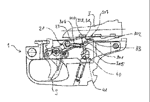
Figures 8 and 9 show a further exemplary embodiment of a handle piece 1 which
in its
structure and in its function corresponds essentially to the one shown in
Figures 2 through
7. However, a pivot lever 301 is provided here at
CA 02703746 2010-04-26
17
whose lower lever arm 305 a spring arrangement 304 engages (in the rear end 23
of the
catch 21). This spring arrangement 304 presses the pivot lever 301 counter-
clockwise to
its securing position. This means that the catch 21 - regardless of the
position of the
breech block 3 - will always be held in its blocking position when the
securing device 40
occupies its securing position (See Figures 8 and 9).
So that the retreating breech block is not hindered by the catch 21 thus fixed
in its
blocking position, the following is provided: On the pivot axis 302 of the
pivot lever 301
a second actuating element 306 configured here as a control cam is arranged
together
with the first actuating element 303. The first and second actuating elements
303, 306 are
jointly pivotable around the pivot axis 302. That is, the pivot lever 301 can
be diverted by
the second actuating element 306. If this takes place clockwise, the lower
lever arm 305
goes out of engagement with the securing device 40 and releases the catch 21,
so that its
rear end 23 or the sear arm 31 can be lowered. In the shown exemplary
embodiment this
takes place via a control profile 307 constructed on the breech block 3, said
control
profile's contour being adapted to the course of the sear catch profile (of
the sear catch
33) on the underside of the breech block 3. Figure 9 shows a breech block
position in
which case the retreating breech block 3 (in the direction of the arrow)
engages with the
control profile 307 on the control cam (the second actuating element 306) and
deflects the
pivot lever 301 clockwise against the spring arrangement 304 and moves the
pivot lever
301 to its release position (II) in which it does not engage the securing
device 40 with its
lower lever arm 305. Simultaneously the sear catch 33 presses the rear end 23
of the
catch downward.
The breech block 3 travels so far back until the second actuating element 306
(the control
cam) falls into a recess 307a of the control profile 307. Simultaneously the
catch 31 is
pressed upward with its rear end 23 under the effect of the trigger spring
(torsion spring
13). The sear arm 31 falls in before the sear catch 33 and blocks the
advancement of the
breech block 3. The pivot lever 301 resumes its securing position and the
catch 21 is
blocked in its blocking position as long as the securing device 40 is in its
securing
position. In addition to the spring arrangement 304 the front edge of the sear
catch 33
also presses on the upper pivot lever arm 303 and presses said pivot lever arm
into the
profile of the sear arm 31 (compare the second exemplary embodiment
represented in
Figures 2 through 7).
CA 02703746 2010-04-26
18
The second actuating element (of the control cam 306) makes possible in the
case of this
exemplary embodiment a reliable control of the pivot lever 301 also without
the spring
arrangement 304 (Figures 8 and 9). For the pivot lever 301 is reliably brought
to its
releasing position by the control profile 307 in the case of the retreating
breech block 3
(Figure 9) and in the case of an advancing breech block via one of the sear
catches 33,
which engages on the first actuating element 303 (upper pivot lever arm), and
brings the
securing element 301 (pivot lever) to its securing position. This means, the
desired
securing function is reliably guaranteed without spring arrangement 304 or
also in the
case of malfunctions (broken springs).
In the above described exemplary embodiments the securing device is configured
as a
rotatable safety roller 41 with corresponding recesses 43. There are other
embodiments in
which the securing device is configured as a slide safety in which case a
corresponding
securing profile is configured either to the axis of the bore 5 or also
parallel to the axis of
the bore 5. Such a securing slide then exhibits a corresponding securing
profile with
recesses and active areas which, analogous to the described safety roller 41
interacts with
the securing element arranged on the catch 21 (for example a slide 101 or a
pivot lever
201). Such a securing slide can also be directly coupled to a corresponding
actuator
which for example controls the weapon in a weapons station. There are also
embodiments
in which case separate interfaces are provided on the trigger 9, at which such
actuators
can be arranged.
Figures 10 through 12 show a fourth exemplary embodiment of a handle piece 1
with an
inventive catch 21. Here it is a matter of a so-called machine handle piece
which for
example is inserted into a weapon which can be used in a so-called weapons
station. The
trigger 109 is formed by a bracket 109a fixed on an actuating bar 109c with a
trigger
element 109b hinged thereon. The catch 21 and pivot lever 201 correspond in
their
function - with slightly transformed geometry - to the exemplary embodiment
represented in connection with Figures 2 through 7. However the safety roller
40 is
replaced here by a
CA 02703746 2010-04-26
19
securing slide 140 which can be actuated via a securing bar 141. Figure 10
shows the
handle piece 1, in which case the securing device 40 occupies its Fire
position (safety
off). In the case of the movement of the actuating bar 109c in the direction
of the arrow
said actuating bar pulls via the bracket 109a on the trigger element 109b and
raises the
catch 21 over the release roller 27 on its front end, so that the rear end 23
is lowered in
known manner and a (not shown in the figure) trigger 3 is released.
In Figures 11 and 12 the securing device 140 occupies its securing position
and shelters
the pivot lever 201 or its lower lever arm 205, when the breech block 3
adjoins on the
rear end of the catch 21 and brings the pivot lever 201 to the position shown
drawn
through. It is not possible to fire. If the breech block 3 does not adjoin the
rear end 23 of
the catch 21, the spring arrangement 204 moves the pivot lever 201 to the
position shown
in dot-dashed lines (Figure 11) and the lower end 205 of the pivot lever 201
can plunge
past the securing slide 140 downward into the handle piece 1, even if the
securing slide
140 occupies its secured position. A retreating breech block 3 is not
hindered. The
securing bar securing bar 141 and the trigger bar 109c are coupled here to
corresponding
actuators (not shown in the figure), via which said actuators they can be
actuated.
The actuators and the securing bar 141 and the trigger bar 109c are controlled
so that in
the case of a malfunction (power failure, cable break, other malfunction) the
trigger bar
109c is moved counter to the direction of the arrow (Fire setting) and the
securing slide
140 is brought to the securing position shown in Figures 11 and 12. this is
always
possible through the inventive catch 21, without having to pay attention to
the breech
block position or movement. Malfunctions and the position of the trigger bar
109c of the
securing bar 141 or of the securing bar 140 can be registered by sensors and
corresponding signals can be processed in a control system.
Further embodiments and variations of the present invention arise for the
person skilled
in the art within the scope of the claims.