Language selection

Search

Patent 2704259 Summary

Third-party information liability

Some of the information on this Web page has been provided by external sources. The Government of Canada is not responsible for the accuracy, reliability or currency of the information supplied by external sources. Users wishing to rely upon this information should consult directly with the source of the information. Content provided by external sources is not subject to official languages, privacy and accessibility requirements.

Claims and Abstract availability

Any discrepancies in the text and image of the Claims and Abstract are due to differing posting times. Text of the Claims and Abstract are posted:

  • At the time the application is open to public inspection;
  • At the time of issue of the patent (grant).
(12) Patent Application: (11) CA 2704259
(54) English Title: PARKING STALL BARRIER
(54) French Title: BARRIERE POUR PLACE DE STATIONNEMENT
Status: Deemed Abandoned and Beyond the Period of Reinstatement - Pending Response to Notice of Disregarded Communication
Bibliographic Data
(51) International Patent Classification (IPC):
  • E01F 13/00 (2006.01)
  • E01F 13/04 (2006.01)
(72) Inventors :
  • GOODMAN, WAYNE (Canada)
  • HOUSE, VINCENT E. (Canada)
(73) Owners :
  • WAYNE GOODMAN
  • VINCENT E. HOUSE
(71) Applicants :
  • WAYNE GOODMAN (Canada)
  • VINCENT E. HOUSE (Canada)
(74) Agent: NATHAN V. WOODRUFFWOODRUFF, NATHAN V.
(74) Associate agent:
(45) Issued:
(86) PCT Filing Date: 2008-10-24
(87) Open to Public Inspection: 2009-05-07
Availability of licence: N/A
Dedicated to the Public: N/A
(25) Language of filing: English

Patent Cooperation Treaty (PCT): Yes
(86) PCT Filing Number: PCT/CA2008/001883
(87) International Publication Number: WO 2009055905
(85) National Entry: 2010-04-30

(30) Application Priority Data:
Application No. Country/Territory Date
60/984,100 (United States of America) 2007-10-31

Abstracts

English Abstract


A parking stall barrier includes an elongated horizontal member and a pair of
supports. The pair of supports are
positioned in spaced relation and support the opposed ends of the horizontal
member. The horizontal member is movable vertically
along the supports between a raised barrier position and a lowered access
position. A locking latch mechanism secures the horizontal
member in the raised barrier position. When the locking latch mechanism is
released, the horizontal member can be moved from the
raised barrier position to the lowered access position to facilitate vehicle
ingress and egress.


French Abstract

L'invention concerne une barrière pour place de stationnement comprenant un élément horizontal allongé et une paire de supports. Les deux supports sont disposés de manière espacée et ils supportent les extrémités opposées de l'élément horizontal. Ledit élément horizontal peut être déplacé verticalement le long des supports, entre une position de barrière haute et une position de passage basse. Un mécanisme de verrouillage fixe l'élément horizontal dans la position de barrière haute. Lorsque le mécanisme verrouillage est libéré, l'élément horizontal peut être déplacé de la position de barrière haute à la position de passage basse pour permettre l'entrée et la sortie d'un véhicule.

Claims

Note: Claims are shown in the official language in which they were submitted.

5
What is Claimed is:
1. A parking stall barrier, comprising:
an elongated horizontal member having opposed ends;
a pair supports positioned in spaced relation and supporting the opposed ends
of the
horizontal member, the horizontal member being movable vertically along the
supports
between a raised barrier position and a lowered access position;
a locking latch mechanism securing the horizontal member in the raised barrier
position;
means for releasing the locking latch mechanism to enable the horizontal
member to
be moved from the raised barrier position to the lowered access position to
facilitate vehicle
ingress and egress.
2. The parking stall barrier of Claim 1, wherein springs bias the horizontal
member into the
raised barrier position, pressure from vehicle tires being able to temporarily
overcome the
biasing force of the springs to move the horizontal member from the raised
barrier position to
the lowered access position when the locking latch mechanism is released.
3. The parking stall barrier of Claim 1, wherein the locking latch mechanism
comprises a
lock controlled by a solenoid and the means for releasing the locking latch
mechanism is a
wireless actuator capable of actuating the solenoid remotely.
4. The parking stall barrier of Claim 1, wherein the supports are a pair of
hollow support
posts each having a side wall that defines an interior cavity with a vertical
opening through
which one of the opposed ends of the horizontal member extends into the
interior cavity, the
horizontal member being movable along the vertical opening between the raised
barrier
position and the lowered access position.
5. A parking stall barrier, comprising:
an elongated horizontal member having opposed ends;

6
a pair supports positioned in spaced relation and supporting the opposed ends
of the
horizontal member, the supports being a pair of hollow support posts each
having a side wall
that defines an interior cavity with a vertical opening through which one of
the opposed ends
of the horizontal member extends into the interior cavity, the horizontal
member being
movable vertically along the vertical opening between a raised barrier
position and a lowered
access position;
springs biasing the horizontal member into the raised barrier position;
a locking latch mechanism securing the horizontal member in the raised barrier
position, the locking latch mechanism having a latch controlled by a solenoid;
a wireless actuator capable of actuating the solenoid remotely to release the
latch on
the locking latch mechanism to enable pressure from vehicle tires to
temporarily overcome
the biasing force of the springs to move the horizontal member from the raised
barrier
position to the lowered access position to facilitate vehicle ingress and
egress.
6. The parking stall barrier of Claim 5, wherein the horizontal member has a
transverse
curvature.
7. The parking stall barrier of Claim 5, wherein a flexible ground engaging
shroud overlies
the horizontal member.
8. The parking stall barrier of Claim 5, wherein signage is supported by the
supports.

Description

Note: Descriptions are shown in the official language in which they were submitted.


CA 02704259 2010-04-30
WO 2009/055905 PCT/CA2008/001883
1
TITLE:
Parking Stall Barrier
FIELD
The present invention relates to a barrier which prevents persons from parking
their
vehicles in reserved parking stalls.
BACKGROUND
Some drivers do not respect signs designating reserved parking stalls. To
address this
problem a number of devices have been proposed, as described in the following
patents:
U.S. 3,849,936; U.S. 4,531,472; U.S. 4,713,910; U.S. 4,879,554; U.S.
5,165,200; and U.S.
6,142,702.
SUMMARY
There is provided a parking stall barrier which includes an elongated
horizontal
member and a pair of supports. The pair of supports are positioned in spaced
relation and
support the opposed ends of the horizontal member. The horizontal member is
movable
vertically along the supports between a raised barrier position and a lowered
access position.
A locking latch mechanism secures the horizontal member in the raised barrier
position.
When the locking latch mechanism is released, the horizontal member can be
moved from
the raised barrier position to the lowered access position to facilitate
vehicle ingress and
egress.
BRIEF DESCRIPTION OF THE DRAWINGS
These and other features will become more apparent from the following
description
in which reference is made to the appended drawings, the drawings are for the
purpose of
illustration only and are not intended to in any way limit the scope of the
invention to the
particular embodiment or embodiments shown, wherein:
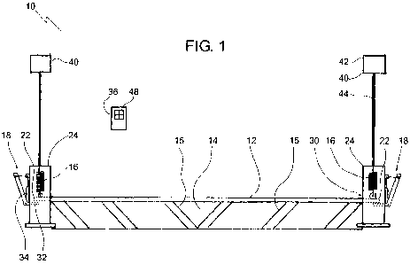
FIG. 1 is a front elevation view of a parking stall barrier.
FIG. 2 is a side elevation view, in section, of the parking stall barrier of
FIG. 1 in a
raised barrier position.

CA 02704259 2010-04-30
WO 2009/055905 PCT/CA2008/001883
2
FIG. 3 is a side elevation view, in section, of the parking stall barrier of
FIG. 1, in a
lowered access position.
DETAILED DESCRIPTION
A parking stall barrier generally identified by reference numeral 10, will now
be
described with reference to FIG. 1 through 3.
Structure and Relationship of Parts:
Referring to FIG. 1, parking stall barrier 10 consists of an elongated
horizontal
member 12 having opposed ends 22. A pair supports are positioned in spaced
relation and
support opposed ends 22 of horizontal member 12. In the illustrated
embodiment, the
supports are a pair of hollow support posts 24. Referring to FIG. 2, each
support post 24 has
a side wall 26 that defines an interior cavity 28. Referring to FIG. 1, a
vertical opening 30 is
provided in side wall 26 through which one of opposed ends 22 of horizontal
member 12
extends into interior cavity 28. Referring to FIG. 2 and FIG. 3, horizontal
member 12 is
movable vertically within vertical opening 30 between a raised barrier
position depicted in
FIG. 2 and a lowered access position depicted in FIG. 3. Springs 16 bias
horizontal member
12 into the raised barrier position illustrated in FIG. 2. Referring to FIG.
1, a locking latch
mechanism 18 maintains horizontal member 12 in the raised barrier position.
Locking latch
mechanism 18 has a latch 32 controlled by a solenoid 34. A wireless actuator
36 is used to
remotely actuate solenoid 34 to release latch 32 on locking latch mechanism
18. Referring to
FIG. 2, while horizontal member 12 can be make in a variety of configurations,
it is
preferred that horizontal member 12 be made with a transverse curvature which
provides
strength and facilitates a vehicle passing over it. For aesthetic reasons, it
is also preferred
that a flexible ground engaging shroud 14 overlie horizontal member 12 and
carry markings
15 which make horizontal member 12 of parking stall barrier 10 highly visible.
Finally it is
preferred that signage 40 be supported by support posts 24, with a message
that warns that
the parking stall is reserved. In the illustrated embodiment, signage 40 has a
message portion
42 and a shaft portion 44, which raises message portion 42 to eye level.
Operation:
The use and operation of parking stall barrier 10 will now be described with

CA 02704259 2010-04-30
WO 2009/055905 PCT/CA2008/001883
3
reference to FIG. 1 through 3. Referring to FIG. 1, with horizontal member 12
locked in the
raised barrier position, parking stall barrier 10 serves as a barrier to
prevent unauthorized
entry of a vehicle into a parking stall. A person authorized to use the
parking stall, pushes a
button 48 on wireless actuator 36. Wireless actuator 36 then sends a signal
caused acutate
solenoid 34 to release locking latch mechanism 18 by moving latch 32 from
under horizontal
member 12. Referring to FIG. 2 and FIG. 3, once locking latch mechanism 18 is
released,
pressure from vehicle tires 38 temporarily overcome the biasing force of
springs 16 to move
horizontal member 12 from the raised barrier position depicted in FIG. 2 to
the lowered
access position depicted in FIG. 3 to facilitate vehicle ingress and egress.
When horizontal
member 12 moves into the lowered access position, shroud 14 flattens, allowing
vehicle tires
38 to pass smoothly overtop. Once vehicle tires 38 have passed over horizontal
barrier 12,
springs 16 bias horizontal member 12 back into the raised barrier position
illustrated in FIG.
3 and locking latch mechanism 18 automatically is re-engaged.
Barrier 10 may be provided to prevent unauthorized entry into any type of
space.
Examples of various types of spaces that barrier 10 may be used with include
private
apartment, company, and handicapped parking. Barriers 10 may be used
singularly or in
multiples. Barrier 10 has the advantage of removing the need for a manned
security post.
Any attempt to compromise barrier 10 may activate a pressure sensitive switch
mechanism
(not shown) that may in turn activate an alarm. Alternatively, an alarm could
be activated by
motion or heat sensors.
Barrier 10 may also function as an anti-theft device. Once a vehicle is locked
in by
barrier 10, a thief cannot easily remove the vehicle from behind barrier 10. A
panic button
may be provide on wireless actuator 36 in order to allow a user to activate
the alarm if
suspicious activity is spotted by the user. Barrier 10 may also be provided
with, or installed
as part of, a surveillance system.
In this patent document, the word "comprising" is used in its non-limiting
sense to
mean that items following the word are included, but items not specifically
mentioned are
not excluded. A reference to an element by the indefinite article "a" does not
exclude the
possibility that more than one of the element is present, unless the context
clearly requires

CA 02704259 2010-04-30
WO 2009/055905 PCT/CA2008/001883
4
that there be one and only one of the elements.
It will be apparent to one skilled in the art that modifications may be made
to the
illustrated embodiments without departing from scope of the Claims.

Representative Drawing
A single figure which represents the drawing illustrating the invention.
Administrative Status

2024-08-01:As part of the Next Generation Patents (NGP) transition, the Canadian Patents Database (CPD) now contains a more detailed Event History, which replicates the Event Log of our new back-office solution.

Please note that "Inactive:" events refers to events no longer in use in our new back-office solution.

For a clearer understanding of the status of the application/patent presented on this page, the site Disclaimer , as well as the definitions for Patent , Event History , Maintenance Fee  and Payment History  should be consulted.

Event History

Description Date
Application Not Reinstated by Deadline 2011-10-24
Time Limit for Reversal Expired 2011-10-24
Inactive: Office letter 2011-04-27
Deemed Abandoned - Failure to Respond to Maintenance Fee Notice 2010-10-25
Inactive: Cover page published 2010-07-05
Correct Inventor Requirements Determined Compliant 2010-06-24
Inactive: Inventor deleted 2010-06-24
Inactive: Notice - National entry - No RFE 2010-06-24
Inactive: First IPC assigned 2010-06-15
Inactive: IPC assigned 2010-06-15
Application Received - PCT 2010-06-15
Small Entity Declaration Determined Compliant 2010-04-30
National Entry Requirements Determined Compliant 2010-04-30
Application Published (Open to Public Inspection) 2009-05-07

Abandonment History

Abandonment Date Reason Reinstatement Date
2010-10-25

Fee History

Fee Type Anniversary Year Due Date Paid Date
Basic national fee - small 2010-04-30
Owners on Record

Note: Records showing the ownership history in alphabetical order.

Current Owners on Record
WAYNE GOODMAN
VINCENT E. HOUSE
Past Owners on Record
None
Past Owners that do not appear in the "Owners on Record" listing will appear in other documentation within the application.
Documents

To view selected files, please enter reCAPTCHA code :


To view images, click a link in the Document Description column. To download the documents, select one or more checkboxes in the first column and then click the "Download Selected in PDF format (Zip Archive)" or the "Download Selected as Single PDF" button.

List of published and non-published patent-specific documents on the CPD .

If you have any difficulty accessing content, you can call the Client Service Centre at 1-866-997-1936 or send them an e-mail at CIPO Client Service Centre.


Document
Description 
Date
(yyyy-mm-dd) 
Number of pages   Size of Image (KB) 
Drawings 2010-04-30 2 35
Description 2010-04-30 4 143
Claims 2010-04-30 2 70
Abstract 2010-04-30 1 58
Representative drawing 2010-06-25 1 9
Cover Page 2010-07-05 1 41
Reminder of maintenance fee due 2010-06-28 1 113
Notice of National Entry 2010-06-24 1 195
Courtesy - Abandonment Letter (Maintenance Fee) 2010-12-20 1 173
PCT 2010-04-30 3 127
Correspondence 2011-03-31 3 155
Correspondence 2011-04-27 1 11
Correspondence 2011-04-27 1 27