Language selection

Search

Patent 2704301 Summary

Third-party information liability

Some of the information on this Web page has been provided by external sources. The Government of Canada is not responsible for the accuracy, reliability or currency of the information supplied by external sources. Users wishing to rely upon this information should consult directly with the source of the information. Content provided by external sources is not subject to official languages, privacy and accessibility requirements.

Claims and Abstract availability

Any discrepancies in the text and image of the Claims and Abstract are due to differing posting times. Text of the Claims and Abstract are posted:

  • At the time the application is open to public inspection;
  • At the time of issue of the patent (grant).
(12) Patent Application: (11) CA 2704301
(54) English Title: METHOD FOR LAND STABILIZATION
(54) French Title: METHODE DE STABILISATION DU SOL
Status: Deemed Abandoned and Beyond the Period of Reinstatement - Pending Response to Notice of Disregarded Communication
Bibliographic Data
(51) International Patent Classification (IPC):
  • E02D 17/20 (2006.01)
  • A01C 1/04 (2006.01)
  • E01C 9/00 (2006.01)
  • E02D 31/00 (2006.01)
(72) Inventors :
  • DAGESSE, PAUL (Canada)
(73) Owners :
  • RHINOKORE COMPOSITES MANUFACTURING PARTNERSHIP
(71) Applicants :
  • RHINOKORE COMPOSITES MANUFACTURING PARTNERSHIP (Canada)
(74) Agent: SMART & BIGGAR LP
(74) Associate agent:
(45) Issued:
(22) Filed Date: 2010-05-20
(41) Open to Public Inspection: 2010-12-22
Availability of licence: N/A
Dedicated to the Public: N/A
(25) Language of filing: English

Patent Cooperation Treaty (PCT): No

(30) Application Priority Data:
Application No. Country/Territory Date
61/219,050 (United States of America) 2009-06-22

Abstracts

English Abstract


Land is stabilized by laying an elongate generally flat mat onto the
ground where the mat is formed from strips of material arranged side by side
and
connected at spaced positions longitudinally to define a honeycomb structure
with
top and bottom surfaces of the mat defined by edges of the strips. The mat is
unrolled from a supply and laid onto the ground so that open empty tubular
cells
stand upwardly from the surface to be partly filled with top soil. The mat is
shaped
into the required rectangular strips to lie side by side in butting
arrangement by
locating pins in the ground. Seed attached to the mat grow in the soil and
ground to
effect stabilization.


Claims

Note: Claims are shown in the official language in which they were submitted.

7
CLAIMS:
1. A method of stabilizing land comprising:
providing a mat formed from strips of material arranged side by side
and connected at spaced positions longitudinally of the strips so that each
strip is
connected to a next adjacent strip on one side at first spaced positions and
to a next
adjacent strip on an opposed side at second spaced positions which are
arranged
alternately to the first spaced positions so as to form a honeycomb structure
with top
and bottom surfaces of the mat defined by edges of the strips;
the mat therefore having tubular cells extending between the top and
bottom surfaces of the mat defined between the strips;
placing the mat on ground to be stabilized with the bottom surface flat
on the ground and the top surface exposed;
the mat having seeds attached thereto.
2. The method according to Claim 1 wherein the mat is attached to
the ground by fastening pins.
3. The method according to Claim 1 or 2 wherein a plurality of
mats are laid side by side with side edges butting to cover an area greater
than the
area of each mat.
4. The method according to any one of Claims 1 to 3 wherein the
cells are at least partly filled with top soil after placement on the ground.
5. The method according to any one of Claims 1 to 4 wherein the
seeds are bonded to the cell walls.

8
6. The method according to any one of Claims 1 to 5 wherein the
seeds are impregnated into the cell walls.
7. The method according to any one of Claims 1 to 6 wherein the
cells are substantially empty.
8. The method according to any one of Claims 1 to 7 wherein the
mat is formed wholly by the strips.
9. The method according to any one of Claims 1 to 8 wherein the
cells are open at the top and bottom.
10. The method according to any one of Claims 1 to 9 wherein the
mat is elongate and is provided on a supply roll on which the strips are
flattened on
to one another and is unrolled from the roll by opening the strips apart to
open the
cells.
11. The method according to any one of Claims 1 to 10 wherein the
strips are formed of a non-woven fibrous material.
12. The method according to any one of Claims 1 to 11 wherein the
strips are formed of a spun bond fibrous plastics material.
13. The method according to any one of Claims 1 to 12 wherein the
strips are porous.
14. The method according to any one of Claims 1 to 13 wherein the
strips are connected together by heat bonding.
15. A mat for use in stabilizing land comprising:
a mat formed from strips of material arranged side by side and

9
connected at spaced positions longitudinally of the strips so that each strip
is
connected to a next adjacent strip on one side at first spaced positions and
to a next
adjacent strip on an opposed side at second spaced positions which are
arranged
alternately to the first spaced positions so as to form a honeycomb structure
with top
and bottom surfaces of the mat defined by edges of the strips;
the mat therefore having tubular cells extending between the top and
bottom surfaces of the mat defined between the strips;
the mat being arranged to be placed on ground to be stabilized with
the bottom surface flat on the ground and the top surface exposed;
the mat having seeds attached thereto.
16. The method according to Claim 15 wherein the seeds are
attached to the cell walls.
17. The method according to Claim 15 or 16 wherein the mat is
formed wholly by the strips so that the cells are substantially empty and the
cells are
open at the top and bottom.
18. The method according to any one of Claims 15 to 17 wherein
the strips are formed of a porous non-woven fibrous material and are connected
together by heat bonding.

Description

Note: Descriptions are shown in the official language in which they were submitted.


CA 02704301 2010-05-20
METHOD FOR LAND STABILIZATION
This invention relates to a method for land stabilization.
BACKGROUND OF THE INVENTION
All of the following patents show mats which are laid onto the ground to
prevent soil erosion. This concept is well known for example from US Patents
4,621,942 (Hill) issued November 11, 1986 - 5,226,255 (Robertson) issued July
13,
1993 - 5,467,554 (Prestele) issued November 21, 1995 and 7,384,217 (Barrett)
issued June 10, 2008.
SUMMARY OF THE INVENTION
According to the invention there is provided a method of stabilizing
land comprising:
providing a mat formed from strips of material arranged side by side
and connected at spaced positions longitudinally of the strips so that each
strip is
connected to a next adjacent strip on one side at first spaced positions and
to a next
adjacent strip on an opposed side at second spaced positions which are
arranged
alternately to the first spaced positions so as to form a honeycomb structure
with top
and bottom surfaces of the mat defined by edges of the strips;
the mat therefore having tubular cells extending between the top and
bottom surfaces of the mat defined between the strips;
placing the mat on ground to be stabilized with the bottom surface flat
on the ground and the top surface exposed;
the mat having seeds attached thereto.

CA 02704301 2010-05-20
2
The mat can be attached to the ground by fastening pins or it can be
held in place simply by filling the cells at least partly with top soil after
placement on
the ground.
Preferably strips of mat are laid side by side with side edges butting.
Preferably the seeds are bonded to the cell walls.
Preferably the seeds are impregnated into the cell walls.
Preferably the cells are substantially empty.
Preferably the mat is formed wholly by the strips.
Preferably the cells are open at the top and bottom.
Preferably the mat is elongate and unrolled from a supply roll.
Preferably the strips are formed of a non-woven fibrous material.
Preferably the strips are formed of a spun bond fibrous plastics
material.
Preferably the strips are porous.
Preferably the strips are connected together by heat bonding.
The seeds can be many forms of grass such as Fescue, or other
harvestable products such as Alfalfa or Clover. The system can be used for
small
areas which merely require later cutting of the crop when it grows or in large
areas
where it is intended to harvest the crop.
The mat can be formed from many fibers such as flax, hemp which are
biodegradable or from plastic materials with the intention that the product
remain in
place for an extended period

CA 02704301 2010-05-20
3
While the term "honeycomb" is used generally and in this document it
will be appreciated that the tubular cells formed are generally not accurately
hexagonal in cross section, particularly where, as described herein, the cells
are
formed from a porous fibrous material without any reinforcing resin which
would act
to maintain a regular shape of the cells.
According to a second aspect of the invention there is provided a mat
for use in stabilizing land comprising:
a mat formed from strips of material arranged side by side and
connected at spaced positions longitudinally of the strips so that each strip
is
connected to a next adjacent strip on one side at first spaced positions and
to a next
adjacent strip on an opposed side at second spaced positions which are
arranged
alternately to the first spaced positions so as to form a honeycomb structure
with top
and bottom surfaces of the mat defined by edges of the strips;
the mat therefore having tubular cells extending between the top and
bottom surfaces of the mat defined between the strips;
the mat being arranged to be placed on ground to be stabilized with
the bottom surface flat on the ground and the top surface exposed;
the mat having seeds attached thereto.
BRIEF DESCRIPTION OF THE DRAWINGS
One embodiment of the invention will now be described in conjunction
with the accompanying drawings in which:
Figure 1 is an isometric view of a mat to be used in the present

CA 02704301 2010-05-20
4
invention.
Figure 2 is a schematic illustration of the mat of Figure 1 being unrolled
from a supply and laid over ground to be covered.
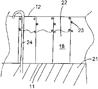
Figure 3 is a cross sectional view showing the mat laid over the
ground.
In the drawings like characters of reference indicate corresponding
parts in the different figures.
DETAILED DESCRIPTION
The mat described in general above is shown in Figure 1 and 2 and is
formed by a honeycomb core panel 10 having a first face 11 and a second
opposite
face 12 with an array of generally hexagonal tubular cells 18 defined by walls
I OA of
the core panel extending between the first and second faces. The cells are
formed
from a row of strips 15, 16 arranged side by side formed of a porous fibrous
material
which is heat sealed at a sealing line 14 to define the generally hexagonal
cells.
More particularly the strips of material 15, 16 etc arranged side by side
are connected at spaced positions 14, 14A longitudinally of the strips so that
each
strip 16 is connected to a next adjacent strip 15 on one side at first spaced
positions
14A and to a next adjacent strip 17 on an opposed side at second spaced
positions
14 which are arranged alternately to the first spaced positions 14A so as to
form a
honeycomb structure with top and bottom surfaces 11 and 12 of the mat defined
by
edges of the strips.
The cells are substantially empty and the mat is formed wholly by the

CA 02704301 2010-05-20
strips, that is, there is no top or bottom sheet closing the cells so that
they are open
to allow entry of material from top and bottom.
The strips are formed of a non-woven fibrous material such as a spun
bond fibrous plastics material so that the strips are porous.
5 The strips are connected together at connections 14 and 14A
preferably by heat bonding since this does not affect the properties of the
product at
the connection line and particularly leaves the product flexible and
compressible.
The mat so formed can be in the order of 4 feet to 8 feet wide with a
length which can be 30 feet or longer. The cells typically can have a diameter
(or
transverse dimension of the order of 2/8 inch to 6 inches and a depth, that
is, the
width of the strips which is typically 1/2 inch to 6 inches.
In use, the mat so formed is rolled into a roll 20 by compressing the
cells so that the strips 15, 16, 17 lie flat and compressed together. The mat
is
placed on ground 21 to be covered. Thus the mat is unrolled from the supply
roll 20
as shown in Figure 2 and laid around onto the ground. The mat is attached to
the
ground and laid out in the required rectangular shape by fastening pins 24 so
that
the rectangular strips of mat are laid side by side with side edges butting.
After laying, the cells are at least partly filled with top soil. The seeds
23 to generate growth over the covered ground are bonded to the cell walls or
are
impregnated into the cell walls.
Since various modifications can be made in my invention as herein
above described, and many apparently widely different embodiments of same made

CA 02704301 2010-05-20
6
within the spirit and scope of the claims without department from such spirit
and
scope, it is intended that all matter contained in the accompanying
specification shall
be interpreted as illustrative only and not in a limiting sense.

Representative Drawing
A single figure which represents the drawing illustrating the invention.
Administrative Status

2024-08-01:As part of the Next Generation Patents (NGP) transition, the Canadian Patents Database (CPD) now contains a more detailed Event History, which replicates the Event Log of our new back-office solution.

Please note that "Inactive:" events refers to events no longer in use in our new back-office solution.

For a clearer understanding of the status of the application/patent presented on this page, the site Disclaimer , as well as the definitions for Patent , Event History , Maintenance Fee  and Payment History  should be consulted.

Event History

Description Date
Application Not Reinstated by Deadline 2015-05-20
Time Limit for Reversal Expired 2015-05-20
Deemed Abandoned - Failure to Respond to Maintenance Fee Notice 2014-05-20
Inactive: Office letter 2011-12-01
Letter Sent 2011-12-01
Appointment of Agent Requirements Determined Compliant 2011-12-01
Revocation of Agent Requirements Determined Compliant 2011-12-01
Inactive: Office letter 2011-12-01
Appointment of Agent Request 2011-11-18
Revocation of Agent Request 2011-11-18
Application Published (Open to Public Inspection) 2010-12-22
Inactive: Cover page published 2010-12-21
Inactive: IPC assigned 2010-12-08
Inactive: IPC assigned 2010-07-07
Inactive: First IPC assigned 2010-07-07
Inactive: IPC assigned 2010-07-07
Application Received - Regular National 2010-06-16
Filing Requirements Determined Compliant 2010-06-16
Inactive: Filing certificate - No RFE (English) 2010-06-16
Small Entity Declaration Determined Compliant 2010-05-20

Abandonment History

Abandonment Date Reason Reinstatement Date
2014-05-20

Maintenance Fee

The last payment was received on 2013-05-13

Note : If the full payment has not been received on or before the date indicated, a further fee may be required which may be one of the following

  • the reinstatement fee;
  • the late payment fee; or
  • additional fee to reverse deemed expiry.

Please refer to the CIPO Patent Fees web page to see all current fee amounts.

Fee History

Fee Type Anniversary Year Due Date Paid Date
Application fee - small 2010-05-20
Registration of a document 2011-11-16
MF (application, 2nd anniv.) - small 02 2012-05-22 2012-05-04
MF (application, 3rd anniv.) - small 03 2013-05-21 2013-05-13
Owners on Record

Note: Records showing the ownership history in alphabetical order.

Current Owners on Record
RHINOKORE COMPOSITES MANUFACTURING PARTNERSHIP
Past Owners on Record
PAUL DAGESSE
Past Owners that do not appear in the "Owners on Record" listing will appear in other documentation within the application.
Documents

To view selected files, please enter reCAPTCHA code :


To view images, click a link in the Document Description column. To download the documents, select one or more checkboxes in the first column and then click the "Download Selected in PDF format (Zip Archive)" or the "Download Selected as Single PDF" button.

List of published and non-published patent-specific documents on the CPD .

If you have any difficulty accessing content, you can call the Client Service Centre at 1-866-997-1936 or send them an e-mail at CIPO Client Service Centre.


Document
Description 
Date
(yyyy-mm-dd) 
Number of pages   Size of Image (KB) 
Description 2010-05-20 6 178
Claims 2010-05-20 3 88
Drawings 2010-05-20 3 46
Abstract 2010-05-20 1 17
Representative drawing 2010-11-24 1 7
Cover Page 2010-11-30 2 38
Filing Certificate (English) 2010-06-16 1 156
Reminder of maintenance fee due 2012-01-23 1 113
Courtesy - Abandonment Letter (Maintenance Fee) 2014-07-15 1 171
Reminder - Request for Examination 2015-01-21 1 124
Correspondence 2010-06-16 1 58
Correspondence 2011-11-18 3 114
Correspondence 2011-12-01 1 13
Correspondence 2011-12-01 1 16