Note: Descriptions are shown in the official language in which they were submitted.
CA 02704393 2010-04-30
Tuning Peg
The invention relates to a tuning peg for a stringed musical instrument.
Strings of a stringed musical instrument are held on the peg box via pegs.
A tuning peg is a peg which makes tuning of a string possible.
Pegs are known from US 1,802,937, US 1,669,824, US 1,604,367,
DE 38 28 548 Al, US 1,506,373, US 5,998,713 or EP 1 453 034 A2.
The object underlying the invention is to provide a tuning peg which can be
fixed to a stringed musical instrument with a minimal effect on it and makes
simple tuning possible.
This object is accomplished in accordance with the invention, with the tuning
peg specified at the outset, in that a shank is provided which has a first
area
forming a string supporting area and at least one additional area which forms
a mounting area for fixing the tuning peg to the stringed musical instrument,
wherein the first area is rotatable relative to the at least one additional
area, a
first gear wheel which is connected non-rotatably to the first area is
provided,
at least one additional gear wheel which is connected non-rotatably to the at
least one additional area is provided, a head which is arranged on the shank
so as to be rotatable about an axis of rotation is provided and at least one
drive gear wheel which is arranged on the head and which acts on the first
gear wheel and the at least one additional gear wheel is provided.
With the solution according to the invention, a gear wheel gearing device is
provided which includes the first gear wheel, the at least one additional gear
wheel and the at least one drive gear wheel. As a result of a rotary movement
of the head, the at least one drive gear wheel can roll on the first gear
wheel
and the at least one additional gear wheel and thereby bring about a rotation
of the first area in relation to the at least one additional area. The tuning
peg
CA 02704393 2010-04-30
-2-
may be of a compact design as a result of the arrangement of the gear wheel
gearing device in the head.
As a result of a different number of teeth for the first gear wheel and the at
least one additional gear wheel or for the at least one drive gear wheel, a
transmission ratio may be set which allows tuning of the strings.
In addition, the gear wheel gearing device may be designed to be self-locking
in a simple manner. As a result, the torque which is exerted on the first area
on account of the tension of a string can be absorbed by the gearing device
and the first area is prevented from turning back. On the other hand, this
results in an optimized tuning capability with a simple operability.
The self-locking design may be achieved, for example, in that the first gear
wheel and the additional gear wheel are designed with pitch circles of
approximately the same size and the torque exerted on these gear wheels is in
opposite directions.
A high transmission ratio may be set as a result of at least two gear wheels
being used. For example, a transmission ratio of 7:1 or higher may be
achieved in a simple manner in order to be able to effect tuning.
Furthermore, the gear wheel gearing device may be designed such that, as
additional area, a second area and a third area are not rotatable relative to
one another. As a result, torque which is exerted on the stringed musical
instrument as peg torque as a result of the mounting of the tuning peg is kept
small. As a result, it is possible, on the other hand, to fix the tuning peg
to
the stringed musical instrument by way of press fitting without additional
connecting aids, such as adhesive and/or form locking elements, needing to be
provided.
CA 02704393 2010-04-30
-3-
It is particularly advantageous when the at least one drive gear wheel is
arranged at least partially in an interior space of the head. This results in
a
compact construction. The mechanism of the gear wheel gearing device for
rotation of the first area is also protected to the outside as a result.
The at least one drive gear wheel is favorably arranged so as to be offset in
relation to the axis of rotation of the head on the shank. As a result of such
an eccentric arrangement of the at least one drive gear wheel, the at least
one
drive gear wheel can be caused to move on an orbital path around the axis of
rotation when the head is rotated. As a result, it can roll on the first and
the
at least one additional gear wheel and cause them to rotate, whereby the first
area and the additional area are, on the other hand, rotated relative to one
another.
The at least one drive gear wheel is, in particular, rotatable about a drive
gear
wheel axis of rotation in order to enable it to roll on the first and the at
least
one additional gear wheel.
It is favorable when the at least one drive gear wheel axis of rotation is
oriented parallel to the axis of rotation of the head on the shank. This
results
in a simple constructional design and the dimensions of the head may be
minimized.
In one embodiment, the at least one drive gear wheel is a pinion or includes a
pinion. Such a pinion has, in particular, a smaller external diameter and a
smaller pitch circle diameter than the first gear wheel and the at least one
additional gear wheel. This results in a compact construction and the
dimensions of the head may be kept small. It is, in principle, also possible
for
CA 02704393 2010-04-30
-4-
the at least one drive gear wheel to be designed as a combination of several
gear wheels. Divided gear wheels can, in particular, be provided.
It is, in addition, favorable when the first gear wheel is positioned in an
interior space of the head. This results in a compact construction with a
simple production capability.
It is likewise favorable when the at least one additional gear wheel is
positioned in an interior space of the head. This results in a compact
construction.
It is particularly favorable when a gear wheel gearing device which includes
the first gear wheel, the at least one additional gear wheel and the at least
one drive gear wheel is positioned in an interior space of the head. As a
result, the shank can be designed in a simple manner and, in particular, the
diameter of the shank can be kept small and so adaptation to a musical
instrument is possible in a simple manner.
The first area and the at least one additional area follow one another on the
shank, in particular, in a longitudinal direction parallel to the axis of
rotation of
the head. This results in optimized dimensions.
It is, in principle, possible for a tuning peg to have only one mounting area
and one string supporting area. Such tuning pegs can be used, for example,
on plucked instruments, such as guitars, or also on zithers. In one
embodiment, a second area and a third area are provided and these form
respective mounting areas, wherein a second gear wheel is connected non-
rotatably to the second area and a third gear wheel is connected non-rotatably
to the third area. As a result, a relative rotatability of the first area not
only in
relation to the second area but also in relation to the third area may be
CA 02704393 2010-04-30
-5-
brought about, wherein the second area and the third area are not rotated
relative to one another. As a result, the torque which acts on a musical
instrument, to which such a tuning peg is fixed via the second area and the
third area, may be minimized.
The first area is then located, in particular, between the second area and the
third area, i.e., the string supporting area is located between two spaced
mounting areas. As a result, the tuning peg may be fixed to a peg box of a
musical instrument over a large mounting surface.
It is favorable when the second area, the first area and the third area follow
one another on the shank in a longitudinal direction parallel to the axis of
rotation of the head. As a result, the first area may be arranged between
mounting areas as a string supporting area.
The first area is favorably connected to a shaft, on which the first gear
wheel
is arranged. As a result, the first gear wheel may be positioned in spaced
relationship to the first area and, in particular, positioned in an interior
space
of the head.
The shaft is guided through the third area in order to make the connection
between the first gear wheel and the first area possible.
It is favorable when the shaft is rotatably mounted on an additional area. As
a
result, a rotary bearing for the rotatability of the first area relative to
the
additional area is made available.
The at least one additional gear wheel is favorably arranged coaxially to the
first gear wheel.
CA 02704393 2010-04-30
-6-
It is favorable, in addition, when the second gear wheel is arranged in an
interior space of the head in order to protect it and make a compact design
with a simple production capability possible.
It may be provided for the second gear wheel to be arranged on a pin element
which is guided through the first area and the third area. As a result, the
second gear wheel can be positioned on and, in particular, in the head in
spaced relationship to the second area. As a result, it is possible, on the
other
hand, to position the first gear wheel and the second gear wheel on the head
in immediate vicinity to one another and so the at least one pinion can act on
the first gear wheel and on the second gear wheel at the same time.
In this respect, it may be provided for the first pin element to be rotatably
mounted on the first area in order to make a relative rotatability between the
first area and the second area possible in a simple way.
For the same reason, it is favorable when the pin element is rotatably
mounted on a shaft, on which the first gear wheel is arranged.
It is particularly advantageous when the third area is connected non-rotatably
to the third gear wheel. As a result, a relative rotatability of the first
area
relative to the second area and the third area can be made possible in a
simple manner, wherein the second and the third areas are not rotated
relative to one another.
The third gear wheel is, in particular, arranged coaxially to the first gear
wheel
in order to make rotatability of the first area possible.
CA 02704393 2010-04-30
-7-
Furthermore, it is favorable when the at least one pinion acts on the third
gear
wheel in order to make rotatability of the first area relative to the third
area
possible.
In addition, it is favorable when the third gear wheel is arranged in an
interior
space of the head. As a result, it may be positioned at the operative area of
the at least one drive gear wheel and thereby be positioned in a protected
manner. This results in a compact construction with a simple production
capability.
It is favorable when the first gear wheel is arranged between the second gear
wheel which is connected non-rotatably to the second area and the third gear
wheel which is connected non-rotatably to the third area. This results in a
simple and compact construction. For example, the third gear wheel may be
formed in one piece with the third area.
It is particularly advantageous when the first gear wheel and the at least one
additional gear wheel have a different number of teeth and/or the at least one
drive gear wheel which acts on the first gear wheel and the second gear wheel
with a different number of teeth. As a result, a transmission may be achieved
which causes the first area to turn relative to the second area in a small
angular step in comparison with the rotation of the head on the shank. As a
result, tuning is possible. A transmission for the tuning may be achieved as a
result of a different "relative number of teeth" between the first gear wheel
and the at least one additional gear wheel. This different "relative number of
teeth" may be realized in that the first gear wheel and the second gear wheel
have a different number of teeth. Furthermore, it is possible to realize this
difference in that the at least one drive gear wheel acts on the first gear
wheel
and on the at least one additional gear wheel with a different number of
teeth.
This different number of teeth on the at least one drive gear wheel may be
CA 02704393 2010-04-30
-8-
realized, for example, in that it is designed in several parts with a first
gear
subwheel with acts on the first gear wheel and with a second gear subwheel
which acts on the at least one additional gear wheel, wherein the first gear
subwheel and the second gear subwheel have a different number of teeth. It
is also possible for a combination consisting of at least two drive gear
wheels
to be used, wherein gear wheels with different numbers of teeth are provided
in this combination. The two possibilities can also be combined, i.e., not
only
the first gear wheel but also the at least one additional gear wheel have a
different number of teeth and also the at least one drive gear wheel acts on
the first gear wheel and on the at least one additional gear wheel with a
different number of teeth.
In one embodiment, the first gear wheel has a greater number of teeth than
the at least one additional gear wheel. When the first gear wheel has a
smaller number of teeth, the first area turns in an opposite direction during
rotation of the head about the shank. With a greater number of teeth, the
first area turns in the same direction with the rotation of the head about the
shank. This makes tuning easier for a user.
It is particularly advantageous when the second gear wheel which is connected
non-rotatably to the second area and the third gear wheel which is connected
non-rotatably to the third area have the same number of teeth. As a result, it
is possible in a simple manner for the second gear wheel and the third gear
wheel not to rotate relative to one another during rolling movement of the at
least one pinion on these gear wheels. As a result, the wear and tear on a peg
box can be kept small; the second area and the third area are seated in the
bow in the peg box and act, in principle, on it. When they are not turned
relative to one another, the torque exerted is also minimized. As a result, it
is
also possible, on the other hand, to fix the corresponding tuning peg to the
peg box simply by way of press fitting.
CA 02704393 2010-04-30
-9-
It is particularly advantageous when the first gear wheel has a different
number of teeth in comparison with the second gear wheel and/or the third
gear wheel. As a result, a defined transmission ratio may be achieved which
is greater than one. As a result, it is, for example, possible, on the other
hand, to alter string lengths in the order of magnitude of 0.01 mm or less
when the transmission ratio is set accordingly. This results in great
precision
during tuning.
The number of teeth of the first gear wheel and/or the number of teeth, with
which the at least one drive gear wheel acts on the first gear wheel,
advantageously differs by m + i from the number of teeth of the at least one
additional gear wheel and/or the number of teeth, with which the at least one
drive gear wheel acts on the at least one additional gear wheel, wherein m is
a
natural number and i is the number of drive gear wheels which act on the first
gear wheel and the at least one additional gear wheel and which are spaced
transversely to the axis of rotation. This results in a gearing device, the
transmission ratio of which (greater than one) may be set accordingly and
which is self-locking. As a result of the at least one drive gear wheel
rolling on
the first gear wheel, a second gear wheel and, where applicable, a third gear
wheel, the first area is turned in accordance with the transmission ratio set.
As a result of rotation of the head relative to the shank, the at least one
drive
gear wheel rolls on the gear wheels.
The at least one drive gear wheel is favorably of a height which is at least
as
great as the overall height of a combination consisting of first gear wheel
and
at least one additional gear wheel. As a result, the at least one drive gear
wheel can roll simultaneously on the first gear wheel and the at least one
additional gear wheel and, as a result, make a relative movement of the first
area in relation to the at least one additional area possible.
CA 02704393 2010-04-30
-10-
It is favorable when a plurality of drive gear wheels are present which are
arranged so as to be evenly distributed on the head in relation to the axis of
rotation of the head on the shank. As a result, it may be ensured that at
least
two teeth of the drive gear wheels always engage in the gear wheels which are
associated with the first area and the at least one additional area. This
results
in a uniform rotary movement of the first area in order to make an optimized
tuning possible. In principle, more than two drive gear wheels may be
present; the more drive gear wheels, the more uniform the rotary movement.
However, the space requirements are also greater as a result. When i drive
gear wheels are present, their axes of rotation should be arranged so as to be
spaced through an angle of 360 /i in relation to the axis of rotation of the
head on the shank. In one advantageous embodiment, two drive gear wheels
are present; as a result, an optimized compromise is achieved between space
requirements in the head and homogeneity of the rotary movement of the first
area.
In one embodiment, an end of the tuning peg facing away from the head is
formed on the at least one additional area. The at least one additional area
is
an outer area and, as a result, can also, in principle, be machined.
The at least one additional area advantageously has an area which can be cut
to length. As a result, the length of the tuning peg can be adapted to a
stringed musical instrument. The area of a tuning peg which projects beyond
the peg box can, in particular, be shortened.
In an alternative embodiment, an end of the tuning peg facing away from the
head is formed on the first area. A string supporting area forms, as a result,
an end area of the tuning peg.
CA 02704393 2010-04-30
-11-
It is particularly advantageous when a gear wheel gearing device for the
rotation of the first area about the first gear wheel by means of the at least
one pinion is designed to be self-locking. A tensioned string which is held at
the first area exerts torque on the first area, in principle, via the
tensioning;
this can cause a backward rotation. As a result of a self-locking design of
the
gear wheel gearing device, this is prevented. As a result, an optimized tuning
can, on the other hand, be achieved.
A self-locking gear wheel gearing device may be realized in a simple manner
when the first gear wheel and the at least one additional gear wheel have at
least approximately the same pitch circle diameter. When, for example,
diametrically spaced pinions are present as drive gear wheels, the torque may
be applied to the first gear wheel and the at least one additional gear wheel
in
opposite directions. As a result, the torques applied to the pinions cancel
one
another out.
The at least one drive gear wheel favorably moves orbitally about the axis of
rotation of the head on the shank as a result of rotation of the head. As a
result, the at least one drive gear wheel can roll on the first gear wheel and
the at least one additional gear wheel (and, where applicable, on a second
gear wheel and third gear wheel) in order to cause the first area to rotate.
It is favorable when the at least one drive gear wheel rolls on the first gear
wheel and the at least one additional gear wheel (where applicable, a second
gear wheel and third gear wheel) as a result of rotation of the head. As a
result, rotation of the first area can be brought about in a simple manner,
wherein this rotation is initiated by rotation of the head. By providing a
second gear wheel and third gear wheel which are connected non-rotatably to
a second area and to a third area, respectively, a transmission ratio may be
set which brings about a slower rotation of the first area.
CA 02704393 2010-04-30
- 12-
The head favorably has at least one finger gripping surface for the easy
operability of the rotary movement relative to the shank.
The following description of preferred embodiments serves to explain the
invention in greater detail in conjunction with the drawings. These show:
Figure 1 a side view of a violin as example of a stringed musical
instrument;
Figure 2 a schematic illustration of a peg box of a stringed musical
instrument, on which tuning pegs are arranged;
Figure 3 a sectional view of one embodiment of a tuning peg
according to the invention;
Figure 4 an enlarged illustration of a head of the tuning peg
according to Figure 3;
Figure 5 a sectional view along line 5-5 according to Figure 4;
Figure 6 a perspective exploded illustration of the tuning peg
according to Figure 3 with a head in a sectional view;
Figure 7 a perspective exploded illustration of a second
embodiment of a tuning peg according to the invention;
Figure 8 a partial sectional illustration of the tuning peg according
to Figure 7; and
CA 02704393 2010-04-30
-13-
Figure 9 a perspective exploded illustration of a third embodiment
of a tuning peg according to the invention with a partial
sectional view of a shank.
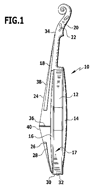
A violin 10 as example of a (bowed) stringed musical instrument has, as
shown in Figure 1, a rib 12 with a back 14 and a top 16 which form a body 17.
A fingerboard 18 is arranged on the rib 12 and a peg box 20 is seated on the
fingerboard. The peg box 20 is produced from wood, such as, for example,
maple. Pegs 22, via which strings 24 may be fixed to the peg box 20 at one
end of the string, are arranged on the peg box 20.
At their other end 26, the strings 24 are fixed to a tailpiece 28. This
tailpiece
28 has a tail gut 30 which forms a tail gut bow. The tail gut bow is attached
to an end button 32 in order to hold the tailpiece 28 in place.
If the end 26 of a string 24 is secured via the tailpiece 28 relative to the
rib
12, the tension on the string 24 may be altered via the associated peg 22 and
the string may be tuned, as a result.
That part of the string 24 which is located between a nut 34 on the
fingerboard 18 and a bridge 36 arranged on the top 16 is designated as
primary string 38. That part of the string 24 which is located between the
bridge 36 and the tailpiece 28 is designated as secondary string 40.
The peg box 20 includes a first strip 42 consisting of wood and a second strip
44 of wood spaced therefrom. The strings 24 of the stringed musical
instrument 10 are guided between the first strip 42 and the second strip 44.
In order to fix a peg 22 in place, corresponding bores 46 are arranged in the
first strip 42 and bores 48 in the second strip 44. A pair of bores consisting
of
CA 02704393 2010-04-30
-14-
a first bore 46 and a second bore 48 oriented in alignment therewith is
associated with the peg 22.
The first bores 46 and the second bores 48 are respectively designed to be
rotationally symmetric; the corresponding axes of symmetry of the associated
bores of one pair are coaxial with their axis of symmetry. The diameter of the
bores 46 and 48 can be adapted to the diameter of a shank 50 of a peg 22
with a peg reamer.
A peg 22 has a first mounting area 52, with which it is held on the first
strip
42, and a second mounting area 54 which is spaced thereto and with which it
is held on the second strip 44. A string supporting area 56 which supports a
string 24 is arranged between the first mounting area 52 and the second
mounting area 54.
One end 60 of the shank and of the peg 22 is located opposite the head 58.
A peg according to the invention is designed as a tuning peg. One
embodiment is shown in Figure 3 and designated as 62.
The shank 50 of the tuning peg 62 includes a first area 64 which is designed
as a string supporting area 56. It further includes a second area 66 which is
designed as a second mounting area 54 and a third area 68 which is designed
as a first mounting area 52.
The second area 66, the first area 64 and the third area 68 follow one another
in a linear manner. They are essentially designed to be rotationally symmetric
to an axis 70 and are coaxial to this axis 70. The end 60 is formed on the
second area 66.
CA 02704393 2010-04-30
-15-
The second area 66 is produced from a solid material, at least in one section
72. This solid material is, for example, a metallic material, such as
aluminum,
a plastic material or a wood material. A pin element 74 which extends along
the axis 70 is held non-rotatably at the second area 66. The pin element 74 is
held on the second area 66 via a form locking connection 76 or a press fitting
connection.
The second area is, for example, of a truncated design at least in one
section.
The second area 66 can be shortened outside the connection area to the pin
element 74. This is indicated in Figure 3 by a cutting plane 78. As a result,
the tuning peg 62 may be adapted to the peg box 20 of a stringed musical
instrument 10; the area of the tuning peg 22 projecting beyond the second
strip 44 can be shortened. The length of the tuning peg 62 can, as a result,
be adapted individually to a stringed musical instrument.
The pin element 74 is produced, for example, from a metallic material, such
as, for example, aluminum, steel, brass etc. It is guided through an interior
space 80 of the first area. Furthermore, it is guided through an interior
space
82 of the third area 68.
The first area 64, which follows the second area 66, is produced, for example,
from a metallic material, such as, for example, aluminum, steel, brass etc. It
has one or more insertion holes 84 for a string 24. The first area 64 is
rotatable about an axis of rotation 86 relative to the second area 66. The
axis
of rotation 86 coincides with the axis 70.
The first area 64 is also designated as a spool since an end area of a string
24
can be wound onto it in a spool-like manner.
CA 02704393 2010-04-30
-16-
A shaft 88 is held non-rotatably at the first area 64. The shaft 88 can, in
this
respect, be connected to the first area 64 in one piece or it can be fixed to
it
afterwards. The shaft 88 is guided through the interior space 82 of the third
area 68. The first area 64 is rotatable about the axis of rotation 86 relative
to
the third area 68. The first area 64 is rotatably mounted on the third area 68
via the shaft 88.
The shaft 88 has an interior space 90, through which the pin element 74,
which is connected non-rotatably to the second area 66, is guided.
A first gear wheel 92 is seated non-rotatably on the shaft 88 at or in the
vicinity of an end facing away from the first area 64. This gear wheel is, as
a
result, connected to the first area 64 non-rotatably and spaced in relation to
it
(via the shaft 88). The first gear wheel 92 is arranged coaxially to the axis
of
rotation 86.
The first gear wheel 92 is produced, for example, from a metallic material,
such as aluminum or stainless steel.
The first gear wheel 92 has a number nl of teeth distributed uniformly around
the axis of rotation 86.
A second gear wheel 94 is seated on the pin element 74 at or in the vicinity
of
an end facing away from the second area 66. The second gear wheel 94 is
connected non-rotatably to the pin element 74 and is, as a result, connected
non-rotatably to the second area 66 and spaced in relation to it (via the pin
element 74).
The second gear wheel 94 is arranged coaxially to the axis of rotation 86. It
has a number n2 of teeth distributed uniformly around the axis of rotation 86.
CA 02704393 2010-04-30
- 17-
The external diameter of the first gear wheel 92 and the external diameter of
the second gear wheel 94 are essentially the same. The first gear wheel 92
and the second gear wheel 94 are adjacent to one another. In this respect, a
small distance may lie between them or they can abut on one another,
wherein a relative rotation of the first gear wheel 92 and the second gear
wheel 94 is made possible. For example, the second gear wheel 94 is an outer
gear wheel which is at a greater distance to the end 60 in comparison with the
first gear wheel 92.
A third gear wheel 96 is seated non-rotatably on the third area 68. This third
gear wheel 96 is positioned in a region of the third area 68 which is located
at
or in the vicinity of an end which faces away from the end which points
towards the first area 64. The third gear wheel 96 can be formed in one piece
on the third area 68 or it can be a separate element which is positioned on
the
third area 68 afterwards.
The third area 68 is of a truncated design, at least in one section.
The third gear wheel 96 is coaxial to the axis of rotation 86. It has a number
n3 of teeth distributed uniformly around the axis of rotation 86. The third
gear
wheel 96 follows the first gear wheel 92, i.e., the third gear wheel 96 is
that
gear wheel which is located closest to the end 60 in the series of gear wheels
92, 94, 96.
The gear wheel 96 has essentially the same external diameter as the first gear
wheel 92 and the second gear wheel 94. The gear wheels 92, 94, 96 are
designed, for example, as spur gears.
CA 02704393 2010-04-30
- 18-
The head 58 is arranged on the shank 50 for rotation about an axis of rotation
98. The axis of rotation 98 coincides with the axis of rotation 86 of the gear
wheels 92, 94, 96. The head 58 is also designated as a knob.
The head 58 has a gripping part 100, via which a user can bring about
rotation. The gripping part 100 is designed, for example, so as to be in
mirror
symmetry to a plane which is parallel to the plane of drawing of Figure 3. It
has a first width bl in a first direction at right angles to the axis of
rotation 98
and a second width b2 in a direction at right angles thereto and to the axis
of
rotation 98 (Figures 3, 7). The width b2 is smaller than the width bl. The
gripping part 100 is designed, for example, in the shape of a mushroom with
finger gripping surfaces 102 on opposite sides.
The gripping part 100 and, with it, the head 58 has an interior space 104, in
which a gear wheel gearing device 106 is arranged, via which a rotary
movement of the head 58 can be transferred to the first area 64 of the shank
50. The gear wheels 92, 94, 96 are part of this gear wheel gearing device
106.
The gripping part 100 has a central opening 108 which is located coaxially
around the axis of rotation 98. An externally threaded element 110 is seated
non-rotatably on the shank 50. This element is arranged coaxially to the axis
70. The externally threaded element 110 engages in the opening 108 of the
gripping part 100. A pin 112 with an internal thread 114 is screwed onto the
externally threaded element 110. The pin 112 has a head 116 which, when
the pin 112 is screwed in, abuts on a base 118 of a recess 120 in the gripping
part 100. The recess 120 thereby forms an enlargement of the opening 108
towards an upper side of the gripping part 100. Any axial lifting of the head
58 away from the third area 68 of the shank 50 is blocked via the head 116.
CA 02704393 2010-04-30
- 19-
The head 58 has, in addition, a contact area 122 which faces the third area 68
of the shank 50 and is, for example, of an annular design. This contact area
122 forms a blocking surface for the movement of the head 58 towards the
third area 68.
The pin 112 has a cylindrical area 124 which forms a rotary bearing pin
(external shaft) for the rotatability of the head 58 relative to the shank 50.
A first pinion 126 and a second pinion 128 are arranged in the interior space
104 of the head 58 as drive gear wheels. These drive gear wheels 126, 128
are designed, for example, as spur gears. They are rotatable about a first
drive gear wheel axis of rotation 130 and about a second drive gear wheel axis
of rotation 132, respectively. The drive gear wheel axes of rotation 130 and
132 are located parallel to the axis of rotation 98 of the head 58 relative to
the
shank 50 and are respectively offset to it, i.e., are in spaced parallel
relationship to it. The first pinion 126 (first drive gear wheel 126) and the
second pinion 128 (second drive gear wheel 128) are, as a result, arranged
eccentrically to the rotary mounting of the head 58 in the shank 50.
The rotatability of the first pinion 126 and the second pinion 128 is
respectively realized by a pin 134 which is, in particular, of a cylindrical
design
and is formed in a cylindrical recess 136 in the interior space 104 of the
head
58. The respective pin 134 of the first pinion 126 and the second pinion 128
is
connected non-rotatably to it.
The first pinion 126 and the second pinion 128 are located opposite one
another in a width direction at right angles to the axis 70, each with the
same
distance to the axis of rotation 98; they are, as a result, arranged so as to
be
distributed uniformly around the axis of rotation 98.
CA 02704393 2010-04-30
-20-
The series of gear wheels with the first gear wheel 92, the second gear wheel
94 and the third gear wheel 96 is located between the first pinion 126 and the
second pinion 128. Both the first pinion 126 and the second pinion 128
engage in the gear wheels 92, 94, 96. The pinions 126 and 128 are part of
the gear wheel gearing device 106.
The first pinion 126 and the second pinion 128 are caused to move orbitally
around the axis of rotation 98 as a result of a rotary movement of the head 58
about the axis of rotation 98 relative to the shank 50. The first pinion 126
and
the second pinion 128 roll on the first gear wheel 92, the second gear wheel
94 and the third gear wheel 96 and cause them to move in a corresponding
rotary movement, as will be explained below in greater detail. As a result of
the gear wheel gearing device 106, the rotary movement is transferred to the
first area 64 in order to be able to bring about tuning of a string 24.
The number of teeth n2 of the second gear wheel 94 and the number of teeth
n3 of the third gear wheel 96 is the same (n2 = n3). The number of teeth of
the first gear wheel 92 differs therefrom, i.e., nl # n2, n3. The number of
teeth nl of the first gear wheel 94 can, in this respect, be greater than or
smaller than n2, n3. When the number of teeth nl is greater than n2, n3, the
direction of rotation of the head 58 about the axis of rotation 98 and the
direction of rotation of the first area 64 about the axis of rotation 96 are
the
same. When the number of teeth nl is smaller than n2, n3, the direction of
rotation of the head 58 relative to the shank 50 and the direction of rotation
of
the first area 64 about the axis of rotation 86 are opposite to one another.
The transmission of the gear wheel gearing device 106 is determined by the
number of teeth. This results as
CA 02704393 2010-04-30
-21-
n' 1 (1)
n, - nz
In one embodiment, nl is 17 and n2, n3 are 15. The transmission then results
as 8.5 : 1, i.e., with 8.5 revolutions of the head 58 about the shank 50, the
first area 64 rotates once (through 3600) about the axis of rotation 86.
In the case of the embodiment described above, the gear wheel gearing
device 106 includes two pinions as drive gear wheels, namely the first pinion
126 and the second pinion 128. The pinions 126 and 128 have, in particular,
a smaller (external) diameter than the gear wheels 92, 94, 96 and also a
smaller pitch circle diameter than them.
It is also possible for only one pinion to be provided as drive gear wheel or
for
more than two pinions to be provided. When i pinions, which are arranged
with their axes of rotation so as to be offset in relation to the axis of
rotation
98, are present, the number of teeth of the first gear wheel 92 must differ by
m + i from the number of teeth n2, n3, wherein m is a natural number. In the
case where two pinions (i = 2) are present, the first gear wheel 92 must,
therefore, have 2, 4, 6 etc. more teeth or correspondingly less teeth than the
second gear wheel 94 and the third gear wheel 96.
It is, in principle, also possible for the pinions to act only on the first
gear
wheel 92 in order to rotate the first area 64 and for the second gear wheel 94
and the third gear wheel 96 to not be present.
As a result of the solution according to the invention, the tuning of a string
24
is possible as a result of rotation of the head 58 relative to the shank 50,
this
string being held on the first area 64 (string supporting area 56). The shank
50 does not rotate outside the first area 64 and so no wear and tear on the
CA 02704393 2010-04-30
- 22-
bores 46 and 48 in the peg box 20 as a result of rotation of the head 58
relative to the shank 50 occurs.
It has been shown that as a result of the solution according to the invention
string lengths may be altered in steps of 0.01 mm or less. This results in
great precision during tuning. When, for example, the gear wheel gearing
device 106 has a transmission ratio of 8.5 : 1, a change in the string length
of
2.59 mm during a full rotation through 3600 results with a diameter of the
first
area 64 of 7 mm which is a typical diameter (with a resulting string length of
22 mm at the first area 64). The rotatability can be metered in steps of
approximately 10 and so the above-mentioned tuning capability of length
changes of approximately 0.01 mm per string 24 results.
The gear wheel gearing device 106 is designed to be self-locking. The string
24 exerts torque on the first area 64 on account of the string tension. As a
result of the self-locking design of the gear wheel gearing device 106, the
set
rotary position of the first area 64 is maintained, i.e., the string 24 cannot
turn
the first area 64 back. The shank 50 with its mounting areas 52, 54 need not
make any contribution to the "braking" of the return rotation of the first
area
64. As a result, it is possible, on the other hand, to press the shank 50 with
the second area 66 and 68 securely into the bores 46 and 48 and fix it in
place
in this manner without any additional fixing being necessary apart from the
press fitting. In particular, no additional adhesion or any additional form
locking need be provided. As a result, the action on the stringed musical
instrument for fixing the tuning peg 62 in place is minimized.
The gear wheels 92, 94, 96 have at least approximately the same pitch circle
diameter (working diameter). The torques exerted on the respective gear
wheels 92, 94, 96 are in opposite directions. As a result of the pitch circle
diameters of these gear wheels 92, 94, 96 which are at least approximately of
CA 02704393 2010-04-30
-23-
the same size, the torques acting on the pinions 126, 128 cancel each other
out and the gear wheel gearing device 106 is self-locking.
As already mentioned above, a projecting end of the tuning peg 62 can be
shortened in a simple manner by cutting to length (shortening the second area
66) and, therefore, be adapted to the peg box 20.
As likewise mentioned above, it is, in principle, possible for the gear wheel
gearing device 106 to include only one pinion. When more than one pinion is
present, several pinion teeth can be in engagement and the load can be
distributed over at least two teeth. As a result, a more even transfer of the
rotary movement of the head 58 to the second area 64 can be achieved.
When several pinions are present, they should be arranged so as to be
uniformly distributed in relation to the axis of rotation 98.
The provision of two pinions 126, 128 is ideal to the extent that the space
requirements in the head 58 can be kept small; when more than two pinions
are present, the head 58 must be of a correspondingly larger design.
The tuning peg 62 according to the invention may, in principle, be used with
all types of stringed musical instruments and, in particular, with bowed
string
instruments and plucked instruments when the dimensions are adapted
accordingly.
As a result of the fact that the second gear wheel 94 and the third gear wheel
96 have the same number of teeth and the first gear wheel 92 has a number
of teeth differing therefrom, no relative rotation occurs between the second
area 66 and the third area 68; the first area 64 is, however, rotatable
relative
to the second area 66 and is rotatable relative to the third area 68. As a
result, the second area 66 and the third area 68 experience a minimized
CA 02704393 2010-04-30
-24-
torque when they are arranged in the respective bores 48, 46 in the peg box
20.
Combinations of several gear wheels can also be used as drive gear wheels for
driving the gear wheels 92, 94, 96.
It is, in principle, possible alternatively or in addition for a drive gear
wheel to
act on the first gear wheel 92 and the second gear 94 or the third gear wheel
96 with a different number of teeth. In this case, the gear wheels 92 and 94
or 92 and 96 have the same number of teeth since the transmission is
provided by the different number of teeth of the corresponding drive gear
wheel (pinion).
For this purpose, the drive gear wheel is, for example, designed such that it
has different sections with different numbers of teeth in the direction of the
axis of rotation 98. Each section rolls, in this respect, on a respective gear
wheel 92, 94 and 96.
It is also possible for a series of drive gear wheels, which are connected non-
rotatably to one another and which have different numbers of teeth, to be
used instead of one drive gear wheel. In particular, that drive gear wheel in
the series which engages the first gear wheel 92 has a different number of
teeth to the additional drive gear wheels in the series which engage the
second gear wheel 94 and the third gear wheel 96.
A transmission for the purpose of tuning may be brought about when a
difference in the "relative number of teeth" for the first gear wheel 92 in
comparison with the second gear wheel 94 and the third gear wheel 96 is
present. This difference in the "relative number of teeth" may be brought
about by different numbers of teeth between the first gear wheel 92 and the
CA 02704393 2010-04-30
- 25 -
second gear wheel 94 or the third gear wheel 96 and/or by a different number
of teeth on that part of a drive gear wheel or series of drive gear wheels
which
acts on the first gear wheel 92 and the second gear wheel 94 or the third gear
wheel 96.
A second embodiment of a tuning peg according to the invention, which is
shown in Figures 7 and 8 and designated in this case as 138, includes a shank
140 with a first area 142 which is a string supporting area and a second area
144 which is a mounting area. A front end 146 of the tuning peg 138 is
formed on the first area 142. A ring element 148 is arranged at the first area
142 in the region of the end 146 and this protrudes beyond a surface 150 of
the first area 142. This ring element 148 serves to prevent an area of a
string
held on the string supporting area 142 from slipping off.
The ring element 148 is formed, for example, via a disk element which is
arranged at the end of the shank 140.
The second area 144 has, for example, a conically extending surface 152.
A shaft 156 is guided through an interior space 154 of the second area 144
and is connected non-rotatably to the first area 142. The shaft 156 is of a
cylindrical design. The interior space 154 is of a hollow cylindrical design.
The
shaft 156 is mounted in the interior space 154 for rotation about an axis of
rotation 158.
A first gear wheel 160 is seated non-rotatably on the shaft 156 above the
second area 144. The first gear wheel 160 is positioned coaxially to the axis
of rotation 158.
CA 02704393 2010-04-30
-26-
A second gear wheel 162 is seated on the second area 144 directly beneath
the first gear wheel 160. The second gear wheel 162 is arranged so as to be
rotatable about the axis of rotation 158 and coaxial to the first gear wheel
160.
The second gear wheel 162 is, for example, formed in one piece on the second
area 144.
A head is positioned for rotation on the shaft 156. This head is, in
principle, of
the same design as the head 58 of the tuning peg 62. For this reason, the
same reference numeral is used.
A pin element 164 with an external thread 166 is seated on the shaft 156
above the first gear wheel 160 and is aligned coaxially to the axis of
rotation
158. A pin corresponding to the pin 112 with a cylindrical area 124 is screwed
onto this external thread. The head 158 is rotatable about this pin 112 which
forms an external shaft.
A first pinion 168 and a second pinion 170 are seated in the interior space
104
of the head 58 as drive gear wheels. The pinions 168, 170 have the same
function as the pinions 126 and 128 of the tuning peg 62. They can move
orbitally as a result of rotation of the head 58. They act on the first gear
wheel 160 and the second gear wheel 162.
The first gear wheel 160 is designed, in particular, as a spur gear. It has a
number of teeth n1. The second gear wheel 162 is likewise preferably
designed as a spur gear. It has a number of teeth n2. In this respect, the
number of teeth nl of the first gear wheel 160 is greater than the number of
teeth n2 of the second gear wheel 162. During rotation of the head 58, the
first gear wheel 160 and the second gear wheel 162 are caused to rotate by
CA 02704393 2010-04-30
-27-
the pinions 168 and 170, wherein a relative rotation to one another occurs.
The transmission ratio results in accordance with equation (1) above.
The gear wheel gearing device, which is formed by the gear wheels 160, 162
and by the pinions 168 and 170 and is positioned in the interior space 104 of
the head 58, is self-locking.
The first area 142 as spool supporting area is rotatable relative to the
second
area 144 via rotation of the head 58 with a transmission ratio in accordance
with equation (1).
The tuning peg 138 is particularly suitable for plucking instruments, such as
guitars.
A third embodiment of a tuning peg, which is shown in Figure 9 and
designated in this case as 172, includes a shank 174. This has a first area
176
which is a string supporting area. This first area 176 is followed by a second
area 178 which is a mounting area for fixing to a musical instrument. The
second area 178 has an end 180 which is a front end of the tuning peg 172.
A shaft 182 is non-rotatably seated on the second area 178. It is guided
through an interior space 184 of the first area 176.
The first area 176 has a surface 186 which is a winding area for a string.
A first gear wheel 188 is, for example, arranged in one piece on the first
area
176. A second gear wheel 190 is seated above this first gear wheel 188,
connected non-rotatably to the shaft 182 and, therefore, non-rotatably to the
second area 178. The first gear wheel 188 has a number of teeth nl and the
CA 02704393 2010-04-30
-28-
second gear wheel 190 has a number of teeth n2. The number of teeth nl
differs from the number of teeth n2.
Pinions 192, 194 act on the gear wheels 188 and 190. They move orbitally
around an axis of rotation 196. A relative rotation of the first area 176 and
the second area 178 relative to one another takes place with the transmission
ratio specified in the above equation (1).
A head is, in principle, of the same design as that described in conjunction
with the first embodiment 62 and the second embodiment 138. The same
reference numerals are, therefore, used.
The second area 178 can, in principle, be cut to length.
Otherwise, the tuning peg 172 functions as described above in conjunction
with the tuning pegs 62 and 138.
The tuning peg 172, with which the string supporting area 176 is arranged
between the head 58 and the mounting area 178, may be used, for example,
for a zither.
The tuning peg 62 has two mounting areas, namely the mounting areas 66
and 68, between which the first area 64 is arranged as string supporting area.
The tuning pegs 138 and 172 have only one mounting area, namely the
second area 144 and 178, respectively. In the case of the tuning peg 138,
this mounting area 144 is arranged between the head 58 and the first area
142. In the case of the tuning peg 172, the string supporting area 176 is
arranged between the head 58 and the mounting area 178.