Note: Descriptions are shown in the official language in which they were submitted.
CA 02704443 2010-05-14
SLANTED RETAIL SHIPPER DISPLAY
Cross-Reference to Related Application
[00011 This application claims the benefit of U.S. Provisional Application No.
61/216,168, which was
filed on May 14, 2009.
Incorporation by Reference
100021 U.S. Provisional Application No. 61/216,168, which was filed on May 14,
2009, is hereby
incorporated by reference for all purposes as if presented herein in its
entirety.
Background
100031 Packaging materials such as cartons are useful for holding and
transporting articles. Some
cartons are useful as containers to hold other articles, including other
cartons, for example, for
use on a retailer's shelf or shelving. In order to facilitate dispensing of
articles from a carton, it
generally is beneficial to form a dispenser with a portion of the carton.
Summary
100041 The present disclosure generally relates to blanks, packages, or
cartons for holding and/or
dispensing products such as, for example, bottles, cans, rolls, or other
containers or articles.
[00051 In one aspect, the present invention includes a carton including an
upper portion and a lower
portion separated by at least one tear line. The carton includes a back panel
and a bottom panel.
The back panel is foldably connected along a first fold line to a first
accordion panel, and a
second accordion panel is foldably connected along a second fold line to the
first accordion
panel. The back panel, the first accordion panel, and the second accordion
panel are movable
between a first position and a second position. In the first position, the
first accordion panel and
the second accordion panel are oriented or arranged substantially parallel to
the back panel and
CA 02704443 2010-05-14
are substantially perpendicular to the bottom panel. In the second position,
the back panel is
moved toward the bottom panel, the second accordion panel is disposed
substantially parallel the
bottom panel, and the first accordion panel is disposed generally at a
diagonal or an angle
defined between the second fold line and the back panel.
[00061 The at least one tear line of the carton can include a first tear line
and a second tear line that each
can extend around approximately half of the carton. The ends of the first tear
line and the second
tear line generally meet adjacent one another to form a substantially
continuous tear line around
the carton. The upper portion of the carton is removable from the lower
portion by separating
along the first tear line and the second tear line. A flap also can be
provided above the back
panel.
[00071 In another aspect, the present invention includes a package comprising
a plurality of articles and
a carton for containing and/or dispensing such articles. The carton generally
comprises an upper
portion and a lower portion separated by at least one tear line. The carton
includes at least a back
panel and a bottom panel, with the back panel having two accordion panels at a
lower portion of
the back panel. The back panel is foldably connected along a first fold line
to a first accordion
panel of the two accordion panels, and a second accordion panel is foldably
connected along a
second fold line to the first accordion panel. The back panel, the first
accordion panel, and the
second accordion panel are movable between a first position and a second
position. In the first
position, the first accordion panel and the second accordion panel are
substantially parallel to the
back panel and are substantially perpendicular to the bottom panel. In the
second position, the
back panel is moved downward in a direction toward the bottom panel, the
second accordion
panel is disposed substantially parallel the bottom panel, and the first
accordion panel generally
is disposed at a diagonal or an angle defined between the second fold line and
the back panel.
2
CA 02704443 2010-05-14
[00081 The at least one tear line of the package can include a first tear line
and a second tear line that
each can extend around approximately half of the carton. The ends of the first
tear line and the
second tear line generally meet adjacent one another to form a substantially
continuous tear line
around the carton. The upper portion generally is removable from the lower
portion by
separating along the first tear line and the second tear line. A flap extends
above the back panel.
When the back panel is moved to the second position, the articles in the
carton are slanted toward
the back panel.
[00091 In another aspect, the present invention includes a blank comprising a
first panel that is
connected to a second panel along a first fold line, the second panel is
connected to a third panel
along a second fold line, the third panel is connected to a fourth panel along
a third fold line, the
fourth panel is connected to a first accordion panel along a fourth fold line,
and the first
accordion panel is connected to a second accordion panel along a fifth fold
line. A first end flap
is connected along a sixth fold line to the second panel at a first end of the
blank. A second end
flap is connected along a seventh fold line to the second panel at a second
end of the blank. A
third end flap is connected along an eighth fold line to the fourth panel at
the first end of the
blank. A fourth end flap is connected along a ninth fold line to the fourth
panel at the second end
of the blank. A first tear line extends across the first end flap, the second
panel, and the second
end flap. A second tear line extends across the third end flap, the fourth
panel, and the fourth
end flap. The first end flap, the second end flap, the third end flap, and the
fourth end flap each
include at least one angled edge that allow the fourth panel to move toward
the first accordion
panel and the second accordion panel when the blank is formed into a carton.
[0010] An opening assisting device can be included along the first tear line
and along the second tear
line. The opening assisting device can be an opening, a finger flap, or
similar opening feature.
3
CA 02704443 2010-05-14
In order to form the blank into a carton, the first and third end flaps
overlap and the second and
fourth end flaps overlap.
[00111 In another aspect, a method of slanting articles in a package is
provided. The package comprises
a plurality of articles and a carton for storing and dispensing the articles.
The method includes
providing the carton including an upper portion and a lower portion separated
by at least one tear
line, and at least a back panel and a bottom panel. The back panel has two
accordion panels at a
lower portion. The back panel is foldably connected along a first fold line to
a first accordion
panel of the two accordion panels. A second accordion panel is foldably
connected along a
second fold line to the first accordion panel. The back panel, the first
accordion panel, and the
second accordion panel are movable between a first position and a second
position. The method
further comprises filling the carton with the plurality of articles and moving
the back panel of the
carton from a first position to a second position to slant at least one of the
plurality of articles in a
rearward direction. In the first position, the first accordion panel and the
second accordion panel
are substantially parallel to the back panel and are substantially
perpendicular to the bottom
panel. In the second position, the back panel is moved downward in a direction
toward the
bottom panel, the second accordion panel is disposed substantially parallel
the bottom panel, and
the first accordion panel generally is disposed at a diagonal or an angle
defined between the
second fold line and the back panel.
[00121 The at least one tear line includes a first tear line and a second tear
line that each extend around
approximately half of the carton. The ends of the first tear line and the
second tear line meet
adjacent one another to form a substantially continuous tear line around the
carton. The upper
portion is removable from the lower portion by separating along the first tear
line and the second
tear line. The first end and the second end of the carton are formed by
overlapping end flaps.
4
CA 02704443 2010-05-14
100131 Those skilled in the art will appreciate the above stated advantages
and other advantages and
benefits of various additional embodiments upon reading the following detailed
description of
the exemplary embodiments with reference to the below listed drawing figures.
[00141 According to common practice, the various features of the drawings
discussed below are not
necessarily drawn to scale. Dimensions of various features and elements in the
drawings may be
expanded or reduced to illustrate more clearly the embodiments of the
disclosure.
CA 02704443 2010-05-14
Brief Description of the Drawings
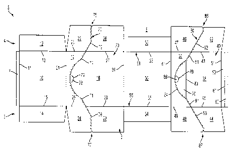
[00151 FIG. 1 is a plan view of a carton blank.
[00161 FIG. 2 shows a perspective view of a front portion of a carton formed
from the blank of FIG. 1.
[00171 FIG. 3 shows a perspective view of a back portion of the carton of FIG.
2.
100181 FIG. 4 shows a perspective view of the lower portion of the carton of
FIG. 2 with the dispenser
portion removed.
100191 FIG. 5 is a perspective view of the lower portion of the carton of FIG.
4 with the accordion
panels engaged to lower the back wall of the carton.
[00201 FIG. 6 shows a side view of the lower portion of the carton with
product disposed therein.
[00211 FIG. 7 shows a side view of the lower portion of the carton with the
accordion feature engaged
and with the product slanted toward the rear of the lower portion of the
carton.
[00221 Corresponding parts are designated by corresponding reference figures
throughout the drawings.
Detailed Description of the Exemplary Embodiments
[00231 This disclosure generally relates to cartons suitable for storing and
dispensing contents or
articles, methods of erecting such cartons from a carton blank, methods of
dispensing from the
formed carton, and a carton for and methods for slanting or tilting product
within the carton
toward a rear portion of the carton. For purposes of illustration and not
limitation, the detailed
description below describes several embodiments of the invention within the
context of a carton
with an opener for dispensing contents or articles from the carton. Further,
references herein to
"end," "side," "front," "rear," "bottom," and "top" refer to orientations and
positions of elements
when the carton is erected and/or disposed in an upright orientation. The
terms "upper,"
"lower," "vertical," "horizontal," and "oblique," and any variations thereof,
generally refer to the
location and/or orientation of an element or line with respect to a drawing
figure in which it
6
CA 02704443 2010-05-14
appears. Reference characters shared among the various embodiments disclosed
herein include
similar parts.
[0024] FIG. 1 illustrates an outer facing surface 1 of a carton blank 5 from
which a carton 100 (FIGS.
2-5) can be erected. The blank 5 (FIG. 1) includes a first side 4, a second
side 6, an adhesive
panel 7, a first panel 10, a second panel 20, a third panel 30, a fourth panel
40, a fifth panel 50,
and a sixth panel 60. Panel 20 is separated into first panel portion 18 and
second panel portion
19. Panel 40 is separated into third panel portion 38, fourth panel portion
39, and panel flap 90.
Adhesive flap 7 is foldably connected along fold line 11 to panel 10, panel 10
is foldably
connected along fold line 21 to second panel portion 19, first panel portion
18 is foldably
connected along fold line 31 to panel 30, panel 30 is foldably connected along
fold line 41 to
fourth panel portion 39, third panel portion 38 is foldably connected along
fold line 51 to panel
50, and panel 50 is foldably connected along fold line 61 to panel 60. First
panel portion 18 and
second panel portion 19 are separated by tear line segments 71 and 74 of tear
line 70. Panel flap
90 is disposed between third panel portion 38 and fourth panel portion 39,
with panel flap 90
being connected along fold line 83 to third panel portion 38 and with panel
flap 90 separated
along tear line segment 84 from fourth panel portion 39. Third panel portion
38 is separated
from fourth panel portion 39 along tear line segments 81 and 91.
[0025] As indicated in FIG. 1, blank 5 includes end flaps 12, 22, 26, 32, 42
and 46 disposed along the
first side 4 and end flaps 14, 24, 28, 34, 44 and 48 disposed along the second
side 6 of the blank.
End flap 12 is connected along a fold line 13 at the first end 4 of panel 10.
End flap 14 is
foldably connected along a fold line 15 at the second end 6 of panel 10. End
flap 22 is foldably
connected along a fold line 23 to the second panel portion 19. End flap 26 is
foldably connected
to the first panel portion 18 along fold line 27. End flap 22 and end flap 26
are separated along
7
CA 02704443 2010-05-14
tear line segment 72 of tear line 70. End flap 24 is foldably connected along
a fold line 25 to the
second panel portion 19, while end flap 28 is foldably connected along a fold
line 29 to the first
panel portion 18. End flap 24 and end flap 28 are separated along tear line
segment 76 of tear
line 70. End flap 32 is foldably connected along a fold line 33 to the panel
30, while end flap 32
is foldably connected along fold line 35 to panel 30.
[0026] End flap 46 is foldably connected along fold line 47 to fourth panel
portion 39, and end flap 42 is
foldably connected along fold line 43 to third panel portion 38. The end flaps
42 and 46 are
separated along tear line segment 82 of tear line 80. End flap 48 is foldably
connected along a
fold line 49 to the fourth panel portion 39, and end flap 44 is foldably
connected along fold line
45 to the third panel portion 38. End flap 44 and end flap 48 are separated
along tear line
segment 86 of tear line 80. As shown in FIG. 1, the end flaps 12, 14, 22, 24,
42, 44 typically can
include angled configurations that will enable the accordion panels 50 and 60
to lower the third
panel portion 38 toward the panel 30 when the blank 5 is configured in a
carton configuration
(FIGS. 2-5).
[0027] As FIG. 1 indicates, fold lines 13, 15, 23, 25, 27, 29, 33, 35, 43, 45,
47, and 49 are generally
transverse to fold lines 11, 21, 31, 41, 51, and 61. One or more of fold lines
13, 23, 27, 33, 43,
47 could be replaced by a single fold line, such as indicated at 53, and one
or more of fold lines
15, 25, 29, 35, 45, and 49 could be replaced by a single fold line, such as
indicated at 55. End
flaps 12, 14, 22, 24, 26, 28, 32, 34, 42, 44, 46, and 48 generally extend in a
direction away from
respective fold lines 13, 15, 23, 25, 27, 29, 33, 35, 43, 45, 47, and 49
toward periphery 8 of blank
5. Further, in view of "panels," the surfaces of carton 100 (FIG. 2) formed
from the blank 5 can
be referred to as "walls" or "sides." Further still, the panels 10, 20, 30, 40
can be referred to as
the surfaces they forms when constructed in the form of a carton, such as the
carton shown in
8
CA 02704443 2010-05-14
FIGS. 2-5. For example, panel 10 can be referenced as bottom panel, panel 20
can be referenced
as first side panel, panel 30 can be referenced as top panel, and panel 40 can
be referenced as
second side panel. Additionally, end flaps 12, 22, 26, 32, 42, 46 can be
closed to form a first
carton end, and end flaps 14, 24, 28, 34, 44, 48 can be closed to form a
second carton end.
[0028] As indicated above, tear lines 70 and 80 can be separated into tear
line segments. Tear line 70
can include segments 71, 72, 74, and 76, which also can be formed as a
continuous tear, line or
less than all segments can extend as continuous. As shown in FIG. 1, tear line
segments 71 and
74 are separated by an opening, finger flap, or finger hole 78, which is
defined along its
periphery by cut or fold line 79. Tear line 70 extends to a notch 75 at the
periphery 8 of end
flaps 22 and 26 at the first end 4. Tear line 70 extends to a notch 77 at the
periphery 8 of end
flaps 24 and 28 at the second end 6. Tear line 80 is shown in FIG. I with tear
line segments 81,
82, 84, 86, and 91. Tear line segment 84 is separated into two portions by an
opening, finger
flap, or finger hole 88, which is defined along its periphery by cut or fold
line 89. Tear line 80
extends to a notch 85 at the periphery 8 of end flaps 42 and 46 at the first
end 4. Tear line 80
extends to a notch 87 at the periphery 8 of end flaps 44 and 48 at the second
end 6. Notches 75,
77, 85, and 87 are included for various reasons, such as to assist in the
separation of the
dispensing portion 95 (FIGS. 2 and 3) of the carton 100 along tear line
segments 70 and 80.
100291 FIG. 2 shows a front view of a carton formed from the blank of FIG. 1.
The blank 5 may be
folded from the configuration shown in FIG. 1 to the configuration shown in
FIGS. 2 and 3 by
folding the blank along fold lines 11, 21, 31, 41, and 51 such that the panels
10 and 30 extend
substantially parallel to each other, and that the panels 20 and 40 extend
substantially parallel to
each other between the first panel 10 and the second panel 30 to form the
carton 100. During a
folding sequence, the end flaps are folded toward an interior area of the
carton, with either the
9
CA 02704443 2010-05-14
end flaps along the first side 4 or the end flaps along the second side 6
folded inward first. At
end 4, end flap 12 and end flap 32 are folded inwardly along fold lines 13 and
33, respectively,
so as to extend substantially perpendicular to panels 10 and 30. End flaps 22
and 26 and end
flaps 42 and 46 are folded along fold lines 23, 27, and 43, 47, respectively,
so as to extend
substantially perpendicular to panels 20 and 40. End flaps 22 and 42 and end
flaps 46 and 26
will generally partially overlap and, as shown in FIGS. 2-5, generally, end
flaps 22 and 26 will
overlap over end flaps 42 and 46 along the first carton side 4. Along the
second side 6, end flap
14 and end flap 34 are folded along fold lines 15 and 35, respectively, so as
to extend
substantially perpendicular to panels 10 and 30. End flaps 24, 28 and end
flaps 44 and 48 are
folded along fold lines 25, 29, and 45, 49, respectively, so as to extend
substantially
perpendicular to panels 20 and 40. End flaps 24 and 28 and end flaps 44 and 48
will generally
partially overlap and, as shown in FIGS. 2-5, end flaps 24 and 28 generally
will overlap over end
flaps 44 and 48 along the second carton side. When folded to form the carton
100, tear lines 70
and 80 are disposed in an essentially continuous alignment to define an upper
carton half 95 and
a lower carton half 93, with the upper carton half 95 comprising a dispensing
portion. As shown
in FIG. 2, the opening or finger flap 78 disposed at a lower portion of the
carton 100.
[0030] FIG. 3 shows the back view of the carton of FIG. 2, with the opening or
finger flap 88 disposed
at an upper portion of carton 100.
[0031] FIG. 4 shows the lower portion of the carton with the dispensing
portion 95 removed from the
carton. Generally, the dispensing portion 95 is removed by a user inserting
their finger or
another object into opening or finger flap 78 or 88 to detach the dispensing
portion 95 from the
lower portion 93 along tear line 78 and tear line 80. Once the dispensing
portion 95 is removed
from the lower portion 93, product P (FIGS. 6 and 7) can be removed from the
carton 100. As
CA 02704443 2010-05-14
shown in FIG. 4, panels 50 and 60 are disposed generally parallel to panel 40.
When formed into
a carton, adhesive flap 7 generally is attached to panel 60, such as by an
adhesive such as glue.
[0032] FIG. 5 shows the lower portion of the carton with the accordion feature
engaged. When desired,
as shown in FIGS. 4-5, the panel 40, here acting as a back panel, is
compressed downwardly
with panels 50 and 60 collapsing or folding along fold lines 51 and 61 in an
accordion manner to
dispose these panels in an orientation non-parallel to panel 40. Specifically,
as shown in FIG. 5,
panel 60 is folded downwardly so as to be parallel to bottom panel 10 and
panel 50 is moved
outwardly to be disposed in a slanted or diagonal orientation, extending
between the connection
to panel 60 (along fold line 61) to the connection with third panel portion 38
(along fold line 51).
In this manner, panels 50 and 60 accordion, compress, or otherwise collapse
into an orientation
that lowers panel 40 toward bottom panel 10. By lowering panel 40 toward
bottom panel 10,
articles or product in lower portion 93 are slanted rearward, or otherwise
disposed in an
orientation that influences slanting or leaning of product toward the rear of
the lower portion 93
as indicated in FIG. 7. This orientation also mitigates tendency of the
product from falling
forward, i.e. away from third panel portion 38. The present accordion feature
thus provides a
carton that enables, for example, product disposed on a retailer's shelf to be
oriented to slant the
product in a rearward direction to allow, for example, ease of viewing of
product disposed in
lower portion 93 and to keep product from falling out of lower portion 93
(which can occur if the
product slanted forward instead of rearward).
[0033] FIG. 6 shows the front view of the lower portion of the carton with
product disposed therein.
The back panel is at a first position 200. FIG. 7 shows the front view of the
lower portion of the
carton with the accordion feature engaged and with the product slanted toward
the rear of the
11
CA 02704443 2010-05-14
lower portion of the carton. The back panel has moved from the first position
200 to a second
position 300.
[0034[ Generally, the carton is filled with items, such as pizzas, etc. for
example, to form a package.
The carton can be sized to accommodate any number of items. Generally, the
items are
contained in the package for shipping to a point-of-sale vendor (e.g., grocery
store). Optionally,
at the point-of-sale vendor, the package can be converted to a display unit
for displaying the
items to consumers.
[00351 The flaps and panels detailed herein generally are secured to form a
package, or carton. It is
understood that forming the carton, packing the carton, and/or loading the
carton and methods
that differ than the forming, packing, and/or loading configurations discussed
herein are within
the scope of the disclosure.
[00361 In general, the blank may be constructed from paperboard having a
caliper of at least about 13,
for example, so that it is heavier and more rigid than ordinary paper. The
blank can also be
constructed of other materials, such as cardboard, or any other material
having properties
suitable for enabling the carton to function at least generally as described
above.
[00371 The blank can be coated with, for example, a clay coating. The clay
coating may then be printed
over with product, advertising, and other information or images. The blanks
further may be
coated with a varnish to protect information printed on the blanks. The blanks
may also be
coated with, for example, a moisture barrier layer, on either or both sides of
the blanks. The
blanks can also be laminated to or coated with one or more sheet-like
materials at selected panels
or panel sections.
[00381 The above embodiments may be described as having one or panels adhered
together by glue.
The term "glue" is intended to encompass all manner of adhesives commonly used
to secure
12
CA 02704443 2010-05-14
paperboard or carton panels in place, and the adhesive material can be
replaced by, or
supplemented with any suitable fastening devices.
100391 The term "line" as used herein includes not only straight lines, but
also other types of lines such
as curved, curvilinear or angularly displaced lines. In accordance with the
exemplary
embodiments, a fold line can be any substantially linear, although not
necessarily straight, form
of weakening that facilitates folding therealong. More specifically, but not
for the purpose of
narrowing the scope of the present disclosure, fold lines include: a score
line, such as lines
formed with a blunt scoring knife, or the like, which creates a crushed or
depressed portion in the
material along the desired line of weakness; a cut that extends partially into
a material along the
desired line of weakness, and/or a series of cuts that extend partially into
and/or completely
through the material along the desired line of weakness; and various
combinations of these
features. In situations where cutting is used to create a fold line, typically
the cutting will not be
overly extensive in a manner that might cause a reasonable user to incorrectly
consider the fold
line to be a tear line.
[00401 As an example, a tear line can include: a slit that extends partially
into the material along the
desired line of weakness, and/or a series of spaced apart slits that extend
partially into and/or
completely through the material along the desired line of weakness, or various
combinations of
these features. As a more specific example, one type tear line is in the form
of a series of spaced
apart slits that extend completely through the material, with adjacent slits
being spaced apart
slightly so that a nick (e.g., a small somewhat bridging-like piece of the
material) is defined
between the adjacent slits for typically temporarily connecting the material
across the tear line.
The nicks are broken during tearing along the tear line. The nicks typically
are a relatively small
percentage of the tear line, and alternatively the nicks can be omitted from
or torn in a tear line
13
CA 02704443 2010-05-14
such that the tear line is a continuous cut line. That is, it is within the
scope of the present
disclosure for each of the tear lines to be replaced with a continuous slit,
cut line, or the like. For
example, a cut line can be a continuous slit or could be wider than a slit
without departing from
the present disclosure.
[00411 Any dimensions shown in the figures are exemplary only and can be
expanded or contracted,
such as to accommodate items of different sizes, configurations, or
dimensions. These
dimensions should not be construed as limiting in any manner.
[00421 The foregoing description of the disclosure illustrates and describes
various embodiments. As
various changes could be made in the above construction without departing from
the scope of the
disclosure, it is intended that all matter contained in the above description
or shown in the
accompanying drawings shall be interpreted as illustrative and not in a
limiting sense.
Furthermore, the scope of the present disclosure covers various modifications,
combinations,
alterations, etc., of the above-described embodiments that are within the
scope of the claims.
Additionally, the disclosure shows and describes only selected embodiments of
the disclosure,
but the disclosure is capable of use in various other combinations,
modifications, and
environments and is capable of changes or modifications within the scope of
the inventive
concept as expressed herein, commensurate with the above teachings, and/or
within the skill or
knowledge of the relevant art. Furthermore, certain features and
characteristics of each
embodiment may be selectively interchanged and applied to other illustrated
and non-illustrated
embodiments of the disclosure.
14