Note: Descriptions are shown in the official language in which they were submitted.
CA 02705028 2010-05-06
WO 2009/061294
PCT/US2007/023374
TUBULAR ELECTROCHEMICAL CELL
INTRODUCTION
100011 Electrochemical devices, such as fuel cells, oxygen pumps, sensors and
the
like, generally offer opportunities for an efficient conversion of chemical
energy to
electrical power with minimal pollution. Electrochemical devices generally
comprise an electrochemical cell, which is available in planar, tubular, or
monolithic
designs. The various designs suffer from several drawbacks, e.g., slow start-
up for
planar solid oxide fuel cells ("SOFCs") and lower volumetric power density for
tubular SOFCs.
[0002] Although tubular cell designs have demonstrated adequate thermal shock
resistance and high mechanical strength, they can have low volumetric power
packing density relative to other cell designs. For example, in order to
generate an
equivalent amount of power, a tubular electrochemical cell is generally much
larger
in size than a planar or monolithic electrochemical cell. One of the drawbacks
of
increasing the size of an electrochemical cell (i.e., the diameter or the
length) to
generate larger amounts of power is lower volumetric power density. However,
reducing the size of the tubular cell can increase the volumetric power
density of an
electrochemical cell stack containing many tubular cells. Unfortunately, too
many
cells in a stack can complicate operation and increase manufacturing costs.
100031 There is, therefore, a need for improving the power and voltage
performance
of tubular electrochemical cell.
SUMMARY
[00041 In satisfaction of this need and others, the present teachings relate
to an
electrochemical cell comprising an anode layer, a cathode layer, an
electrolyte layer
in ionic or protonic communication with one of the anode layer and the cathode
layer, a fuel channel bounded by the anode layer, and oxidant channel bounded
by
the cathode layer, wherein the anode layer, the electrolyte layer, and the
cathode
layer together substantially form a closed Fermat spiral.
CA 02705028 2010-05-06
WO 2009/061294
PCT/US2007/023374
[0005] Another embodiment of the present teachings relates to an
electrochemical
cell comprising an electrolyte layer interposed between an anode layer and a
cathode
layer to form a multilayer member, where the multilayer member substantially
can
form a closed Fermat spiral comprising a fuel channel and an oxidant channel.
The
anode layer, the cathode layer, and the electrolyte layer each can have a
substantially
planar dimension and the anode layer and the cathode layer can be in at least
one of
ionic and protonic communication with the electrolyte. The fuel channel can
comprise an inner boundary formed by the anode layer and an outer boundary
formed by the anode layer. The oxidant channel can comprise an inner boundary
formed by the cathode layer and an outer boundary formed by the cathode layer.
[0006] In some embodiments, the anode layer also can have a reforming layer.
The
anode layer, the electrolyte layer, and the cathode layer each can have a
width
between about 5 pm and about 2 mm. The electrochemical cell can be an anode-
supported electrochemical cell, a cathode-supported electrochemical cell, an
electrolyte-supported electrochemical cell, a metal-supported electrochemical
cell,
or a substrate-supported electrochemical cell. The fuel channel and the
oxidant
channel each can have a width between about 0.1 mm and about 5 mm. The
electrolyte layer can comprise an ionic conductor or a protonic conductor. In
certain
embodiments, the electrochemical cell can be a solid oxide fuel cell.
[0007] Another aspect of the present teachings relates to a method of making
an
electrochemical cell. The method can include forming a first layer
substantially into
a closed Fermat spiral wherein the first layer can have a first side and a
second side,
associating a second layer with at least a portion of the first side of the
first layer,
and associating a third layer with at least a portion of the second layer. In
some
embodiments, the first layer can be pre-fired. In some embodiments, the first
layer
and the second layer can be fired. In some embodiments, the entire
electrochemical
cell can be fired. The first layer can be formed by extruding, gel-casting, 3-
D
printing, or rolling a pre-form tape. The second layer can be associated with
the first
layer by dip coating or gel-casting. The third layer can be associated with
the
second layer by dip-coating or gel-casting. The second side of the first layer
can be
masked to facilitate the application of the second layer and the third layer.
In some
embodiments, the first layer and the third layer each can comprise an
electrode
-2-
CA 02705028 2010-05-06
WO 2009/061294
PCT/US2007/023374
material and the second layer can comprise an electrolyte material. In some
embodiments, a reforming catalyst can be associated with the second side of
the first
layer or the exposed side of the third layer. In some embodiments a fourth
layer can
be associated with the third layer, where the first layer is a support, the
second and
fourth layers are electrode and the third layer is an electrolyte.
10008] In certain embodiments, a method of making an electrochemical cell
comprises forming an electrolyte layer substantially into a closed Fermat
spiral
wherein the electrolyte layer can have a first side and a second side,
associating a
cathode layer with at least a portion of the first side of the electrolyte
layer, and
associating an anode layer with at least a portion of the second side of the
electrolyte
layer.
10009] Another aspect of the present teachings relates to a method of
operating an
electrochemical cell. In some embodiments, a method of operating a
substantially
cylindrical electrochemical cell comprises causing a fuel to flow through the
electrochemical cell, wherein the fuel enters the electrochemical cell at a
first
average fuel radius and exits at a second average fuel radius and causing an
oxidant
to flow through the electrochemical cell, wherein the oxidant enters the
electrochemical cell at a first average oxidant radius and exits at a second
average
oxidant radius. In some embodiments, the fuel and the oxidant flow can flow in
the
same axial direction. In certain embodiments, the fuel and the oxidant can
flow in
opposite axial directions. In some embodiments, the first average fuel radius
is
smaller than the second average fuel radius and the first average oxidant
radius is
smaller than the second average oxidant radius.
100101 In various embodiments, a method of operating an electrochemical cell
comprises directing a fluid through an electrochemical cell, wherein the
electrochemical cell is substantially cylindrical and has an axial length, and
wherein
the fluid has a concentration, and varying the concentration of the fluid
radially
along at least part of the axial length of the electrochemical cell.
[0011] In certain embodiments, a method of operating a substantially
cylindrical
electrochemical cell comprises directing a fuel stream into the
electrochemical cell
approximately along an axis of the electrochemical cell, and exposing the fuel
-3-
CA 02705028 2010-05-06
WO 2009/061294
PCT/1JS2007/023374
stream within the electrochemical cell to an increasing anode surface area
along at
least a portion of the axial length of the electrochemical cell.
BRIEF DESCRIPTION OF THE DRAWINGS
[0012] It should be understood that the drawings are not necessarily to scale,
with
emphasis generally being placed upon illustrating the principles of the
present
teachings. The drawings are not intended to limit the scope of the present
teachings
in any way.
[0013] FIG. 1 is a schematic of a Fermat spiral.
[0014] FIG. 2 is a schematic of a closed Fermat spiral.
[0015] FIG. 3 is schematic perspective view of an embodiment of an
electrochemical cell according to the present teachings.
[0016] FIG. 4 is a cross-sectional view at 3A-3B of the embodiment illustrated
in
FIG. 3.
[0017] FIG. 5 is a high-level flow chart of an embodiment of a method of
manufacturing the electrochemical cell of the present teachings.
[0018] FIG. 6 is a high-level flow chart of an embodiment of a method of
operating
the electrochemical cell of the present teachings.
DETAILED DESCRIPTION OF THE PRESENT TEACHINGS
10019] The present teachings can provide an electrochemical cell with improved
power and voltage performance, as well as fuel utilization, without an
increase in the
outer dimensions of the electrochemical cell. For example, the present
teachings
. .
include a tubular electrochemical cell having an internal structure
representative of a
Fermat spiral. In an embodiment, the internal structure is a substantially
planar
multilayer member¨comprising an anode, cathode and electrolyte¨representative
of a closed Fermat spiral shape so that a fuel channel and an oxidant channel
are
formed on either side of the multilayer member. The present teachings can be
used
to design an electrochemical cell with a higher volumetric power density as
compared to a prior art tubular electrochemical cell of the same outer
dimensions.
-4-
CA 02 7 0502 8 2 0 14-0 3-25
CA 2,705,028
Blakes Ref: 70578/00005
[0020] Throughout the description, where devices or compositions are
described as
having, including, or comprising specific components, or where processes are
described as
having, including, or comprising specific process steps, it is contemplated
that compositions of
the present teachings also consist essentially of, or consist of, the recited
components, and that
the processes of the present teachings also consist essentially of, or consist
of, the recited
processing steps. It should be understood that the order of steps or order for
performing certain
actions is immaterial so long as the method remains operable. Moreover, two or
more steps or
actions can be conducted simultaneously.
[0021] In the application, where an element or component is said to be
included in
and/or selected from a list of recited elements or components, it should be
understood that the
element or component can be any one of the recited elements or components and
can be
selected from two or more of the recited elements or components. Further, it
should be
understood that elements and/or features of a composition, an apparatus, or a
method
described herein can be combined in a variety of ways without departing from
the scope of the
appended claims.
[0022] It is to be understood that the figures and descriptions of the
present invention
have been simplified to illustrate elements that are relevant for a clear
understanding of the
present teachings while eliminating, for purposes of clarity, other elements.
For example, certain
details relating to extrusion, gel-casting, or 3-D printing are not described
herein. Those of
ordinary skill in the art will recognize, however, that these and other
manufacturing techniques
may be useful to create complex shapes. A detailed discussion of such
techniques is not
provided because such techniques are well known in the art and because they do
not facilitate a
better understanding of the present teachings.
[0023] The use of the terms "include," "includes," "including," "have,"
"has," or "having"
should be generally understood as open-ended and non-limiting unless
specifically stated
otherwise.
22528217.1
CA 02705028 2010-05-06
WO 2009/061294
PCT/US2007/023374
[0024] The use of the singular herein includes the plural (and vice versa)
unless
specifically stated otherwise. In addition, where the use of the term "about"
is
before a quantitative value, the present teachings also include the specific
quantitative value itself, unless specifically stated otherwise.
[0025] In the following discussion of illustrative embodiments, the term
"Fermat
spiral" generally refers to a parabolic spiral, such as a spiral 50 shown in
FIG. 1.
The spiral 50 is a Fermat spiral, a type of Archimedean spiral, that follows
the
equation
r = 01/2
in polar coordinates (the more general Fermat's spiral follows r2 = a20).
Those
skilled in the art will appreciate that variations of the Fermat spiral may be
used
without departing from the principles of the present teachings.
[0026] The term "closed Fermat spiral" refers to a Fermat spiral in which the
spiral
closes upon itself, such as in the manner shown in FIG. 2. FIG. 2 shows an
exemplary closed Fermat spiral 2 in which a first end 4 and a second end 6 are
closed.
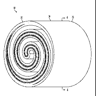
[0027] FIG. 3 is schematic perspective view of an exemplary electrochemical
cell
10 having a generally cylindrical shape and a cross section representative of
a closed
Fermat spiral according to the present teachings. As shown, the
electrochemical cell
10 includes a first end 32, a midpoint 34, and a second end 36.
[0028] The electrochemical cell can be any type of electrochemical cell known
in
the art including, for example, a fuel cell or an electrolytic cell. The
present
teachings encompass fuel cells that operate at a wide range of temperatures,
including high temperature cells (e.g., solid oxide fuel cells and molten
carbonate
fuel cells) and low-temperature cells (e.g., phosphoric acid fuel cells and
proton
exchange membrane fuel cells).
[0029] FIG. 4 is a cross-sectional view at 3A-3B of the embodiment illustrated
in
FIG. 3. The electrochemical cell 10 can include an anode 12, an electrolyte
14, a
cathode 16, a fuel channel 18 (bounded by the anode 12), and an oxidant
channel 20
(bounded by the cathode 16). In the illustrated embodiment, the electrolyte 14
is
-6-
CA 02705028 2010-05-06
WO 2009/061294
PCT/US2007/023374
interposed between the anode 12 and the cathode 16 so that, together, the
anode 12,
= the electrolyte 14, and the cathode 16 form a multilayer member 19. The
multilayer
member 19, in turn, has a substantially cylindrical shape and exhibits a cross-
section
representative of a closed Fermat spiral. As shown, the electrochemical cell
10 also
includes a radial center 26, a half-radius 28, and a radius 30. In operation,
an
oxidant, such as air, flows through the oxidant channel 20 and fuel flows
through the
fuel channel 18 either in the same or an opposite axial direction. Oxidant
molecules
in the oxidant channel 20 permeate the cathode 16 and contact the electrolyte
14
where, in the case of an ionic conductor, oxygen ions are formed. The oxygen
ions
diffuse into the electrolyte 14 and migrate to the other side of the
multilayer member
19 where they encounter the anode 12 and fuel flowing through the fuel channel
18.
100301 The anode layer, (i.e., the anode) can have a substantially planar
dimension,
with a width ranging from about 5 gm to about 2,000 gm. The electrochemical
cell
can be anode-supported in that the anode is the load-bearing structure, e.g.,
has the
greatest mechanical strength among the anode, the cathode, and the
electrolyte. In
an anode-supported embodiment, the anode can have a width in the range of
about
0.5 mm to about 2 mm. According to such an embodiment, the electrolyte can
have
a width of about 5 gm to about 50 gm, and the cathode can have a width of
about 10
gm to about 100 gm.
100311 Compositionally, the anode can be made from any suitable porous
electrode
material known in the art. For example, the anode can be made from a ceramic
material or a cermet material. The ceramic material or the ceramic component
in the
cermet material can include, for example, a zirconia-based material or a ceria-
based
material. Exemplary materials include, but are not limited to, stabilized
zirconia
(e.g., yttria-stabilized zirconia, particularly (Zr02)o 92(Y203)0 08) and
doped ceria
(e.g., gadolinium-doped ceria, particularly (Ce0.90Gdo 10)01 95). In the case
of cermet
materials, the metallic component can include one or more transition metals,
their
alloys, and/or physical mixtures. The metallic component (e.g., Ni, Co, Cu,
Ag, and
W) can be introduced in the form of an oxide or a salt (e.g., NiO, Ni(NO3)2),
and can
be present in a range from about 30.0 vol. % to about 80.0 vol. % based on the
total
volume of the cermet material. For example, the anode can be a porous nickel
cermet with yttria-stabilized zirconia. Other suitable electrode materials
include
-7-
CA 02 7 0502 8 2 014-0 3-25
CA 2,705,028
Blakes Ref: 70578/00005
alumina and/or titanium oxide based ceramics that may or may not include a
metallic
component.
[0032] In various embodiments, the anode layer also can comprise a
reforming layer, as
disclosed in US Patent Number 8,435,683. The reforming layer can contain a
partial oxidation
reforming catalyst, a steam reforming catalyst and/or an autothermal reforming
catalyst. The
reforming layer and electrolyte layer can be associated with opposite sides of
the anode layer,
either in whole or in part. Those skilled in the art will appreciate that the
reforming layer can be
associated with the anode layer of the electrochemical cell, whether the cell
is anode-supported,
cathode-supported, electrolyte-supported or substrate-supported.
[0033] The cathode layer (i.e., cathode) can have a substantially planar
dimension, with
a width ranging from about 5 pm to about 2 mm. The electrochemical cell can be
cathode-
supported. For a cathode-supported electrochemical cell, the cathode can have
a width in the
range of about 0.5 mm to about 2 mm. In a cathode-supported electrochemical
cell, the
electrolyte can have a width of about 5 pm to about 50 pm, and the anode can
have a width of
about 5 pm to about 100 pm. The cathode can be any electrically conductive,
porous material
known in the art. Examples of suitable cathode materials include various
perovskites such as,
but not limited to, lanthanum manganite perovskite ceramics, lanthanum ferrite
perovskite
ceramics, praseodymium manganite perovskite ceramics, and praseodynium ferrite
perovskite
ceramics.
[0034] The electrolyte layer (i.e., electrolyte) can have a substantially
planar dimension,
with a width ranging from about 5 pm to about 2,000 pm. The electrochemical
cell can be
electrolyte-supported. For an electrolyte-supported electrochemical cell, the
electrolyte can have
a width in the range of about 0.1 mm to about 2 mm. In the electrolyte-
supported
electrochemical cell, the anode can have a width of about 5 pm to about 100
pm, and the
cathode can have a width of about 5 pm to about 100 pm.
8
22528217.1
CA 02705028 2010-05-06
WO 2009/061294
PCT/US2007/023374
[0035] The electrolyte layer (i.e., electrolyte) can be any ionically or
protonically
conductive material. In some embodiments, the electrolyte can be made from
ceramic or cermet materials.
[0036] An ionic conductor permits the transfer of ions through the electrolyte
layer.
Ionic conductors are solid state electrical conductors that are conductive
because of
the movement of ions through void spaces in the conductor's crystal lattice.
Suitable ionic conductor materials include fluorite-structured electrolytes,
zirconia-
based oxide ion conductors, ceria-based oxide ion conductors, perovskite-
structured
electrolytes, and Brownmillerites.
[0037] A protonic conductor permits the transfer of protons through the
electrolyte
layer. A protonic conductor is an electrolyte, such as a solid electrolyte, in
which
movable hydrogen ions (protons) are the primary charge carriers. Proton
conductors
may be composed of a polymer or a ceramic. Suitable protonic conductor
materials
include BaCe03-based compounds; SrZr03 based compounds; CaZr03 based
compounds; BaTh03 and BaTb03 doped with Gd; BaTh0.9Ga0.103, Sr2Gd205; and
Sr2Dy205. In various embodiments, the electrolyte layer can be made from a
doped
ceramic, such as a thin and dense layer of doped zirconia.
[0038] The fuel channel permits the delivery of fuel to the anode. The fuel
channel
can have a width between about 0.1 mm to about 5 mm, defined by the spacing
between the anode layers, as shown in FIG. 4. In this way, the fuel channel
has an
inner boundary formed by the anode layer and an outer boundary formed by the
anode layer. Those skilled in the art will appreciate that the fuel channel
can be
configured to receive fuel at either end of the electrochemical cell.
[0039] The oxidant channel permits the delivery of oxidant to the cathode. The
oxidant channel can have a width between about 0.1 mm to about 5 mm, defined
by
the spacing between the cathode layers, as shown in FIG. 4. In this way, the
oxidant
layer has an inner boundary formed by the cathode layer and an outer boundary
formed by the cathode layer. Those skilled in the art will appreciate that the
oxidant
channel can be configured to receive oxidant at either end of the
electrochemical
cell.
-9-
CA 02705028 2010-05-06
WO 2009/061294
PCT/US2007/023374
100401 The electrochemical cell can also include a support layer, in addition
to the
anode, cathode, and electrolyte, for mechanical support of the cell. Exemplary
support materials can include cermets, ceramics, for example, alumina,
zirconia, and
lathanium chromite; and metals.
100411 FIG. 5 depicts a flow diagram of an exemplary method 500 of
manufacturing
an electrochemical cell according to the present teachings. In step 502, a
support
structure or first layer is formed in the shape of a Fermat spiral using
techniques
known to those skilled in the art, including extrusion, gel-casting, or 3-0
printing.
Step 502 also can include firing the first layer at the appropriate
temperature to
create a solid support.
100421 Extrusion is a manufacturing process used to create objects of a fixed
cross-
sectional profile. The first layer can be pushed and/or drawn through a die of
the
desired profile shape, i.e., a closed Fermat spiral.
100431 Gel-casting is a forming process similar to slip casting for making
complex
shapes. In gel-casting, a slip of ceramic powders is combined with a solution
of
organic monomers and introduced into a mold. The contents of the mold can be
polymerized to form a strong, cross-linked structure. The mold can be made
from
various materials including metals and organic materials (i.e., wax, polymer,
and
graphite.). With an organic mold, demolding is not necessary, as the organic
mold
can be burned off during the heat treatment. In accordance with the present
teachings, the mold can be in the shape of a Fermat spiral.
100441 Three dimensional printing (3-D printing) refers to building of a
desired
shape in layers. Using a computer model of the shape or desired part, a
slicing
algorithm generates detailed information for each layer. Each layer begins
with a
thin distribution of powder spread over the surface of a powder bed. Using a
technology similar to ink-jet printing, a binder material selectively joins
the powder
particles where the layer is to be formed. A piston, which supports the powder
bed
and the part-in-progress, lowers so that the next powder layer can be spread
and
selectively joined. This layer-by-layer process repeats until the part is
completed.
After removing the unbound powder, a heat treatment may be necessary to burn
the
-10-
CA 02705028 2010-05-06
WO 2009/061294
PCT/US2007/023374
binder, increase the part strength, and/or create desirable structure for the
next
processing step.
[0045] In step 504, after. the first layer has been formed and, in some
embodiments,
fired, a second layer can be associated with at least a portion of a first
side (i.e., the
opposite side to which the reforming layer was applied) of the first layer or
the entire
first layer. The second layer can be associated with the first layer through
dip
coating, gel-casting, or other thin film application means.
[0046] Dip coating comprises preparing a solution of the second layer
materials and
dipping the first layer into the solution, coating the anode with the second
layer.
Certain areas of the first layer can be masked to limit coating to certain
areas. The
mask can be tape, wax, or any other material or method known to one of skill
in the
art that protects the masked areas from exposure to the solution. For example,
if the
first layer is to be coated with the second layer on the first side of the
first layer, the
second side of the first layer can be masked so that solution will expose only
the first
side of the first layer. After the second layer has been associated with the
first side
of the first layer, the masking can be removed and both the second layer and
the first
layer can be fired.
[0047] In step 506, a third layer can be associated with the second layer. The
third
layer can be associated with at least a portion of the second layer or the
entire
second layer. The third layer can be associated with the second layer in the
same
manner as was described above for associating the second layer with the first
layer:
dip coating, gel-casting, or other thin film application means. After the
third layer
has been associated with the second layer, the entire electrochemical cell can
be
fired.
[0048] If the first layer is a substantially planar anode layer having a first
side and a
second side, a reforming layer can be applied to the second side of the anode
in the
same manner as described above for associating the second layer with the first
layer.
[0049] In various embodiments, the first and third layers can be an electrode
and the
second layer can be an electrolyte. In some embodiments, the first layer can
be an
anode, the third layer can be a cathode, and the second layer can be an
electrolyte,
creating an anode-supported electrochemical cell. In some embodiments, the
first
-11-
.
CA 02705028 2010-05-06
WO 2009/061294
PCT/US2007/023374
layer can be a cathode, and the third layer can be an anode, and the second
layer can
be an electrolyte, creating a cathode-supported electrochemical cell. In the
cathode-
supported electrochemical cell, a reforming layer can be associated with the
third
layer, i.e., the anode layer as discussed above.
100501 In some embodiments, the first layer is an electrolyte and the second
and
third layers are electrodes, both associated with the first layer, creating an
electrolyte-supported electrochemical cell. The second layer and the third
layer can
be associated with the first layer using dip coating, gel-casting, or other
thin film
application means, as described above. If the third layer is the anode layer,
a fourth
reforming layer can be associated with the anode.
[00511 In various embodiments, the electrochemical cell can be substrate-
supported,
comprising a fourth layer associated with at least a portion of the third
layer. In
these embodiments, the first layer can be a substrate, the second and fourth
layers
can be electrodes and the third layer can be an electrolyte, creating a
substrate-
supported electrochemical cell. The substrate may be composed of ceramics,
cermets, or metals. Additionally, a fifth layer can be associated with fourth
layer,
e.g., the fifth layer can be a reforming layer associated with an anode layer.
Additionally, whole or partial reforming materials can be implemented in the
support layer. Whole reforming implies that an incoming fuel can be completely
reformed at the reforming layer located in the support layer. Partial
reforming
implies that the reforming layer located in the support layer only can reform
part of
the incoming fuel. The remainder of the incoming fuel could be, in some
embodiments, reformed on the anode of the fuel cell.
[0052] In some embodiments, the fuel channel and the oxidant channel can be
formed using the extrusion, gel-casting, or 3-D printing processes discussed
above.
In some embodiments, the channels can be made using pore formers. Pore formers
are materials that can be destructively removed to create void channels in an
object.
Exemplary pore formers include but are not limited to: carbon-based materials,
straws or textiles, including woven, knitted, knotted, tufted, tied or unwoven
fiber,
or fabric materials. The carbon, graphite, or other materials can be
destructively
removed through combustion, by dissolution with a solvent, or any other means
-12-
CA 02705028 2010-05-06
WO 2009/061294
PCT/US2007/023374
known to one in skill in the art for removing a pore former from a ceramic or
cermet
without damaging the ceramic or cermet structure.
[0053] Another aspect of the present teachings relates to a method of
operating an
electrochemical cell. The method comprises causing a fuel to enter the fuel
channel
of the electrochemical cell and directing an oxidant into the oxidant channel
of the
electrochemical cell. The fuel can be hydrogen (when the anode does not have a
reforming layer) or the fuel can be hydrocarbon mixtures that are reformed on
the
anode reforming layer. Depending on the type of reformer applied to the anode
layer, the hydrocarbon mixture may be any form of gaseous or liquid
hydrocarbons
and the hydrocarbons that can be mixed with air (partial oxidation reforming)
or
steam (steam or autothermal reforming).
10054] FIG. 6 is a high level flow chart of an exemplary method 600 of
operating
the electrochemical cell of the present teachings. Referring to both FIG. 4
and FIG.
6, the method 600 begins in step 602 as fuel enters the electrochemical cell
at, for
example, the first end 32. The fuel can be directed into the fuel channel 18
somewhat uniformly along the entire cross-section of the electrochemical cell.
In
another embodiment, the fuel can be directed into the fuel channel 18 at less
than the
entire cross-section of the electrochemical cell, such as solely in the
vicinity of the
radial center 26 of the electrochemical cell. In another example, the fuel can
be
directed into the electrochemical cell uniformly between the radial center 26
and the
half radius 28, or at some other point in the radial cross-section of the
electrochemical cell. Those skilled in the art will appreciate that directing
the fuel at
less than the entire cross-section of the cell can cause the fuel to diffuse
radially
outward as it passes longitudinally through the cell. For example, fuel
introduced
between the radial center 26 and the half radius 28 at the first end 32 can
diffuse
radially outward toward the radius 30 so that it exits the second end 36 at an
average
fuel radius greater than that at the first end 32. Those skilled in the art
will
appreciate that such radial diffusion can cause the concentration of fuel to
vary along
the length of the electrochemical cell. Although step 602 has been described
in
terms of fuel being introduced at the first end 32, those skilled in the art
will
appreciate that fuel can be introduced at the second end 36.
-13-
CA 02705028 2010-05-06
WO 2009/061294
PCT/US2007/023374
[0055] The fuel can be delivered to the electrochemical cell via any delivery
mechanism known to one of skill in the art. For example, the fuel can be
delivered
into the electrochemical cell via a fuel pump or using the pressure contained
within
the fuel container.
[0056] Step 604 of the method 600 includes causing an oxidant to flow through
an
electrochemical cell, wherein the oxidant enters at a first average oxidant
radius and
exits at a second average oxidant radius. The oxidant can be introduced into
the
electrochemical cell in substantially the same manner as described above in
reference to the fuel, but typically through the oxidant channel of the Fermat
spiral.
[0057] The fuel and the oxidant each can be directed at the same end of the
electrochemical cell or can be directed at opposite ends of the
electrochemical cell.
For example, the fuel can be directed into the fuel channel at the first end
of the
electrochemical cell and the oxidant can be directed into the oxidant channel
at the
second end.
[0058] In certain embodiments, the method of operating an electrochemical cell
comprises directing a fluid having a concentration through a substantially
cylindrical
electrochemical cell of the present teachings. Because of the structure of the
electrochemical cell, the concentration of the fluid varies radially along at
least part
of the axial length of the electrochemical cell. The fluid can be fuel,
oxidant, or
exhaust.
[0059] Referring to FIG. 4, those skilled in the art will appreciate that
biasing the
fuel stream (i.e., fuel) toward the radial center 26, as described above, can
expose
the fuel stream to an increasing anode surface area along at least a portion
of the
longitudinal axis of cell. For example, if the fuel stream is directed into
the radial
center of the Fermat spiral shaped electrochemical cell at the first end 32,
the fuel
stream may diffuse radially along the longitudinal axis of the cell and
encounter
more anode surface area with which to react. In that regard, those skilled in
the art
may also appreciate that directing a fuel stream at the radial center 26 may
flatten
the power profile of the cell.
-14-
CA 02705028 2010-05-06
WO 2009/061294
PCT/US2007/023374
[0060] Furthermore, the Fermat spiral design of the electrochemical cell can
modulate the temperature as compared to a standard tubular electrochemical
cell of
equal size. For example, if the fuel and oxidant are directed into the
electrochemical
cell at the radial center of the electrochemical cell, the highest
concentration of fuel
and oxidant will be at the radial center of the cell. The fuel and oxidant
will also be
moving at a higher velocity at the radial center of the electrochemical cell
than at the
radial edge of the cell. Some of the fuel and oxidant will not react at the
center of
the cell, despite the high concentrations, because of the relatively high
velocities of
the fuel and the oxidant. Therefore, the likelihood that the center of the
cell will
reach excessive temperatures decreases, thus, reducing the likelihood of
thermal
shock to the electrochemical cell. As the oxidant and fuel move radially
outward
along the spiral, their respective velocities decrease. This decrease in
velocity
increases the resident time that the fuel and the oxidant have to react with
the anode
and cathode. Additionally, as the fuel and oxidant disperse radially, each is
exposed
to more electrochemically active surface area with which to react. Thus, the
reaction
rate at the center of the cell is not significantly higher than at outer edge
of the cell.
Because the reaction rate is directly related to the operating temperature of
the
electrochemical cell, the radial temperature profile of the electrochemical
cell can be
somewhat flatter than in a standard tubular cell. Additionally, the spiral
shape of the
electrochemical cell can accommodate radial expansion of the cell when the
temperature of the cell increases during operation.
[0061] Embodiments of the present teachings also can significantly increase
cell and
stack volumetric power density relative to a standard tubular cell of similar
outer
dimensions. Because the fuel and the oxidant have an increased
electrochemically
active surface over which to react when compared with cells of similar outer
dimensions, a larger percentage of fuel will react, thus producing more
electricity
with the same outer dimensioned electrochemical cell. For example, depending
on
the design, the electrochemical cell of the present teachings can generate an
increased power output in the range of about a 50% to about a 300% power
increase
at the same operating conditions (i.e., fuel and oxidant flow rates,
temperatures,
electrical loading, and pressure.)
-15-
.
CA 0 2 7 050 2 8 2 0 14-0 3-25
CA 2,705,028
Blakes Ref: 70578/00005
Other Embodiments
[0062] The present teachings can be embodied in other specific forms, not
delineated
above, without departing from the scope of the appended claims. The foregoing
embodiments
are therefore to be considered in all respects illustrative rather than
limiting on the present
teachings described herein. Scope of the present invention is thus indicated
by the appended
claims rather than by the foregoing description, and all changes that come
within the meaning
and range of equivalency of the claims are intended to be embraced therein.
16
22528217.1